Dynamic Modeling and Composite Attitude Cooperative Control for Dumbbell-Shaped Spacecraft
Abstract
This study proposes a composite attitude coordination control approach to enhance attitude stability and suppress vibrations during the attitude maneuver of a dumbbell-shaped spacecraft (DSS). First, a dynamic model is formulated that accounts for actuator faults and external disturbances while enabling distributed attitude coordination control. Then, leveraging graph and consensus theories, an attitude coordination consistency algorithm is developed. A virtual leader is designed using model predictive control. Force synthesis techniques are integrated with attitude coordination methods featuring a virtual leader. A composite attitude coordination control strategy is developed in this way to ensure both attitude stability and vibration suppression. The system’s stability is analyzed using the Lyapunov theory. Finally, simulations demonstrate the effectiveness and practical feasibility of the proposed approach.
1. Introduction
The increasing complexity and diversity of space missions have led to spacecraft designs characterized by large-scale, flexible structures with intricate configurations. Modular spacecraft architectures are increasingly adopted to prevent payload interference, as exemplified by space stations [1], nuclear-powered spacecraft [2], high-precision payload spacecraft [3], and support systems for space telescopes. Among these, large space truss structures have become the preferred choice for support frameworks due to their lightweight construction and expansive span [4]. This has given rise to a distinct category of spacecraft with specialized configurations, known as DSS, which are particularly suited for such applications [5]. Existing studies indicate that attitude stabilization and vibration suppression during DSS attitude maneuvers remain critical challenges.
The unique configuration and mass distribution of DSS differ substantially from those of conventional spacecraft, resulting in distinct orbital–attitude dynamic characteristics. Unlike traditional rigid-body spacecraft with flexible attachments concentrated at the center, DSS consists of rigid capsules at both ends connected by a large, flexible space truss structure [6]. The modules at both ends exhibit substantial mass, while the system’s center of mass is located near the flexible structure. Given the high-frequency response, densely distributed modes, low damping, and low stiffness of large space truss structures [7], DSS exhibits strong nonlinear coupling and is susceptible to vibrations during on-orbit operations. These vibrations arise from attitude adjustments, thermal fluctuations, and external disturbances, compromising the accuracy and reliability of the support load. Traditional attitude control and vibration suppression methods prove inadequate in addressing these challenges, necessitating the development of advanced control strategies for DSS attitude stabilization and vibration mitigation.
Previous work [8] proposed an adaptive robust control (ARC) approach to achieve attitude maneuvering for DSS. Attitude control under uncertainties in the spacecraft’s rotational inertia was implemented using an ARC-based attitude controller, while steady-state performance was ensured with an ARC+CSPP controller. However, this method was developed for an idealized model and did not account for external disturbances or actuator failures.
In recent years, significant advancements have been made in attitude cooperative control (ACC) strategies. Most existing studies focus on multisatellite, multirobot, or multirobot arm coordination. A sliding mode-based collaborative attitude control method has been proposed for flexible satellite formations with unaligned actuator configurations [9]. A distributed control law has been developed to achieve attitude synchronization in multisatellite systems with parameter uncertainties [10]. Additionally, coupled attitude–orbit coordination control strategies have been investigated for satellite formations under uncertainty and actuator saturation constraints [11]. Several adaptive control methods have been introduced to enhance formation control capabilities, including actor–critic neural network–based control [12], finite-time ACC using adaptive neural networks [13], and learning-based adaptive attitude control [14]. Moreover, the distributed finite-time ACC problem for multirigid-body spacecraft has been explored. This exploration is in cases where only a subset of spacecraft can access reference attitude and angular velocity data [15]. A prediction-based adaptive sliding mode attitude control method incorporating data-driven modeling has been proposed for postcapture combined spacecraft, considering positional uncertainties and external disturbances [16]. However, no relevant literature has been identified on DSS cooperative attitude maneuvering [17].
Existing vibration suppression methods for DSS, including the component force synthesis method and the input shaping method, require an accurate spacecraft model without external perturbations, assuming an idealized system [18]. However, the DSS truss structure exhibits high-frequency responses, densely distributed modes, and strong nonlinear coupling, making it challenging to achieve effective vibration suppression using these methods. Furthermore, their performance is significantly limited in the presence of model uncertainties, external disturbances, or actuator failures.
The large axial dimensions of the DSS truss structure may necessitate long transmission cables, increasing the overall mass of the spacecraft and, consequently, the launch cost. To address this problem, this study proposes employing wireless transmission, which, however, is hindered by system-induced information delay.
- 1.
An assembly-oriented dynamic modeling approach for ACC is proposed. By decomposing the DSS into modular substructures and subsystems, developing individual dynamic models, and subsequently integrating them, this method enhances modeling efficiency and accuracy, facilitating ACC.
- 2.
A DSS dynamic model incorporating actuator failures is developed. Considering the space environment in which the spacecraft operates and the functional characteristics of attitude actuators, this model accounts for actuator faults and external disturbances, providing a foundation for subsequent controller design.
- 3.
A cooperative interaction framework that accounts for communication delays and virtual leaders is formulated using the graph theory and the consensus theory.
- 4.
A composite attitude cooperative control (CACC) strategy is introduced to achieve simultaneous attitude stabilization and vibration suppression. By leveraging the active vibration suppression capabilities of CSVS and integrating the advantages of MPC with ACC mechanisms, the proposed strategy ensures effective attitude control and vibration suppression under external disturbances and actuator failures.
2. The Dynamic Modeling for ACC
2.1. Theorem and Notation
A graph is composed of edges that are connected by a number of nodes in the graph theory. It is defined as G = (γ, φ, A), where γ = {γ1, γ2, ⋯, γN} denotes the set of all vertices and φ⊆γ × γ = {(γi, γj), i, j = 1, 2, ⋯, N} denotes the set of edges connecting vertices. Its edge (γi, γj) indicates that the individual j has access to the information of the individual i but not vice versa. In the edge (γi, γj) of a directed graph, define γi as the parent node of this edge and γj as the child node. The adjacency matrix A = [aij] ∈ RN×N describes the connectivity between nodes and the weights of the corresponding edges. The Laplace matrix L = [lij] ∈ RN×N of graph G is defined as . If the graph G is an undirected graph, its adjacency matrix A and Laplace matrix L are real symmetric matrices. The degree of an undirected graph vertex γi is the number of edges connected to the vertex γi as D(i).
Theorem 1. It is assumed that the system consists of n members, and xi(t) represents the state information of individual γi at moment t. Consistency is that all individuals have consistent state information, denoted as . Combining the graph theory and the consistency theory, the consistency agreement of the system is given by
Theorem 2. Let us define a special kind of mapping Kronecker product. We have matrices A = [aij] ∈ Rm×n and B ∈ Rp×q, and the Kronecker product is defined as
- 1.
The elastic deformation angular velocity is regarded as a small quantity of Order 1 and is treated as a vector in the calculation process.
- 2.
Attitude volume and attitude angular velocity are substantial.
- 3.
The disturbance moment Td and its rate of change are unknown but bounded.
- 4.
The modal coordinates η and modal velocities of the flexural structure vibration are bounded during attitude control.
When the deformation of the elastic body is much smaller than its own geometric size, according to the small deformation theory, the elastic deformation displacement and velocity can be regarded as a small quantity [2]. In this study, the axial size of the dumbbell-shaped spacecraft is 30 m. By consulting relevant literature and simulation analysis, it is found that the deformation under the current working condition is less than 0.06 m. The ratio of the elastic deformation displacement to the size of the structure is much less than 10%, falling within the applicable range of the small deformation theory. Under the current research conditions, the small quantity assumption greatly reduces the computational complexity. At the same time, it improves the model solution efficiency and ensures the accuracy that can meet the engineering requirements. However, the small deformation assumption also has certain limitations. When the structure is deformed by external forces and exceeds 10% of its size, the small deformation assumption is no longer valid.
2.2. Model Introduction and Submodule Design
The DSS consists of the capsule A, the large space truss system B, and the capsule C, which are shown in Figure 1. The undeformed vehicle is shown by dashed lines, and the deformed vehicle is shown by solid lines. The point E is the inertial reference point, and the point O is the center of mass of the system. Points and are the centers of mass of the undeformed module to capsule A and capsule C, respectively. Points a and c are the equivalent connection points of the truss system to capsule A and capsule C, respectively. The vector from E to the center of mass of the system O is R0 and describes the orbital motion of the satellite in inertial space. ζa and ζc are vectors from the center of mass of the system to the equivalent connection point of the two modules before deformation, respectively. Δa, Δc, Θa, and Θc are the linear and angular displacement vectors, respectively, of the deformation of the equivalent connection point. roa and roc are the vectors from the equivalent connection point to the center of mass of the two pods, respectively. ρa and ρc are the vectors from the center of mass of each body to an arbitrary mass microelement, respectively. uA and uC are the attitude maneuvering moments generated by the attitude actuators of the two pods, respectively.
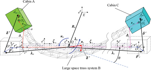
During the DSS attitude maneuvering and subjected to external perturbations, the large space truss structure is prone to vibration resulting in the joint vibration of module A and module C. According to the laws of conservation of momentum and kinetic energy, the position of the center of mass O of the system remains constant during the vibration process. The motion of module A and module C consists of two parts: One is the attitude maneuvering of the whole apparatus and the other is the vibration.
Let us define eE to be the geocentric inertial coordinate system, e0 to be the orbital coordinate system, ee to be the unitary body coordinate system, es to be the modular substructure coordinate system, and ea and ec to be module A and module C cemented coordinate system, respectively.
According to the structural characteristics of the DSS and the requirements of ACC, and following the basic idea of the graph theory, the DSS is divided into two control subsystems and ns modularized substructures, as shown in Figure 2. The modularized substructures contain three categories: The first category is the modularized substructure n1 connected to module A on the left side; the second category is the modularized substructure ni, i = 2, 3, ⋯, ns − 1 connected to trusses at both ends; and the third category is the modularized substructure ns connected to module C on the right side. Each modular substructure contains nsd nodes and nse units.
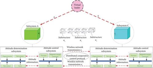
Each subsystem contains an attitude determination subsystem and an attitude control subsystem. The attitude determination subsystem contains magnetometers, sun sensitizers, star sensitizers, and gyroscopes to jointly complete the attitude measurement of each module. The attitude information is transferred to the attitude control subsystem. The attitude control subsystem solves the information from the attitude determination subsystem, and it solves the attitude information of the virtual leader and another module at the same time. Through the distributed attitude control protocol, control schemes such as output torque and output time of each capsule are determined, and attitude cooperative maneuvers are executed.
Based on the delineated submodules and subsystems, the following sections will establish the dynamics model applicable to distributed control.
2.3. Modeling of Subsystem Dynamics
In the formula, two types of vectors are introduced: The first one is denoted as λa, λe and λc, which represents the microelement vector diameter of each body from the center of mass of the system O to the deformation front, and the second one is denoted as δa, δc, and δe, which represents the displacement of the microelement body due to the vibration of the truss structure.
2.4. Actuator Faults Models
The term in Equation (25) is feedback to ensure that the estimates approach their accurate value. More details related to the variables used in this subsection are provided in [19].
The main objective of this paper is to achieve DSS attitude maneuvering while solving problems such as insufficient attitude stabilization and large vibrations caused by external disturbances, model uncertainties, and actuator failures. In order to achieve these aims, a CACC method is proposed in the following sections.
3. CACC Method
The main function of the CSVS is to meet the vibration requirements of the spacecraft while achieving attitude maneuvers. The advantage is that no other external control is required, and the vibration of the spacecraft can be effectively reduced. The disadvantage is that it cannot meet the vibration suppression in the case of actuator failure, model uncertainty, and external interference. The advantage of MPC is that it has good robustness and processes multiple inputs and multiple outputs at the same time, which is suitable for multivariable control problems. The disadvantage of MPC is that it does not consider the vibration of the system and cannot achieve the situation where the system has delays. It only achieves the optimal value of the target for the existing target. ACC mainly studies the attitude and vibration coordination of the two subsystems, without considering the attitude and vibration of the whole device. For DSS, we need to meet the attitude and vibration suppression of the system, the attitude and vibration suppression of the core module, and the payload module. On this basis, it is necessary to achieve attitude and vibration suppression in extreme cases such as external interference, model uncertainty, and actuator failure. The controllers that have been studied so far cannot achieve the above functions.
Combining the advantages of ACC, MPC, and CSVS, the proposed CACC will be given in this section, and the stability of the closed-loop system will be proved. The control principle is shown in Figure 3.

The traditional CSVS is improved, and a 7-segment CSVS is proposed. The purpose is to achieve the whole-vehicle vibration suppression and target attitude. The angular velocity calculated by the 7-segment CSVS is used as the input of the MPC. The two methods of CSVS and MPC are combined, the angular velocity of CSVS and the modal coordinates of the system are innovatively proposed as the state variables of MPC, and the segmented MPC method is proposed. The shortcomings of CSVS open-loop control are solved, and its advantages of vibration suppression are utilized. The segmented MPC is defined as the virtual leader of the system. Using the graph theory and cooperative control in Section 2.1, displacement coordination and velocity coordination are combined, and the consistency protocol of the core module, payload module, and virtual leader is proposed. On this basis, we consider the communication delay of the system and add a delay term to the distributed cooperative attitude controller. The overall control constitutes a CACC method. This method meets extreme conditions such as whole-vehicle attitude maneuvers, vibration control, actuator failure, and communication delay.
3.1. Component Force Synthesis Active Vibration Suppression Method
Theorem 3. For a damped second-order system (28) with zero initial conditions, if the damped vibration period is divided into n equal parts and a similar component force is applied at the beginning of each part or at an integer multiple of the damped vibration period from the beginning, then the system will be free of vibratory motion at the end of the force.
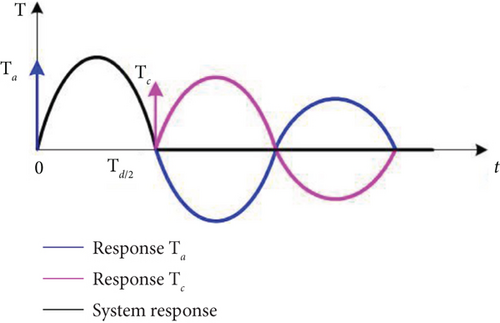
In Theorem 3, the key points are the onset and magnitude of the action of the similar component forces, and Figure 4 depicts the system vibration under the action of two similar forces. They act at the moments 0 and Td/2, respectively. The relationship between the two similar forces is . The system response due to the first component force (blue line in the figure) and the second component force (pink line in the figure) cancels each other after half a cycle, and the system will have no vibration.
The 7-segment reference angular velocity ωCSVS−j, j = 1, 2, ⋯, 7 based on the CSVS method can be obtained by Equation (32) for the ideal state spacecraft attitude maneuver command as shown in Figure 5.
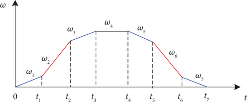
So far, we have designed similar split-force control instructions that satisfy the attitude maneuvering requirements of an ideal state spacecraft and achieve active vibration suppression of the system.
The CSVS method changes the form of the input signal so that the control torque is arranged along the time axis according to a certain rule to synthesize the new input of the system, thereby suppressing any multiorder modal vibration that has a greater impact on the system. In fact, it is a feedforward control method, and its anti-interference ability is relatively poor. When the system actuator fails or there is external interference, it is difficult for the CSVS method to obtain satisfactory results. In the MPC execution process, strategies such as multistep prediction, rolling optimization, and feedback correction are introduced to make up for the shortcomings of CSVS.
3.2. Segmented Model Predictive Control
By solving the optimization problem at each moment k, we can get the optimal control input sequence. The first element of the sequence is selected to act on the system, and the MPC control is realized by looping the above steps at the next moment.
In this section, the optimal control of the whole apparatus is designed by using MPC; in order to realize the cooperative control of the modules at both ends, the control of MPC is used as a virtual leader; and the distributed cooperative control is further used to improve the consistency of the module attitude maneuvers.
3.3. Synergistic Control
In the ACC, the consistency protocol is the focus of research, and the control outputs of the subsystems should have phase consistency with each other, that is, the same or opposite phase. Otherwise, it will lead to an increase in DSS vibration, which will seriously affect the attitude control accuracy of the satellite and lead to mission failure. Therefore, the following design includes a synergistic consistency term.
4. Closed-Loop System Stability Analysis
4.1. Preliminaries
The following lemmas are introduced to prove the stability of the closed-loop system.
Lemma 1 [22]. LlQqVv denote real matrices of appropriate dimensions; if is satisfied, the following inequality holds
Lemma 2 Schur’s lemma [23]. The symmetric matrix is given by
Lemma 3 KYP lemma [24]. Let Aa ∈ Rn×n, Bc ∈ Rn×m, and , and let det(jωI − Aa) ≠ 0, ∀ω ∈ (−∞, +∞). The following conditions are equivalent:
4.2. Stability Analysis
- 1.
Calculate the first row
- 2.
Calculate the second row
- 3.
Calculate the third row
- 4.
Calculate the fourth row
In inequality (86), all the parameters are known except for Ds. The inequality is solved according to the definition of infinite norm, only if the maximum of the absolute row sums of the inequality is less than 1. Inequality (86) holds, and then, inequality (82) holds.
According to Section 4.2, we can choose appropriate gain matrices by solving inequalities (68), (74), (80), and (86) independently. Then, it makes Equation (62) < 0 hold, and the closed-loop system is therefore asymptotically stable.
5. Simulation and Verification
In this section, the composite attitude cocontroller proposed in this paper is compared with existing controllers. The aim of this comparison is to determine the effectiveness of the proposed controller for attitude control and vibration suppression of a DSS. This determination is made under the conditions of ideal modeling, external disturbances, actuator failures, and communication delays.
The scenario considered is the reorientation of a spacecraft attitude maneuver (θy = 90°) for a science mission. In order to successfully accomplish the mission, the spacecraft must achieve a high attitude pointing accuracy in a limited amount of time. Three simulation scenarios are considered to reflect the superior performance of the proposed controller. The first scenario is the ideal model of the actuator without failure and external interference, that is, Td = 0 in Equations (13) and (14). The second scenario is the model of the actuator without fault and with external interference, and the external interference is set to be Tdy = 0.3sin(0.2πt) − 0.1cos(0.4πt) + 0.2N · m. And the third simulation scenario is the presence of actuator failure and communication delay. The dumbbell-shaped spacecraft structural parameters are mainly referenced by [2], and the data on failure rate, communication delay, and interference are derived from the actual project requirements. The structural parameters and control capabilities of the DSS are shown in Table 1.
| Component | Items(unit) | Value |
|---|---|---|
| Body A | Mass (kg) | 7000 |
| Length × width × height (m) | 6 × 3 × 3 | |
| Moment of inertia (kg·m2) | Diag (6000; 13,000; 13,000) | |
| Maximum output torque (N·m) | Tax = 20, Tay = 75, Taz = 100 | |
| Communication delay (s) | 0.1 | |
| Failure rate (%) | 0 ~ 20 | |
| Body C | Mass (kg) | 3000 |
| Length × width × height (m) | 2 × 2 × 2 | |
| Moment of inertia (kg·m2) | Diag (900, 8000, 8000) | |
| Maximum output torque (N·m) | Tax = 20, Tay = 75, Taz = 100 | |
| Communication delay (s) | 0.08 | |
| Failure rate (%) | 0 ~ 30 | |
| Boom truss | Mass (kg) | 1500 |
| Length × width × height (m) | 30 × 0.5 × 0.5 | |
| Moment of inertia (kg·m2) | Diag (152, 1.149e5, 1.149e5) | |
| Elastic modulus (GPa) | 72.7 | |
| Density (kg/m3) | 3100 | |
| Inner diameter (m) | 0.008 | |
| Outer diameter (m) | 0.012 | |
5.1. Case 1: Ideal Model
The ideal model refers to the ideal situation where there is no external perturbation, no model uncertainty, and no actuator failure. Using ANSYS finite element analysis software to establish the model of the truss structure, frequency and vibration patterns are analyzed in this paper for comparison, with the results shown in Table 2. The difference of the first six orders of frequency is less than 2%. The first six modes have the same vibration pattern, the fourth and sixth modes are torsion modes, and the rest of the modes are bending modes. The correctness of the dynamic model in this paper is fully proven.
| Modal | ANSYS result (Hz) | This paper’s result (Hz) | Error (%) |
|---|---|---|---|
| 1 | 2.904b | 2.904b | 0.02% |
| 2 | 7.846b | 7.856b | 0.13% |
| 3 | 14.897b | 14.968b | 0.47% |
| 4 | 15.914t | 16.018t | 0.65% |
| 5 | 23.519b | 23.808b | 1.21% |
| 6 | 31.286t | 31.896t | 1.91% |
- bBending mode.
- tTorsional mode.
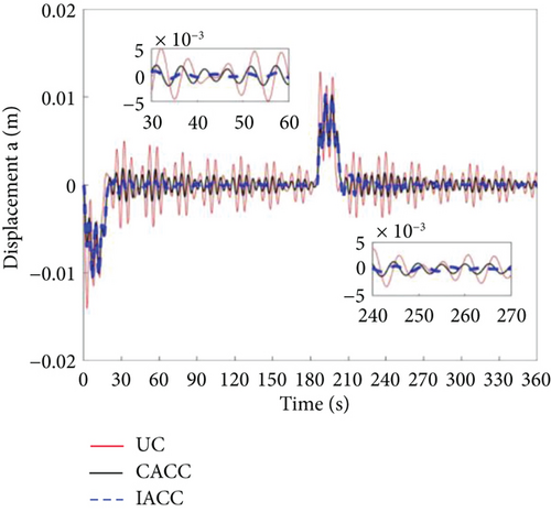
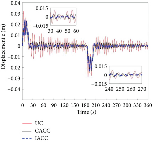
The state change curves of the attitude maneuvering process for the ideal model uncontrol (UC), ACC combined with component synthesis vibration suppression method (CACC), and improved attitude cooperative control (IACC) are shown in Figures 6, 7, 8, 9, 10, and 11.
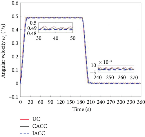
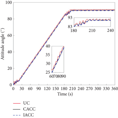
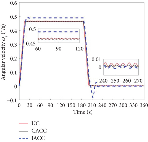
The attitude angular velocity of the DSS is presented in Figure 6, demonstrating that the IACC outperforms both the CACC and UC strategies. As shown in Figure 7, during the attitude maneuvering process from 0 to 203.6 s, the UC strategy exhibits significant attitude angle oscillations, particularly in the acceleration and deceleration phases. While the CACC strategy performs better than UC in mitigating these oscillations, the IACC approach achieves both attitude stabilization and vibration suppression throughout the maneuvering process and after 203.6 s. The UC strategy follows a traditional bang-off-bang control approach, designed primarily to satisfy attitude maneuvering requirements. However, owing to the high flexibility of large space truss structures, attitude maneuvers generate significant vibrations with minimal inherent damping, leading to prolonged oscillations in attitude angular velocity and angle. These oscillations cannot dissipate within a short period, adversely affecting spacecraft operations. The CACC strategy incorporates the CSVS method, which actively suppresses vibrations under ideal conditions, resulting in better performance than UC. The IACC method, building on CACC, integrates the MPC approach to optimize attitude angular velocity and modal coordinates, further enhancing vibration suppression compared to CACC without MPC.
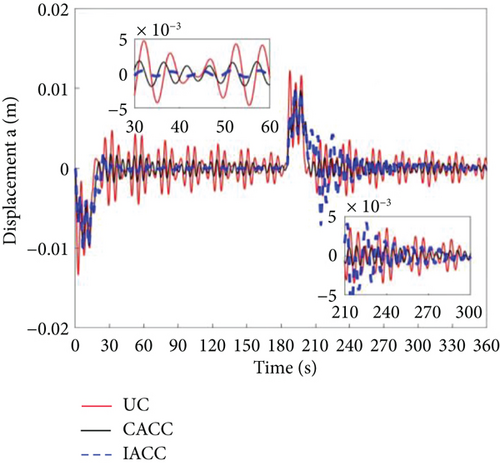
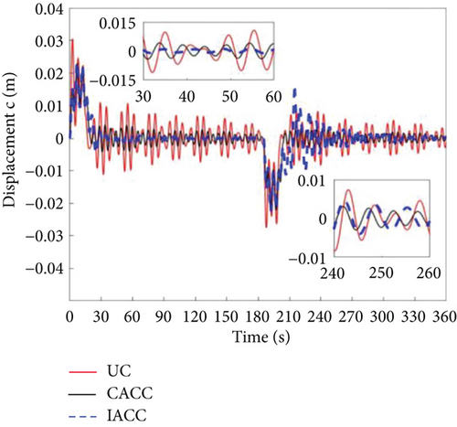
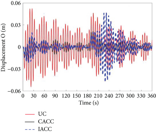
As shown in Figure 8, the vibration displacement amplitude of the active end of the dumbbell-shaped spacecraft under UC is 0.013 m. The amplitude under CACC is 0.011 m, and the amplitude of the IACC method we proposed is 0.0097 m. These data indicate that the vibration suppression effect of the IACC method is improved by 31.96% compared with that of UC and by 13.40% compared with that of CACC. Figure 9 shows that the vibration displacement amplitude of the passive end under UC is 0.029 m. Also, according to Figure 9, the vibration amplitude of CACC is 0.023 m, and the vibration amplitude of the IACC method is 0.022 m. The amplitude under UC is 29.55% higher than that of CACC and 5.45% higher than that of IACC. The same comparison was conducted at the center of mass of the system. As shown in Figure 10, the vibration amplitudes for UC, CACC, and IACC are 0.055, 0.022, and 0.021 m, respectively. Regarding the vibration displacement amplitude of the center of mass of the dumbbell-shaped spacecraft system, our proposed IACC method has a vibration suppression effect. This vibration suppression effect of the IACC method is 61.82% higher than that of the UC method and 4.76% higher than that of the CACC.
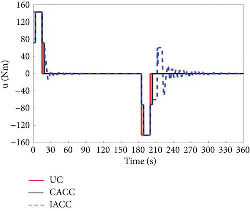
Additionally, the vibration amplitude in the A compartment is lower than in the C compartment and the system’s center of mass, making the A compartment more suitable for housing precision instruments. As illustrated in Figure 11, following the attitude maneuver, the IACC torque remains active from 203.6 to 270 s under residual attitude and vibration effects before transitioning into the attitude stabilization phase. This behavior results from the flexible truss structure’s vibration during the maneuver, which induces oscillations in both Body A and Body C. Without control, these vibrations exhibit large amplitudes and extended decay times. The core principle of CACC involves modifying the input signal and systematically arranging the synthesized system’s input over time to effectively suppress vibrations. Consequently, CACC successfully mitigates vibrations in both Body A and Body C. The IACC method further incorporates modal optimization, where the optimal modal value is zero. As a result, the vibration suppression effect of IACC surpasses that of both CACC and UC.
5.2. Case 2: With Perturbed Model Calibration
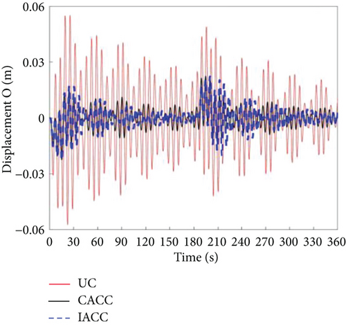
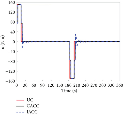
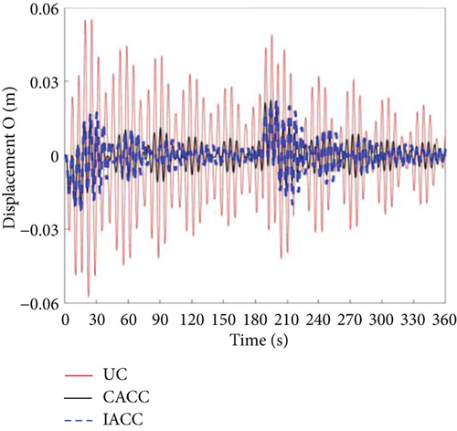
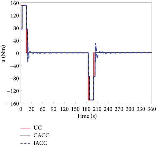
Considering that the dumbbell-shaped spacecraft may encounter periodic disturbances during the on-orbit attitude maneuvers, this case adds periodic disturbances in the range of 0 to 360 s based on the ideal model. The simulation results are shown in Figures 12, 13, 14, 15, 16, and 17.
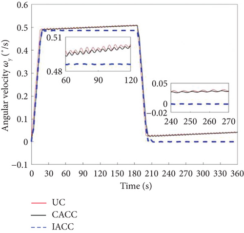
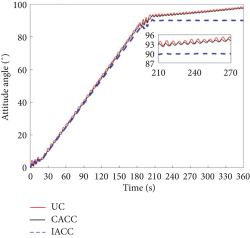
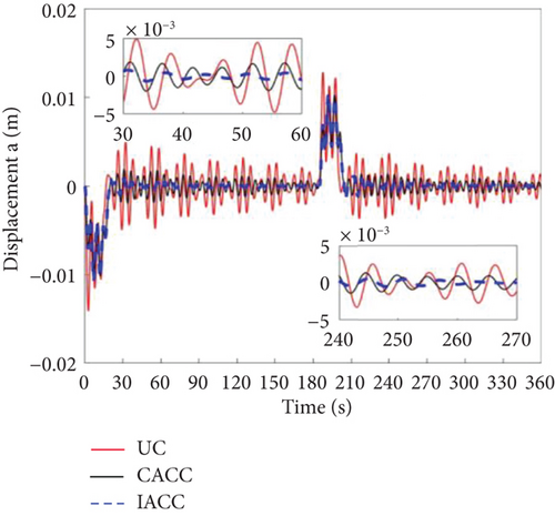
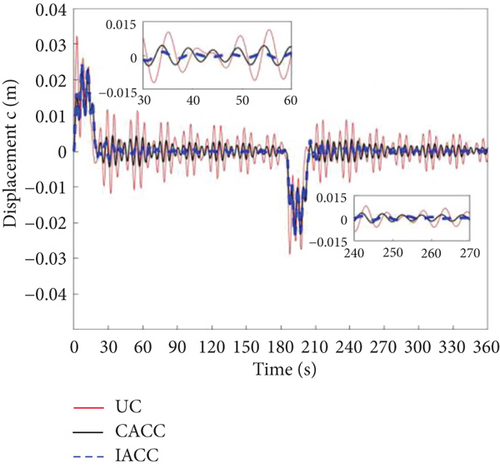
Figures 12 and 13 present the simulation results for the attitude angular velocity and attitude angle of the three control modes under periodic disturbances in the DSS. It is evident that the vibration amplitude of CACC is significantly smaller than that of UC during the attitude maneuver, demonstrating that CACC effectively suppresses vibrations even under periodic disturbances. However, neither UC nor CACC satisfies the requirements for precise attitude maneuvers. This is primarily because both strategies are open-loop control methods. When the system experiences disturbances, the attitude angle and angular velocity deviate from their nominal values. A key limitation of open-loop control is its inability to correct these deviations. Additionally, the vibrations induced by the flexible truss structure lead to instability in the attitude angle and angular velocity, making it impossible to achieve accurate attitude control of the dumbbell-type spacecraft. The IACC method proposed in this study integrates a segmented MPC control strategy with the CSVS strategy, functioning as a feedback control approach. As a result, IACC can correct deviations in the attitude angle and angular velocity when disturbances occur, ensuring that both the target attitude angle and mode are optimized. The global optimum is attained under segmented optimum conditions. Consequently, under periodic disturbances, IACC significantly outperforms both UC and CACC in terms of performance.
Figures 14, 15, and 16 illustrate the vibration conditions of Body A, Body C, and the vehicle’s center of mass, respectively. During on-orbit operation, the periodic disturbance torque is substantially smaller than the attitude maneuvering torque, and thus, the disturbance has a minimal impact on vibration. The primary source of vibration stems from the torque associated with attitude maneuvers. Between 205 and 215 s, the vibration in the IACC strategy is slightly greater than in CACC. This is because IACC actively corrects the spacecraft’s attitude to meet the required specifications, while CACC does not make any corrections during this period. This observation is further validated by the torque outputs shown in Figure 17. After 215 s, the vibration amplitude in the IACC strategy gradually decreases, demonstrating that the segmented MPC combined with CSVS effectively and rapidly suppresses vibrations, facilitating successful attitude maneuvers despite external disturbances.
5.3. Case 3: Actuator Failure Model Validation
Consider the possible failure of the actuator during the actual in-orbit flight. This case analyzes the situation when the actuator failure rate is 5%; that is, the actual output moment of the vehicle is 95% of the theoretical output moment magnitude. Figures 18 and 19 show that the UC and CACC strategies cannot achieve the required attitude maneuver. In contrast, the IACC strategy proposed in this paper can well achieve the 90° attitude maneuver, and at the same time, its attitude stability can meet the design requirements of the vehicle.
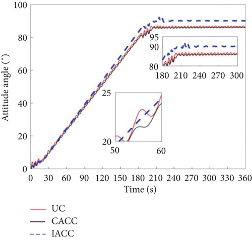
The fundamental difference between the UC and CACC strategies lies in their underlying mechanisms. UC operates as a bang-off-bang control, while CACC combines cooperative control and CSVS control, both of which are open-loop strategies. In the event of an actuator failure, neither UC nor CACC can generate the expected control torque, leading to attitude errors during the acceleration, uniform speed, and deceleration phases. The accumulation of these errors ultimately prevents the target value from being reached, thereby demonstrating that open-loop control is insufficient to satisfy the requirements for attitude maneuvering under actuator failure. The IACC strategy proposed in this study, however, incorporates a 7-segment CSVS method to suppress vibrations caused by attitude maneuvers, generating 7-segment time and 7-segment angular velocity. These are then input into the MPC as state variables. Additionally, the residual vibration that cannot be suppressed by CSVS is considered, and the mode is treated as another state variable. This approach enhances vibration suppression. In the event of an actuator failure, the control duration of IACC exceeds that of both UC and CACC. This extended control time is attributed to the failure of the actuator, which prevents the execution of attitude maneuvers based on the original maximum value. Therefore, a 90° attitude maneuver requires more time than under normal conditions.
Figures 20, 21, and 22 illustrate the vibration displacements of Body A, Body C, and the system’s center of mass when the actuator failure rate is 5%. The graphs show that between 0 and 30 s, the vibration amplitude of IACC is greater than that of CACC but smaller than that of UC. This is due to the segmented vibration suppression mechanism based on CSVS in IACC, which suppresses most of the vibrations. However, actuator failure leads to deviations in the output torque, which causes continuous adjustments in torque size and timing under the influence of segmented MPC and cooperative control, resulting in an increase in system vibration amplitude. Figure 23 demonstrates that at 30 s, the change in IACC is greater than that in both UC and CACC, supporting this observation. Similarly, between 210 and 240 s, the vibration displacement of IACC is larger, and the vibration amplitude exceeds that of UC and CACC. The vibration amplitude of the system’s center of mass is significantly greater than that of Body A and Body C. This disparity arises because Body A and Body C have larger masses. According to the principles of momentum and kinetic energy conservation, the larger the mass in a system, the smaller the vibration amplitude. At the end of the deceleration phase of the attitude maneuver, IACC automatically adjusts the magnitude and timing of the applied torque to satisfy the attitude requirements. However, neither UC nor CACC can fulfill the attitude maneuver requirements in the event of actuator failure.
6. Conclusions
This study introduced the IACC algorithm, which was designed to achieve high-precision attitude maneuvering and vibration suppression in DSS. The attitude and vibration equations of the DSS were systematically derived, along with the dynamic equations of its subsystems and substructures. The modeling process accounted for critical factors such as external disturbances and actuator failures. The proposed IACC strategy was detailed to ensure effective attitude maneuvering and vibration suppression under these conditions. The stability of the IACC system was verified using the Lyapunov method. Under ideal simulation conditions, attitude stabilization improved by 10% and 40% compared with CACC and UC, respectively. In the presence of external disturbances, IACC achieved the required attitude maneuvering and stabilization, which neither UC nor CACC could accomplish. In the case of actuator malfunctions, IACC met both high-precision attitude maneuvering and vibration suppression requirements. At the end of the deceleration phase, a slight increase in vibration was observed. However, the vibration displacement in the A compartment was 60% lower than that in the C compartment, enabling the installation of more sophisticated payloads in the A compartment.
Future research will focus on conducting experimental validation once test conditions are met. Additionally, efforts will be directed toward optimizing energy consumption. The aim is to extend the applicability of this method to other related fields, thereby further advancing scientific research.
Conflicts of Interest
The authors declare no conflicts of interest.
Funding
This work is supported by the National Natural Science Foundation of China (Grant No. 62373122).
Acknowledgments
This work is supported by the National Natural Science Foundation of China (Grant No. 62373122).
Appendix A
Appendix B
Open Research
Data Availability Statement
Some or all data, models, or codes that support the findings of this study are available from the corresponding author upon reasonable request.


