A Review on High-Speed Electromagnetic Flow Control and Applications Considering Numerical Methods, Simulations, and Experimental Research Data
Abstract
Background: Electromagnetic flow control is crucial in hypersonic gas dynamics, with key aspects of boundary layer electromagnetic flow control reviewed, focusing on numerical methods, simulations, and experimental research.
Numerical Methods: Challenges such as numerical stiffness and instability arise from the coupling of electromagnetic fields with fluid dynamics. To address this, conservative magnetohydrodynamic (MHD) equations are developed, enforcing the magnetic field’s zero-divergence condition. Additionally, turbulence models must account for electromagnetic effects on turbulence dissipation, and electrical conductivity needs accurate modeling for improved simulation precision.
Simulations: The mechanisms of magnetically controlled flows are analyzed, with parametric studies on electromagnetic field strength, orientation, and positioning summarized. Emphasis is placed on optimizing field distribution, particularly in shock wave–boundary layer interactions. Further research on three-dimensional effects and complex configurations is recommended.
Experimental Research: The current development of high-enthalpy wind tunnels is reviewed, highlighting their potential to simulate real flight conditions. However, improvements in facility speed and magnetic field strength are required. Advanced simulation technologies and superconducting magnet optimization are essential for effective flow control, alongside addressing the Hall effect in MHD systems.
1. Introduction
Electromagnetic flow control (EMFC) has broad engineering applications in the aerospace field, including the redistribution of pressure and heat flux on aircraft surfaces, optimization of the heat and momentum distributions within engine ducts, enhancement of the mixing of fuel/air in scramjet/ramjet combustion chambers, onboard EMFC power generation, and boundary layer control.
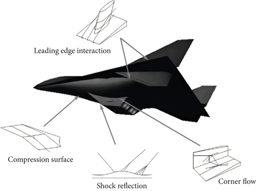
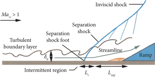
The accuracy of simulating hypersonic flow mainly depends on the accuracy of simulating shock wave–boundary layer interaction (SWBLI). Hypersonic SWBLIs can be characterized by unsteady vortex shedding and flow separation, whereby local pressure elevations and boundary layer thickening are induced [1, 2]. Viscous phenomena are amplified, through which rapid expansion of the dissipation region is facilitated, turbulence fluctuations are enhanced, wall pressure loads are intensified, pressure recovery coefficients are diminished, and localized thermal flux and aerodynamic resistance at the wall are augmented. The archetypal manifestations of SWBLI on hypersonic vehicles and the characteristic flow configurations of compression corners, including shock/turbulent boundary layer interactions (STBLIs), under supersonic conditions are depicted in Figures 1 and 2, respectively.
EMFC, as a shock–boundary layer interaction control technology, is characterized by high efficiency, simplicity in structure, and the ability to open and close as needed. Its control mechanism involves using the Lorentz force generated by the electromagnetic field to control the fluid motion. By varying the magnetic field, the Lorentz force can be modified, thereby altering wall heat flux or temperature, incoming mass flow rate, or determining a new boundary shape.
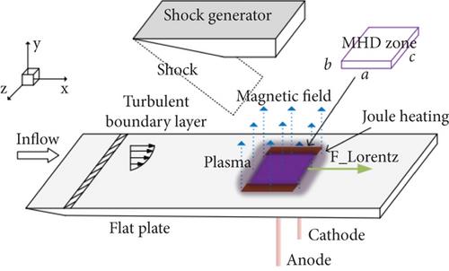
Figure 3 illustrates the principle of EMFC. When a shock interacts with a turbulent flat-plate boundary layer, a sliding electric arc discharge is employed to induce local ionization and directed current near the wall. Additionally, an applied magnetic field generates directed Lorentz forces to control the flow.
The classic Hartmann flow [6], as Figure 4 shows, which involved experimental research on the flow characteristics of mercury in a uniform magnetic field, was the first to discover the influence of an external magnetic field perpendicular to the flow direction on the turbulent friction in channels and its inhibitory effect on turbulence. Through the method of “artificial ionization” using local magnetic control, as shown in Reference [7], turbulent boundary layer separation has been effectively suppressed. Through Hartmann flow, Reference [6] confirmed the decelerating effect of Lorentz forces on flow and its impact on the boundary layer. Near the boundary layer, where viscous forces are significant and velocity is low, Lorentz forces are relatively small due to the larger velocity gradients, resulting in the formation of the Hartmann layer. However, in the middle region between the two flat plates, where viscous effects are smaller, Lorentz forces generated by the magnetic field can counteract pressure gradients and viscous forces, achieving the goal of flow deceleration.

The effectiveness of additional electromagnetic field shock–boundary layer disturbance control can be characterized by variations in pressure, heat flux, skin friction, fluid acceleration/deceleration, changes in the length of the disturbance zone, alterations in the primary characteristics of the boundary layer, and shifts in separation conditions. Therefore, boundary layer control can be achieved by regulating flow separation, transition point locations, and other factors [1].
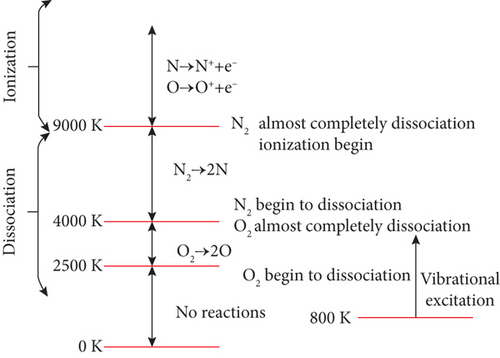
There are three main factors affecting the effectiveness of MHD flow control/Lorentz forces: magnetic field, conductivity, and flow velocity. Regarding the magnetic field, the onboard magnetic field is typically only a few Teslas, and increasing the magnetic field excessively is not practical. For conductivity and flow velocity, when the flight Mach number Ma < 12, the temperature in the flow field is insufficient to generate a sufficient amount of plasma through thermal ionization, making it impossible to achieve the necessary conductivity for magnetohydrodynamic flow control. Therefore, it is necessary to develop artificial ionization techniques to generate plasma for magnetic fluid control. This type of control is known as plasma excitation control. Typical plasma excitation methods include dielectric barrier discharge (DBD), surface corona discharge (SCD), and plasma spark-jet actuators [8]. These methods can be used to enhance ionization through surface alkali metal salt augmentation or electron beam excitation, among other techniques. As shown in Figure 5, when the air temperature exceeds 9000 K, oxygen and nitrogen atoms ionize to form localized thermochemical nonequilibrium plasma [6, 10]. At this point, the air becomes an excellent conductor and can be directly subjected to external electric fields or coupled with self-generated electromagnetic fields for electromagnetic excitation control. The addition of an external electric field can further enhance flow control effectiveness [7].
Sufficient air ionization is generated in the region behind SWBLI following shock wave recompression, forming a plasma flow field with higher conductivity that can be controlled by electromagnetic fields. Figure 6 illustrates the principle of magnetically controlled SWBLI.
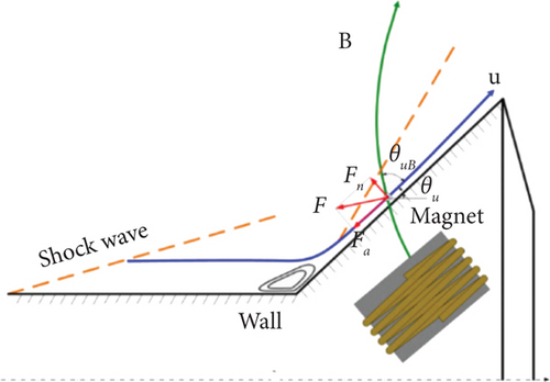
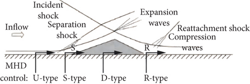
Figure 7 displays that magnetically controlled SWBLI can be categorized into four types: U-type (upstream), S-type (separation), D-type (downstream), and R-type (reattachment) [11]. Among them, U-type control is achieved by increasing the momentum of the upstream boundary layer, reducing incoming turbulent boundary layer thickness and displacement thickness; the control area of S-type extends upstream from the separation point; the control area of D-type is entirely within the separation region; R-type indicates the region of influence passes through the reattachment point.
To maintain the maneuverability of hypersonic aircraft, EMFC is required for the two-dimensional and three-dimensional effects of SWBLI occurring near control surfaces and inlets. Zheng and others studied electromagnetic control in nondesign conditions and found that the disturbance region near the cowl lip had the greatest impact on control performance [12].
Others researches on boundary layer separation control and drag reduction through Lorentz forces have been carried out [13, 14]. The efficiency of streamwise electromagnetic forces and spanwise oscillatory Lorentz forces in drag reduction was studied, and streamwise electromagnetic forces were proved to be highly effective, but meanwhile, it consumes more energy, necessitating further improvements in the efficiency of EMFC [15]. MHD control of inlet boundary layer separation has also been investigated, with results indicating that streamwise Lorentz forces played a primary role in eliminating separation [16].
2. Magnetic Flow Control Mechanism
2.1. Dynamic Effects
Dynamic effects refer to the directed motion of plasma formed by ionization in the flow field or added plasma under the influence of electromagnetic forces. It induces the motion of neutral gas molecules through momentum transport between ions and neutral gas molecules, resulting in plasma aerodynamic excitation [9].
Based on numerical simulations under the baseline conditions of an ICP (inductively coupled plasma) wind tunnel, high-frequency discharges and nonequilibrium flow characteristics in the presence of electromagnetic fields were revealed [17]. The results indicated that in the vicinity of the plasma wall near the induction coil, the plasma flow was in a thermodynamically nonequilibrium state. The Lorentz force controlled the momentum transfer of air particles in the induction coil area and the thermal motion of electrons.
An EMFC inlet shock wave method was proposed based on plasma excitation and electron beam ionization [18, 19]. This model aimed to enhance air capture under off-design Mach numbers, as represented in Figure 8:
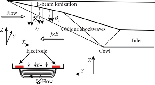
The results showed that when the flight Mach number exceeded the design Mach number, selecting appropriate magnetic field parameters could increase air capture and reduce total pressure losses. However, for Mach numbers below the design value, the action of Joule heating resulted in reduced air capture and increased total pressure losses.
Building upon this, a novel magnetic controlled inlet for high Mach number flight was designed using a two-stage compression model, as shown in Figure 9 [20]:
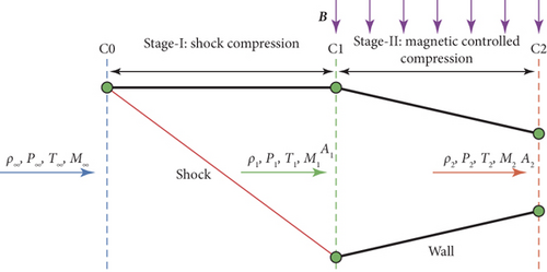
The applied magnetic field was situated inside the inlet’s internal channel, ensuring that adjustments to the magnetic field did not affect upstream shock waves. By magnetically controlling the shape and position of the upstream shock wave, reflected shock waves within the inlet’s channel could be eliminated, significantly reducing the complex SWBLI typically found in conventional inlets.
This design approach achieved the desired lip shock wave configuration. Although total pressure recovery decreased significantly, some of the energy loss could be converted into electricity through EMFC energy extraction devices, which was then used to accelerate the nozzle flow.
The study highlighted that, besides the MHD turning effect, the compressibility capability of magnetic fluid was crucial for improving the operating Mach numbers of propulsion systems. Magnetic compression, replacing traditional shock wave compression, was supported by the deceleration effect of the Lorentz force.
Subsequently, the study focused on a quasi-one-dimensional simplified model of the inlet, further analyzing the compressibility performance under different magnetic field conditions (0.05, 0.08, and 0.1 T) and combinations of upstream shock wave angles. The results indicated that a small shock wave angle combined with a strong magnetic field exhibited the best deceleration performance, whereas larger shock wave angles led to higher pressure ratios and lower temperature ratios under strong magnetic fields. The total pressure recovery coefficient was primarily influenced by magnetic compression, with shock wave losses caused by the upstream shock wave having limited impact. Therefore, striking a balance between shock wave compression and magnetic control compression was a key aspect of magnetic inlet design.
2.2. Changes in Physical Properties
Changes in physical properties refer to alterations in the thermophysical characteristics of airflow, such as density, viscosity, and thermal conductivity, induced by the presence of plasma in the flow field.
There are variations in shock tube density before and after the application of an external magnetic field as depicted in Figure 10 [6]:

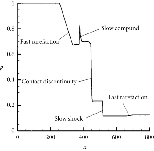
Density-based representations were used to illustrate the changes in the internal flow structure of the shock tube. In the absence of a magnetic field, the flow in the shock tube could be precisely solved using the classical Riemann problem. From left to right, this resulted in the formation of a leftward-expanding rarefaction wave, a contact surface, and a rightward-propagating shock wave.
3. Models and Computational Methods
3.1. Control Equation and Boundary Conditions
Currently, the core research contents of models and numerical methods for EMFC simulations are summarized in Table 1:
| Year and author | Research contents |
|---|---|
| Wang (2014) [21] | Implicit treatment of SA turbulence model and k-ωSST turbulence model |
| Tong (2018) [22–25] | Improvement of SA turbulence model using DNS data |
| Song (2017) [26] | Development of compressible turbulence model CKDO based on the improved KDO turbulence model for simulating shock wave–turbulence boundary layer interaction |
| Duraisamy (2017–2019) [27, 28], Ling [29], Wang (2018) [30], and Wu (2017) [31] | Modification of turbulence models and establishment of mappings between neural networks and correction terms through machine learning (e.g., neural networks) to obtain embedded turbulence models |
| Raissi (2019) [32, 33] and Zhang (2020) [34] | Data-driven modeling to enhance the predictive accuracy of turbulence models (various optimization methods including neural networks, discrete adjoint methods, etc.) |
| Jiang (2022) [11, 35] | Coupling of turbulence models and high-temperature gas models (without considering the influence of turbulence on component generation rate), using Gupta11 component 20 chemical reaction model, thermochemical nonequilibrium gas model, and dual-temperature model |
| Yee (1966) [36, 37], Balsara (2001) [38, 39], Brackbill (1980) [40], Powell (1994) [41], Dedner (2002) [42], Brecht (1981) [43], Dai (2022) [44, 45], and Tóth (2000) [46] | Research related to magnetic field divergence cleaning |
| Sávio (2017) [47], Lykoudis (1967) [48], and Chen (2010) ([49]; [50]) | Magnetohydrodynamic corrections based on turbulence models |
| Fan (2016) [51] and Jiang (2022) [11, 35] | Simulation of magnetohydrodynamic turbulence using RANS methods |
| Shimomura (1991) [52], Kobayashi (2006) [53], and Bisek (2013) [54] | Simulation of magnetohydrodynamic turbulence using large eddy simulation (LES) methods and the establishment of magnetohydrodynamic turbulence correction models |
| Damevin (2001) [55] and Augustinus (1997) [56] | Numerical simulation of magnetohydrodynamics using TVD methods and R-K formats |
| Han (2011) [57] | Application of the AUSM series numerical methods in magnetohydrodynamic research |
| Otsu (2006) [58, 59] | Numerical simulation of three-dimensional spherical head hypersonic low magnetic Reynolds number MHD flow using ASUM-DV format |
| He (2005) [60] | Development of a magnetohydrodynamic numerical solution method based on the NND format |
| Su (2009) [61] | Study of MHD-induced turbulence boundary layer separation using a weighted form of the third order ENN format—WENN format |
- 1.
The numerical stiffness and singularity issues arising from the high-temperature thermochemical nonequilibrium multicomponent gas model. Solving the numerical stiffness of a multicomponent high-temperature thermochemical nonequilibrium gas model is challenging. Two approaches can be considered to tackle this issue. First, the nonequilibrium source terms can be separated and solved separately from the control method. While this method introduces additional errors and offers only first-order accuracy in time discretization, it helps mitigate the numerical stiffness. Second, coupling the nonequilibrium terms with the inviscid and viscous terms for simultaneous solution is a more computationally intensive approach but may yield better results.
- 2.
Issues related to turbulence models. The right-hand source terms of turbulence models serve a dual purpose. On the one hand, they can effectively capture the spatial scales and temporal high-frequency fluctuations of turbulence [62]. However, on the other hand, they lead to complex variations in the mathematical properties of equations, giving rise to convergence difficulties, unstable iterations, and a series of numerical stiffness problems. From the perspective of equation stability, these issues necessitate a separate analysis of the local time steps for convection, diffusion, and source terms when determining the time step. Additionally, stricter constraints should be placed on grid aspect ratios, mesh density, and related factors. Nevertheless, it is important to note that these measures inevitably result in a significant reduction in the convergence rate of the governing equations. According to Reference [63] in many cases, even with these precautions, serious convergence oscillations and unphysical solutions may still arise. Furthermore, different decomposition terms and the introduction of external electromagnetic fields also require adjustments to the turbulence models.
- 3.
Numerical stiffness and divergence conditions introduced by the magnetic field. Introducing a magnetic field adds Maxwell’s equations for electromagnetic fields and interaction terms between magnetic and flow fields to the MHD equations. Directly coupling and solving the govern equations introduce significant stiffness issues. In cases of low electrical conductivity, the magnetic diffusion term becomes a major source of numerical instability. The magnitude of the magnetic diffusion term increases substantially with lower electrical conductivity, causing the equation to transition from hyperbolic to parabolic near the diffusion limit. Numerical stiffness accumulates and leads to nonconvergence, requiring a reduction in the CFL number and increasing computational time. Therefore, it is advisable to avoid solving this type of equation and instead use a low magnetic Reynolds number approximation equation. Lower magnetic Reynolds numbers imply that the influence of induced magnetic fields can be ignored, and the added magnetic field is not disturbed by the flow field. The magnetic transport equation can be removed from the equation group. The influence of an external magnetic field on the flow field can be represented by adding some source terms to the fluid mechanics equation group.
Furthermore, when coupling the flow field with the electromagnetic field, the nonconservation of equations may introduce errors, leading to divergence during solving. Therefore, careful attention should be given to enforcing divergence cleaning conditions during the solution process.
3.1.1. Computational Stiffness and Equation Singularity
The modeling of high-enthalpy, high Mach number airflow under hypersonic conditions was established by the von Karman Institute [64]. They proposed a novel quasiequilibrium flow effective asymptotic model. Through comparison with the results of chemical nonequilibrium (CNEQ) flow calculations, they verified the effectiveness of this model. A comprehensive assessment of chemical kinetics and energy exchange models for thermochemical nonequilibrium flows was performed. Regarding chemical kinetics, the most reliable dataset for reaction rate constants is the Park dataset. However, concerning vibration/chemistry coupling, Park’s model is correlation-based, making it effective under certain conditions but potentially failing under others. Direct numerical simulations of hypersonic flat-plate turbulent boundary layers under both thermal equilibrium and chemically nonequilibrium conditions using the high-speed Navier–Stokes equations were conducted [65, 66]. The results indicated that the high-enthalpy turbulent boundary layer can directly employ transformations such as Van Driest’s velocity and Morkovin’s scaling theory, based on fully gas conditions. Pan and others studied hypersonic chemically nonequilibrium MHD flow, employing a simplified 5-species 17-reaction model for chemical kinetics [67]. Jiang et al. [11] investigated turbulent flows considering high-temperature gas effects under the influence of an external electromagnetic field. This study also considered high-temperature gas effects and turbulence in hypersonic shock–boundary layer interactions. It utilized the Gupta 11-species 20-reaction chemical reaction model, thermochemical nonequilibrium gas model, and two-temperature model, resulting in improved accuracy of the computational results. However, in this research, the influence of turbulence on the species production rate in the component equations was not considered. The chemical reactions were modeled using a finite-rate reaction model, and the mean quantities were directly used when calculating reaction rates. Therefore, the coupling model for the chemical reaction rates in high-enthalpy turbulence remains an unresolved issue [47, 67].
Currently, the methods used in research often involve making certain assumptions or simplifications in thermodynamic or gas models. However, such computational results often exhibit significant discrepancies when compared to real-world scenarios.
3.1.2. Turbulence Model-Related Issues
3.1.2.1. Stiffness
A common approach to addressing the stiffness issues associated with turbulence models is to apply implicit treatment to the source terms [67]. Wang et al. applied point implicit treatment to turbulence models, specifically the SA turbulence model with weaker source term stiffness and the k-ωSST turbulence model with stronger source term stiffness. The significance of the balance between production and dissipation terms for numerical simulations is discussed, and specific methods for handling different source terms are provided; the results with the RAE2822 airfoil transonic flow case are validated as well [21].
Jiang et al. [11] conducted numerical simulations of high-speed multifield coupled shock–boundary layer interactions. In this study, modeling treatment was applied to high-temperature turbulence fluctuations. Reference was made to the Reynolds time-averaged derivation and linear modeling of vorticity–viscosity terms under fully gas conditions. A unified approach treating the transport effects of various components on turbulence fluctuations as a mixture component was used to simplify the treatment for air under fully gas conditions. The study considered the coupling of turbulence with molecular vibration and CNEQ but did not consider potential coupling effects between turbulence models and high-temperature gas models, specifically the coupling of transport coefficients, specific heat ratios, and other parameters to turbulence fluctuations.
3.1.2.2. Turbulence Model Modifications
In recent years, there has been a growing trend to introduce data-driven and machine learning methods for modifying turbulence models in Reynolds-averaged Navier–Stokes (RANS) turbulence simulations [26, 68]. These methods are collectively referred to as data-driven modeling approaches. Parish et al. [69] and Singh et al. [70] used flow field inversion to obtain modifications for turbulence models and then employed neural networks to establish the mapping relationship between flow field features and the modifications, resulting in embedded turbulence models. The reconstructed turbulence models provided results that closely matched experimental data. Ling et al. [29] utilized computational results from DNS and LES to develop machine learning–enhanced RANS turbulence models. They compared different machine learning methods such as support vector machines, decision trees, and random forests in predicting flow field uncertainties. The results demonstrated that these methods accurately captured flow characteristics even in cases differing from the training samples. Xiao et al. [71] applied Bayesian methods to quantify the uncertainty in model forms for RANS calculations and incorporated empirical knowledge constraints. The method effectively utilized sparse prior data to capture errors in baseline models and achieve more accurate posterior mean velocity distributions. Wang et al. [72] highlighted the importance of Reynolds stress prediction in determining RANS calculation accuracy. They developed a random forest machine learning reconstruction method based on the Reynolds stress tensor and applied it to turbulence modeling for flows in square ducts and typical separated flows. Wu et al. [31] adopted a similar approach to construct random forest models and provided prior estimates of confidence for RANS calculations. Zhu et al. [73] constructed radial basis neural networks for different regions in the near-wall and wake regions of airfoils. They modeled the Reynolds stress contributions in high Reynolds number turbulent boundary layers and introduced them in real time into the flow field solution process, improving the calculation accuracy. This approach demonstrated a certain degree of generality for various airfoil shapes and flow conditions. In the field of turbulence simulations, data-driven machine learning methods based on large datasets hold great promise, as reviewed in Reference [28], although data-driven turbulence modeling methods based on physical knowledge constraints for RANS turbulence simulations have not been identified.
Zhang et al. [34], while investigating the decomposition of turbulent friction drag using DNS data, identified a consistent scaling relationship for the decomposition terms within the inner layer of the turbulent boundary layer. Building upon this physical insight, they conducted data-driven modeling and modification of the S-A turbulence model, incorporating physical knowledge constraints during modeling.
They compared the impact of modifications with and without physical knowledge constraints on the accuracy of predicting turbulent friction drag in channel flows. The study employed a discrete adjoint method for the optimization of turbulence models, and the optimization process is outlined in Figure 11.
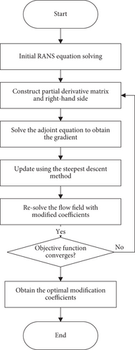
3.1.2.3. Coupling of Turbulent Flow and Electromagnetic Fields
Turbulence can influence the confinement conditions of plasmas [74]. When a weak field acts on the plasma, turbulent collisions have a significant impact on the electromagnetic properties of turbulent plasmas. This implies that by increasing the turbulence of the plasma, one can alter the growth rate of plasma instabilities, thereby changing the electromagnetic properties of the fluid, especially for external fields with disturbances or frequencies much lower than the characteristic turbulent collision frequency. In such cases, the dielectric constant cannot be extended based on turbulent energy, making the change in electromagnetic properties crucial. This effect can be described by the dielectric constant that depends on turbulent energy.
Sávio and Andrade [47] conducted research on magnetically driven turbulent reentry flows under thermochemical nonequilibrium conditions. This study marked the first application of coupling chemical reactions with turbulent flow fields and magnetic fields. Using Maciel’s [47] numerical algorithm and structured spatial discretization methods, they coupled the Favre-averaged Navier–Stokes equations with the Maxwell equations.
Su et al. [61] used a high-order difference scheme (weighted form of third-order ENN format: WENN1) to solve the magnetohydrodynamic turbulent equations for low magnetic Reynolds number approximation while studying EMFC accelerated boundary layers. The B-L turbulence model was adopted, along with the Degani–Schiff modification. Using this high-order difference program, they systematically investigated the effect of EMFC accelerated boundary layers on SWBLIs.
Yuehua et al. [51] conducted numerical simulations of magnetohydrodynamic turbulence using RANS models. They concluded that for flows with a magnetic field perpendicular to the wall, the streamwise velocity inside the boundary layer increases, while the centerline velocity in the channel decreases, resulting in a more flattened velocity profile. Hence, this study emphasized the need to consider the inhibitory effect of the external magnetic field on turbulent fluctuations and Reynolds stresses. Building on Fan’s work, Xu et al. [75] and Teng et al. [76] further explored the optimal magnetic field position for suppressing fluctuations in magnetohydrodynamic turbulence.
Fang [77] performed large eddy simulations of magnetohydrodynamic turbulence in a pipe flow under the influence of a uniform magnetic field. They proposed a k-ε model suitable for free surface flows in magnetohydrodynamic turbulence. The EMFC effects on turbulence were incorporated into the turbulent kinetic energy (k) equation and the turbulent dissipation rate (ε) equation as source terms representing Joule dissipation and suppression terms. They analyzed how turbulent fluctuations and turbulent surface friction coefficients varied with changes in magnetic induction intensity for different magnetic field directions and magnetic induction strengths.
Lykoudis and Brouillette [48] and others developed a low-speed magnetohydrodynamic turbulence correction model based on the Prandtl mixing length model. Two attenuation functions were introduced to represent the magnetic field’s dissipative effect on turbulence. Zhi et al. [49] developed a closed nonlinear eddy viscosity k-ω magnetohydrodynamic turbulence model. They introduced a nonlinear eddy viscosity model in the two-equation model system to model Reynolds normal stress, reflecting the influence of different magnetic field arrangements on the magnetic fluid source terms in the turbulent kinetic energy equation. This model can be applied to various magnetic field arrangements.
To perform large eddy simulations of magnetohydrodynamic turbulence, it is necessary to modify subgrid-scale models for magnetohydrodynamics. Thus, the closure of subgrid-scale models for electromagnetic corrections and the Reynolds transport equation is crucial. Shimomura [52] established a Smagorinsky magnetohydrodynamic turbulence correction model, introducing the magnetic field’s impact on turbulence through a local attenuation factor. The modified model outperformed the traditional Smagorinsky model in both turbulent and laminar simulations, although it is only suitable for incompressible turbulence. Kobayashi [53] conducted large eddy simulations of low magnetic Reynolds number incompressible channel turbulence using the Smagorinsky correction model. The study showed that the Smagorinsky correction model predicted the transition from turbulence to laminar flow well in terms of the Hartmann number. Knaepen and Moreau [78] provided a review of the effects of magnetic fields on turbulence, starting from three common turbulent flow scenarios: uniform turbulence, wall-bounded turbulence with a vertical magnetic field, and shear turbulence. They discussed the impact of the magnetic field on turbulence and the application and development of three numerical simulation methods: direct numerical simulation, large eddy simulation, and Reynolds-averaged equations, in simulating magnetohydrodynamic turbulence.
3.1.3. Electromagnetic Model-Related Issues
3.1.3.1. Stiffness
In cases where both an external electric field and a magnetic field are present in the flow field, the unstable compressible flow equations, complete Maxwell equations, Faraday’s law of electromagnetic induction, and the generalized Ampère’s law must be coupled, taking into account the inclusion of electromagnetic stress, work, and heat as source terms. Giordano [79] provided a comprehensive derivation of these equations and proposed a numerical method for simulating high electric and magnetic field flows. Based on this research, Mac Cormack [80] further developed this numerical method and applied it to high-speed flow control.
To mitigate the numerical stiffness of the equation, specific assumptions are typically made regarding the flow field or magnetic field. For problems with very low magnetic Reynolds numbers, such as the flow around hypersonic aircraft, where the gas medium has low electrical conductivity and induced magnetic fields can be neglected, it is possible to simultaneously employ the low magnetic Reynolds number assumption and simplified electrical conductivity assumptions. The electromagnetic force is expressed as a source term in the Navier–Stokes equations, with electrical conductivity assumed to be uniform (constant conductivity) [81] or using the empirical model proposed by Updike et al. [82]. Bush [83], under the assumptions of inviscid flow, constant density, and constant conductivity within the bow shock layer, theoretically determined the influence of EMFC on shock detachment distance and wall pressure for different magnetic Reynolds numbers. Rossow [84] applied this method to numerically simulate EMFC flat-plate issue, obtaining approximate solutions. Neuringer and Mcllroy [85] used an analytical approach to solve for the stagnation point friction and heat flux distribution on an infinitely long flat plate under an external uniform magnetic field. The study found that when the magnetic field is perpendicular to the incoming flow direction, the wall friction and heat flux at the stagnation point are significantly reduced, with a more pronounced decrease in wall friction compared to heat flux as the magnetic induction strength increases. Bisek et al. [54], in the context of sliding arc discharge plasma actuators, used large eddy simulation to represent plasma aerodynamic excitation as volumetric forces and energy source terms in the Navier–Stokes equations. The results showed that plasma excitation can effectively suppress turbulent kinetic energy downstream of the separation region, leading to a significant reduction in separation region scale. Wang et al. [20], in the study of magnetic control inlets for hypersonic aircraft, developed a computational procedure for coupling electromagnetic fields and hypersonic flow fields by introducing electromagnetic source terms into the Euler equations. Yu [17] discretized the electromagnetic field equations using finite difference methods and computed numerical fluxes using a second-order central difference scheme, followed by solving the discretized equations using a successive overrelaxation iterative method. For the chemical reaction equations, a finite volume method was employed to discretize the equations, and the Thomas algorithm was used for iterative solving.
3.1.3.2. Magnetic Field Divergence Cleaning
The ideal MHD conservation equations represent a nonstrictly hyperbolic system. The challenge in solving them lies in ensuring that the magnetic field satisfies the divergence-free condition at each time step. Failure to meet the constraint ∇⋅B = 0 can lead to nonphysical effects, such as plasma acceleration along magnetic field lines and nonorthogonal magnetic fields. This, in turn, results in an increase in source terms in the momentum and energy equations. Therefore, divergence cleaning is required for partial differential equation (PDE) systems like the incompressible flow equations, MHD equations, and Maxwell’s equations. The divergence-free condition is an explicit part of the incompressible flow equations. However, for MHD equations and Maxwell’s equations, if the initial data is divergence-free, the numerical solution of the PDEs should automatically satisfy the implicit divergence-free constraint. Hence, suitable numerical algorithms must be designed to ensure that the numerical solution of the PDEs satisfies the divergence-free condition.
Numerous numerical methods that accurately satisfy the explicit divergence-free condition have been developed for incompressible Euler and Navier–Stokes equations [40, 86]. Yee [36] first proposed numerical schemes that satisfy the divergence-free condition for Maxwell’s equations. Balsara and Spicer [38] experimentally introduced divergence-free conditions into MHD equations, and Munz et al. [87] developed local divergence-free discontinuous Galerkin (DG) finite element methods for numerically solving Maxwell’s and MHD equations. A noteworthy feature of this method is the use of approximations that are entirely divergence-free within each element of the magnetic field. As a result, the divergence-free DG method is computationally more efficient compared to traditional DG methods with standard piecewise polynomial spaces.
Methods for enforcing divergence-free conditions in MHD equations are also known as magnetic field divergence cleaning techniques. The first commonly used divergence cleaning method is the projection method, based on Hodge decomposition, initially proposed by Brackbill and Barnes [40]. This method projects the magnetic field B into a zero-divergence vector space and uses the projected B in the next time step. This approach involves solving a Poisson equation. The second common divergence cleaning method is Powell’s source term formulation [88], which does not directly employ the constraint ∇⋅B = 0 but instead derives a symmetric MHD equations nearly equivalent to the ideal MHD conservation equations through physical law derivations. The numerical solution of the symmetric MHD equations does not require enforcing the divergence-free condition at each time step, and the system’s numerical solution does not entirely satisfy the divergence constraint but converges to zero as the time step and grid resolution approach zero. This leads to a better-conditioned intrinsic system and significantly facilitates the application of high-resolution shock-capturing schemes. For MHD equations, the third divergence cleaning method includes the generalized Lagrange multiplier approach proposed by Dedner et al. [42], where divergence errors can be transmitted to domain boundaries at a certain rate. The fourth commonly used method is known as the constrained transport method, initially introduced by Yee [36] and later applied to MHD equations by Brecht et al. [43]. They use staggered grids and appropriately defined discrete approximations to ensure zero divergence of the solution. Dai [44] and Balsara and Spicer [38] further developed high-order Godunov methods based on this approach. Tóth [46] compared some of the aforementioned methods and introduced a field/flux interpolation central difference method. This method does not require staggered grids but demonstrated that it is impossible to design a scheme that satisfies both momentum conservation and divergence-free acceleration perpendicular to the magnetic field. Consequently, in subsequent research, Roe and Balsara [89] applied Powell’s source term formulation [41, 88] and employed a symmetric form of the control equations to ensure the divergence-free constraint on the magnetic field. Nonlinear convection terms were discretized using a high-order finite difference weighted essentially nonoscillatory (WENO) scheme, and conservation fluxes were split into different wave families, given that the EMFC system has seven waves. In addition to entropy waves propagating with fluid velocity v, there are three other types of waves that can propagate at different velocities. These waves are classified into fast, intermediate, and slow waves based on their speeds. Fast and slow waves are compressive, while the intermediate wave is not. Depending on the direction and magnitude of the magnetic field, these wave speeds may coincide. Refer to the specific details in Reference [89]. Viscous terms were discretized using an explicit fourth-order central difference formula. Time advancement was performed using an explicit Runge–Kutta method. At this point, the MHD equations form a nonstrictly hyperbolic system but can be defined with a complete set of characteristic vectors through appropriate normalization [37, 41, 89]. (For specific details, refer to the application of nonconservative MHD equations in Reference [37], where Cargo and Gallice [90] extended the characteristic vectors in three dimensions.) Validation was conducted to further analyze the motion of small-scale flow structures and the wave propagation characteristics of viscous plasma flows. The validation encompassed EMFC shock tube flow control, cases of magnetic field convection, and diffusion with exact solutions, as well as the Orszag–Tang (O-T) vortex problem. The validation results indicated that this method is capable of yielding high-order numerical solutions within complex domains, meeting the specified accuracy requirements, and exhibiting excellent shock-capturing capabilities. The application of this numerical method revealed that by applying an appropriate magnetic field, flow separation can be significantly reduced or completely eliminated.
3.2. Numerical Schemes
Damevin et al. [55], Augustinus et al. [56] employed TVD-based Runge–Kutta formats for conducting numerical simulations of magnetohydrodynamics. They developed various multidimensional viscous MHD numerical methods for coupling chemical reactions. He [60] extended Damevin et al. [55] improved fourth-order Runge–Kutta time-stepping method by introducing an NND-based MHD numerical solution method. This approach combines central differencing with NND formatting in a computational pattern, and it was used for numerical simulations of two-dimensional shock tube flow under ideal MHD conditions, yielding favorable results. Pan [67] utilized an explicit fifth-order Runge–Kutta scheme for time-stepping when solving two-dimensional chemically nonequilibrium MHD flow at high hypersonic speeds. They further combined MHD flow computations with CNEQ calculations through a weak coupling approach, achieving numerical simulations of chemically nonequilibrium MHD flow. Su et al. [61] investigated the induction of turbulent boundary layer separation by EMFC waves in a shock wave incident on a flat plate. They introduced a weighted form of the third-order ENN format, known as the WENN format, for nonviscous flux discretization, while employing Roe average central differencing for viscous flux discretization.
3.3. Numerical Discretization and Interpolation
In the study of magnetohydrodynamic thermal protection under high-temperature real gas conditions by Li et al. [91], the MUSCL interpolation method was employed. Furthermore, the virtual node technology was used to effectively improve the interpolation accuracy of MUSCL at boundary nodes.
Building upon this foundation, Jiang et al. [35] further advanced the research by employing second-order accurate finite difference methods for spatial discretization of the multifield coupled MHD equations. This encompassed numerical treatments of both viscous fluxes and convective flux derivatives. Spatial discretization was conducted using the MUSCL interpolation and AUSM-like formats. In this study, it was suggested that, in complex flow fields disrupted by shock waves or boundary layers, a straightforward approach of directly utilizing the interface values from the left and right boundaries for numerical sound speed determination appeared to be the most robust among various sophisticated methods. It was less prone to yielding unphysical solutions. However, it should be noted that this approach incurred relatively higher numerical dissipation. Consequently, it typically necessitated the capture of the shock wave position with three grid points, requiring localized grid refinement for this purpose.
Han et al. [57] developed a method for solving MHD problems using upwind splitting schemes, successfully applying the AUSM series of numerical calculation methods to magnetohydrodynamic research. Otsu et al. [58] employed the ASUM-DV format for numerical simulations of three-dimensional spherical nosed, high hypersonic, low magnetic Reynolds number MHD flow. They studied the influence of magnetic induction intensity on shock detachment distance and proposed that shock detachment distance estimation could be used to assess gas conductivity. Pan et al. [67] solved high hypersonic two-dimensional chemically nonequilibrium MHD flow. When performing spatial discretization of the MHD equations, they selected the adaptive AUSM upwind splitting format and made corresponding modifications. The results demonstrated that the AUSM flux-vector splitting format was capable of accurately solving the two-dimensional ideal MHD equations and the continuous equations for chemical species. However, since not all media in practical flow problems are subjected to magnetic forces, there remains a disparity between the computational model used in this study and real flow scenarios.
3.4. Implicit Methods
Su et al. [61] investigated the induction of turbulent boundary layer separation by EMFC wave incident on a flat plate. To address the necessity of grid refinement in the boundary layer while avoiding it in the streamwise direction, they adopted a semi-implicit time-stepping scheme. Specifically, explicit discretization was employed in the x-direction while implicit discretization was used in the y-direction, allowing for larger time steps in the y-direction (as implicit solvers are not constrained by CFL numbers less than 1). This approach improved computational efficiency by directly using interface values for numerical sound speed, which proved robust compared to other more complex methods and less prone to producing unphysical solutions. However, it did result in higher numerical dissipation, often necessitating the capture of shocks over three grid points and requiring grid refinement in shock locations.
Jiang et al. [35], in their research addressing numerical stiffness problems in complex flows involving external electromagnetic fields, developed efficient implicit numerical algorithms. These included FLU-SGS and BLU-SGS, extending the original LU-SGS algorithm. These algorithms showed accelerated convergence effects in various configurations.
3.5. Parallel Techniques and Grid Techniques
Li et al. [92], utilizing the MPI model and multiblock structured grid technology, developed parallel computation programs for two-dimensional and three-dimensional thermal-chemical nonequilibrium flows under external electromagnetic field conditions. To address issues such as static storage overflow and insufficient memory space, dynamic arrays were employed for global variables. This not only effectively saved storage space but also improved program automation. Building upon this foundation, Jiang et al. [35] tackled the problem of grid load balancing in large-scale computations involving structured grids by developing a secondary grid partitioning program, enhancing computational efficiency for complex geometries.
Simulating fine structures in shock/turbulent boundary layer flows often involves dealing with excessively large grid quantities, necessitating the development of efficient generation techniques. Currently, two main technological approaches are employed: the first method involves improving grid-related techniques, such as mixed Cartesian grid technology, anisotropic adaptive techniques, and normal direction refinement techniques. The second method involves developing near-wall models or wall function methods. Presently, References [93–95] use multiblock partitioned structured grids for simulating turbulent flows. However, this approach presents challenges in terms of high computational load and limited automation. References [96, 97] have developed numerical simulation methods for turbulent flow based on unstructured grids, such as triangular (tetrahedral) body-fitted nonstructured grids. Nevertheless, these methods still face challenges in fine capturing of dynamic complex turbulent flow structures, exhibiting limited adaptability. Pan [67] utilized unstructured grids to compute high hypersonic chemically nonequilibrium MHD flow and achieved favorable results. Common techniques for non-body-fitted Cartesian grids include hybrid grid methods [98, 99], cut-cell methods [100, 101], embedded boundary approaches [102], and immersed boundary methods [103, 104].
4. Effects of EMFC Parameters
There are various electromagnetic-related parameters to consider, and researchers have conducted studies on how these parameters affect different aspects. For instance, Huang et al. [105] explored the ideal values of parameters such as the arrangement of magnets, dielectric materials and their thickness, voltage amplitude and frequency, and voltage waveform and applied these findings to research on DBD plasma actuators. Kamhawi et al. [106] conducted research on altering magnetic field topologies to be used in rocket propulsion, studying their impact. Lee et al. [107] conducted research to optimize magnetic field parameters, aiming to enhance magnetic forces in linear actuators and motors, and studied how these parameters influence performance. In the context of magnetocontrolled SWBLIs, researchers have focused on understanding the impact of various electromagnetic-related parameters.
Magnetic field parameters include field type, strength, application location, and direction. Due to issues such as changes in field distribution and attenuation of field strength associated with varying field types, research on magnetically controlled boundary layers predominantly assumes a uniform magnetic field. Studies on various magnetic field types can be referenced from research related to magnetic thermal protection systems [108–114]. These studies encompass uniform fields, dipole fields, solenoidal coil fields, and periodic/nonperiodic variable fields. For instance, in coil systems, parameters such as the number of coils, coil size, installation position, and number of turns affect the magnetic field, leading to numerous possible configurations. Suboptimal configurations may reduce field uniformity, with optimization detailed in Reference [115]. Further detailed studies on other magnetic field variation parameters are discussed later in the text.
The key aspects of numerical simulation research on magnetically controlled flow are outlined in Table 2:
| Year and author | Research contents |
|---|---|
| Du (2015) [116], Mutschke (2006) [14], Shatrov (2007) [15], Henoch (1995) [117], Luo (2021) [16, 118], Yu (2021) [17], and Kalra (2007) [119–121] | Lorentz force boundary layer separation control and drag reduction |
| Wang (2022) [20], Macheret (2001) [122–125], Shneider (2003) [19, 126], Leonov (2015) [127, 128], and Su (2011) [61] | Magnetohydrodynamic inlet control |
| Tian (2008) [6] and Vavriv (1993) [129] | Flow structure changes before and after the application of an external magnetic field |
| Ding (2019) [130, 131], Gao (2013) [132], Yang (2018) [133], and Jiang (2022) [11, 35] | Effect of air chemistry models (models primarily involving blunt bodies and spheres) |
| Ding (2019) [130, 131], Gao (2013) [132], Yang (2018) [132], Luo (2021) [16, 118], Jiang et al. (2022) [5, 11, 35], and Cong (2019) [134] | Effect of wall conditions (without the addition of electromagnetic fields) |
| Ding (2019) [130, 131], Gao (2013) [132], Yu [86], Jiang (2022) [5, 11, 35], and Cong (2019) [134] | Effect of thermodynamic models (models primarily involving blunt bodies and spheres) |
| Jiang (2022) [5, 11, 35] | Effect of gas models, Mach number, and incoming Reynolds number |
| Cong (2019) [134] | Effect of transport models (without the addition of electromagnetic fields) |
| Qu Cheng (2016) [135], Lorzel (2009) [136], Allouche (2006) [137], and Yang (2018) [132] | Effect of flight altitude (without the addition of electromagnetic fields) |
| Ding (2019) [130, 131], Yu (2021) [17], Li (2016) [91, 92], Luo (2021) [16, 118], Jiang (2022) [5, 11, 35], and Otsu (2004) [58, 59] | Effect of electromagnetically controllable parameters (models primarily featuring blunt or spherical shapes) |
4.1. Influence of External Magnetic Field Intensity
Jiang et al. [11] compared the wall parameters of a 30° cylindrical skirt configuration at magnetic field strengths of 1, 2, and 2.5 T. The results are displayed in Figure 12.
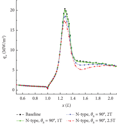
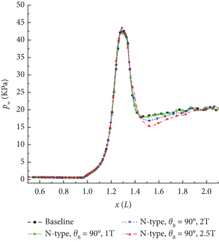

As the magnetic induction intensity increases, the magnetocontrol effect exhibits nonlinear variations. This is due to the fact that the Lorentz force is directly proportional to the square of the magnetic induction intensity.
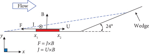
For the compression corner configuration, the flow deceleration can be achieved solely by the addition of a magnetic field, as shown in Figure 13. The interaction between induced current and the magnetic field generates a reverse Lorentz force F.
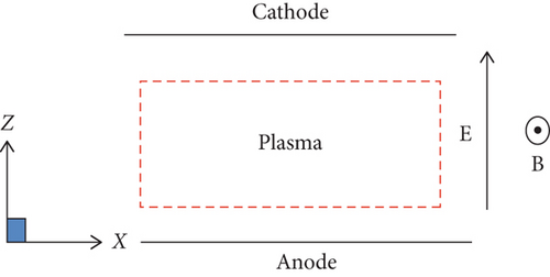
It can be seen from Figure 14 that fluid acceleration can be achieved by applying an electric field E in the direction perpendicular to the x-y plane to counteract the induced current produced by the magnetic field alone and change the direction of the total current, resulting in a Lorentz force that accelerates the fluid.
- 1.
For the magnetocontrol deceleration scheme of compressible corner flow, under the influence of an additional magnetic field, the control area is only affected by the reverse Lorentz force in the deceleration direction, reducing the momentum of the near-wall fluid and thus reducing the boundary layer’s ability to resist separation.
- 2.
For the magnetocontrol acceleration scheme of compressible corner flow, under the influence of both external electric and magnetic fields, the Lorentz force in the control area plays an accelerating role. The velocity profiles near the wall become fuller, enhancing the boundary layer’s resistance to separation. In addition, the Joule heating effect weakens the boundary layer separation control effect of the accelerating Lorentz force.
The study also explored the impact of different external electric field intensities. The results indicated that as the external electric field loading coefficient (used to characterize the electric field’s strength) increases, the separation zone size decreases. When the external magnetic field strength and loading coefficient are sufficiently large (in this study, B = 3 T), it is possible to eliminate laminar boundary layer separation and maintain attached flow.
The study also analyzed the velocity and temperature distributions at the same location, as Figure 15 demonstrates:
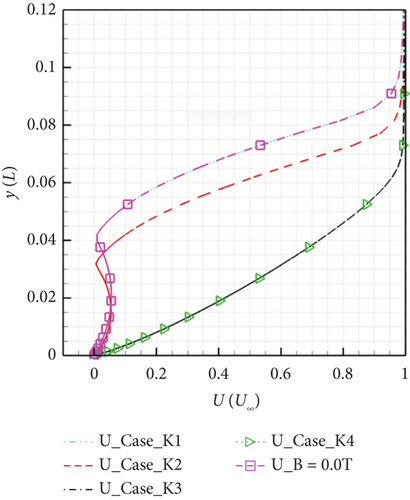
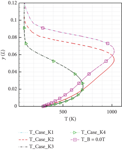
Applying downstream Lorentz force significantly accelerates the boundary layer, resulting in a more robust velocity profile near the wall. Simultaneously, different electric field intensities have a substantial impact on the cross-sectional temperature distribution. When the loading coefficient is large, the separation bubble disappears, leading to a sharp decline in temperature within the cross-sectional boundary layer.
4.2. Influence of External Electromagnetic Field Direction
Jiang et al. [11], using a 30° cylindrical skirt configuration with a magnetic field intensity (B) of 2.5 T, simulated the conditions of high-altitude free-stream flow at H = 56 km. Figure 16 illustrates the surface parameter distribution under different magnetic control directions (0°, 30°, 60°, 90°, and 120°).
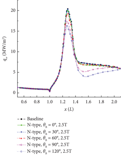
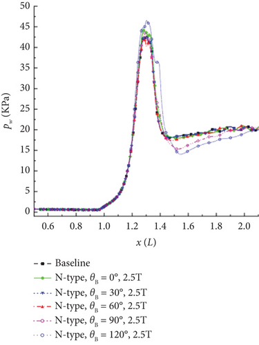
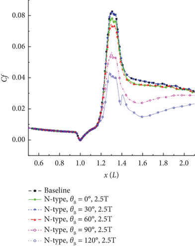
When the local magnetic field is applied perpendicular to the surface, that is, in the 120° direction, it generates the maximum component of Lorentz force in the opposite direction, resulting in the most effective control. At B = 2.5 T, the peak heat flux is reduced by approximately 20%, and the peak friction is reduced by about 48%.
4.3. Influence of Electromagnetic Interaction Location
In a comparative study of the magnetic control results for different positions of external electric and magnetic fields on compression corner plates and inclined wedges, research by Luo et al. [118] indicates that when the electromagnetic interaction region is located in the flat-plate section, the closer the action area is to the downstream, the smaller the pressure plateau area, the higher the plateau pressure, and the smaller the separation region. This is because the separation point gradually moves downstream, and the change in the reattachment point is not significant. The local control area experiences a significant increase in heat flux. When the electromagnetic interaction region is located in the inclined wedge section, the closer the electromagnetic interaction region is to the downstream of the flow field, the larger the range of the pressure plateau area, the higher the plateau pressure, and the larger the separation region. This is because the separation point and reattachment point of the boundary layer gradually return to the uncontrolled separation point position. Therefore, for magnetic control acceleration in compressible corner flow, the closer the electromagnetic interaction location is to the separation region, the better the flow control effect.
As can be seen in Figure 17, Jiang et al. [11] defined three types of magnetic control for high-enthalpy shock–boundary layer disturbances in the study, namely: C-type (local magnetic field located at the corner position), N-type (local magnetic field located at the neck position of the flow structure), and R-type (local magnetic field located at the recompression shock layer position).
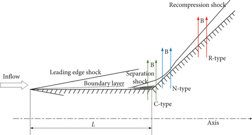
The results indicate that the N-type magnetic control yields the best results. The C-type has less significant control due to lower ionization levels in the separation region flow field. The R-type has almost no effect on the peak heat flux, wall pressure, and friction at the upstream “neck” position, but wall parameters at the control location experience a significant jump.
Gao et al. [132] conducted a study on the variation in magnetic control effects by changing the distance between the center point of the EMFC region and the wall (0.5, 1.0, and 2.0 mm, respectively) when the EMFC region is entirely within the separation region. The results are represented in Figures 18 and 19:
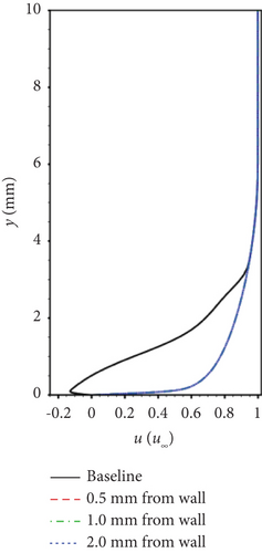
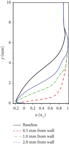
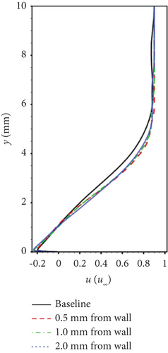
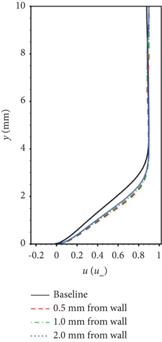
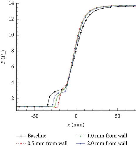
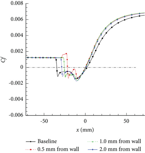
Bringing the EMFC region closer to the wall enhances separation control, indicating that applying Lorentz forces in the reverse low-velocity region at the bottom of the separation region yields the best results.
4.4. Influence of Joule Heating
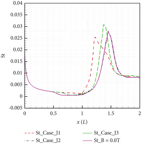
Luo et al. [118] employed a perfect gas model to investigate three sets of compression corner cases (as depicted in Figure 20): considering only the Lorentz force term (Case_J1), considering only the Joule heating–related term (Case_J2), and considering the combined effect of Lorentz force and Joule heating (Case_J3). The results of these cases indicate that when Joule heating is not considered, applying control leads to the acceleration of the boundary layer by the downstream Lorentz force, nearly eliminating the pressure plateau region, but increasing the wall friction coefficient in the original separation region. Calculations from Case_J3 reveal that accounting for Joule heating increases the local static pressure and the electromagnetic flow Joule heating effect weakens the separation control effect of the accelerating Lorentz force. This conclusion aligns with the experimental results of Saito et al. [138].
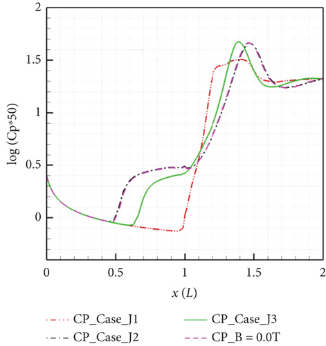
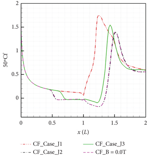
The original expression for the magnetic interaction parameter is S = σB2L/ρ∞u∞, representing the ratio of Lorentz force to inertia force, which has been modified by Jiang [132] to define a novel magnetic interaction number for analyzing the effectiveness of separation suppression. Its expression is SΔP = −σEBLBubble/ΔP, defined as the ratio of electromagnetic force to adverse pressure gradient, where ΔP represents the pressure change before and after the interaction and represents the length of the separation region. Among the two components of the local magnetic interaction number, namely, the adverse local magnetic interaction number and the normal local magnetic interaction number, the adverse local magnetic interaction number is the determining factor in assessing the effectiveness of magnetic control. According to this definition, Joule heating counteracts the weakening of separation caused by the Lorentz force. Therefore, in the design process of EMFC thrusters, the Lorentz force must be sufficiently strong to counteract the thickening of the boundary layer caused by Joule heating. This can be achieved by improving the discharge model for simulation to assist in determining the maximum heat input.
5. Experimental Research on EMFC
- 1.
Difficulties in replicating phenomena: High-temperature effects cannot be accurately replicated using conventional “cold” high-speed ground-based equipment. Furthermore, beyond conventional aerodynamic/thermodynamic phenomena/observations [139] (viscous interactions, thin shock layers, high-entropy layers, real gas properties under flight conditions [140], inflow velocity/enthalpy [141], dual-scale parameters ρL, etc.), the additional electro- and magnetodynamic characteristics of flow interactions lead to “magnetized plasma aerodynamics” at high speeds, which continuous facilities struggle to emulate. Therefore, a single high-speed testing facility cannot simulate an entire flight envelope, necessitating the development of diverse high-speed testing facilities [142]. The typical approach is a partial simulation. In this approach, in the low-speed region with Mach numbers between 5 and 12, the free-stream temperature is reduced to reduce the speed of sound, thereby increasing the Mach number of the free-stream flow to simulate high-speed conditions. At speeds exceeding 3–4 km/s (hypervelocity), air undergoes chemical reactions that simulate the velocity, pressure, and temperature of real gases under flight conditions. At altitudes above 80 km and below 130 km, the rarefaction parameter Knudsen number ranges from 0.01 to 10. Parameters such as the Knudsen number, Mach number, surface-averaged temperature, and stagnation temperature ratio are simulated.
- 2.
Limited model size: The influence of EMFC effects depends on the size of the interaction region in which these effects occur. In experiments, models are typically one to two orders of magnitude smaller than real hypersonic aircraft, rendering finite-rate kinetics significant, even if they would be irrelevant under actual flight conditions.
- 3.
To prevent quenching, conventional superconducting magnets, such as neodymium-iron-boron (NdFeB) permanent magnets, are unable to meet the rapid dynamic field strength variations required for high-speed EMFC, which range from 0 to 2 T/s. Furthermore, their magnetic field strength is reduced as temperature increases, which limits their application. High-temperature superconductors (HTSs), characterized by higher critical temperatures, have been developed to address this issue, as they are less prone to quenching and can achieve higher ramping rates. In 2022, a ramping rate of 272 T/s was achieved with 0.5 T of rare-earth barium copper oxide (ReBCO) HTS [143], with a total superconducting mass of only 696.5 g. This study demonstrated that it is feasible to upgrade magnets to produce higher magnetic field strengths (2 T and above). However, the risk of losing superconducting properties at field strengths exceeding the critical level remains, necessitating stringent control over current and temperature. Plasma and magnetic fields can be generated by combining pulsed DC discharges with permanent magnets, rather than relying solely on DC power supplies and superconducting magnets [144].
Current experimental research directions in EMFC primarily include drag reduction in aircraft, reduction of losses in turbomachinery compressors, aircraft noise reduction, surface friction reduction [145], enhanced jet mixing, MHD generators [146], plasma effects on shock waves in hypersonic flows [147–149], plasma-assisted ignition in high-speed flows, and magnetic fluid control in boundary layers [150, 151]. Additional topics are transition control, reduction of turbulent boundary layer thickness, mitigation of adverse effects of shock–boundary layer interactions, hypersonic aircraft power generation, and magnetic control of the delayed wing-leading-edge separation-induced dynamic stall typically observed in subsonic applications [151].
- 1.
Common ground-based wind tunnel test facilities utilized for EMFC, including arc wind tunnels, plasma wind tunnels, low-temperature wind tunnels, and shock tunnels.
- 2.
Given the significance of EMFC in high-speed flight with its contributions to long duration, high dynamic pressure, and medium-to-large hypersonic wind tunnels, this paper also distills and summarizes research results related to two commonly employed methods for enhancing the efficiency of EMFC experimental facilities: (1) power extraction and (2) studies related to enhanced electrical conductivity.
- 3.
Additionally, the paper provides a comprehensive summary of the current applications of EMFC in experimental settings. This includes EMFC acceleration techniques, EMFC shock wave modulation, EMFC thermal protection techniques, EMFC drag reduction methods, and EMFC boundary layer techniques. The paper places particular emphasis on research related to MHD boundary layer control.
The following presents the specific research content.
5.1. Ground Experimental Equipment
The following subsections describe the characteristics of various types of wind tunnels, representative wind tunnel facilities, testing capabilities, and related research.
5.1.1. Arc Wind Tunnels
Arc wind tunnels such as NASA’s AHSTF [152] offer test durations of up to several tens of seconds. Wind tunnel simulations can achieve a total enthalpy of up to 100 MJ/kg, generating a test flow with relatively high ionization and noticeable EMFC effects. As a result of these characteristics, the spatial magnetic field not only affects the high-temperature conductive airflow downstream of the shock but also influences the charged particles ahead of the shock. This introduces some differences compared to real flight conditions. Additionally, as a result of structural strength limitations, the total temperature and pressure capabilities of such wind tunnels are insufficient. Furthermore, there are contamination components in the test medium, rendering it impossible to simulate conditions for supersonic combustion (Ma ≥ 8). Furthermore, long-duration down-blow transient-type equipment such as wind tunnels commonly faces significant challenges in terms of thermal protection.
5.1.2. Plasma Wind Tunnels
Bityurin [153] studied the effects of EMFC phenomena using Russia’s large-scale high-frequency plasma (HFP) wind tunnel. Their research findings indicated that Lorentz body force effects could alter turbulent structures, suppress flow separation, redistribute pressure and heat flux on an aircraft’s surface, optimize the operational efficiency of scramjet/ramjet engines, control ignition, improve combustion in scramjet engine combustion chambers, and generate onboard power and control boundary layers. However, an HFP wind tunnel requires a substantial amount of energy to generate high-density plasma (200 kW).
To provide higher energy, Macheret [122] from Princeton University conducted theoretical and experimental research on EMFC boundary layer acceleration using sliding arc discharges. Their results demonstrated that the magnetic field could accelerate the plasma columns, affecting the flow near the wall and accelerating and controlling the boundary layer flow. Unfortunately, their research used DC power sources and could not provide sufficient high-frequency power for experiments involving oblique shock wave control.
5.1.3. Cryogenic Wind Tunnels
Changbing et al. [144] conducted experimental research on EMFC around oblique shocks in a cryogenic wind tunnel. The objective of their experiments was to weaken the intensity of oblique shocks by utilizing MHD interactions and altering the boundary flow characteristics around the slope. Pulsed DC discharges were employed to generate high-density plasma columns, and the magnetic sources were neodymium—NdFeB rare-earth permanent magnets. The Lorentz body force effects on plasma-induced airflow velocities were validated through particle image velocimetry (PIV) measurements. The experimental results revealed that plasma could impact neutral gas molecules, transferring momentum and accelerating the flow around the slope. Consequently, the plasma columns exhibited significantly higher velocities in the presence of a magnetic field compared to the case when no magnetic field was applied. Under the influence of Lorentz body forces, the oblique shock in front of the slope moved upstream. The flow field characteristics were examined by varying four parameters, namely, the magnetic field direction, distance between electrodes, slope angle, and pulsed DC electric intensity. The graphical results in Figure 21 confirmed that EMFC could substantially alter the flow characteristics around the slope. When the slope angle was 20°, the Pitot pressure ratio after oblique shock decreased by 19.66%.
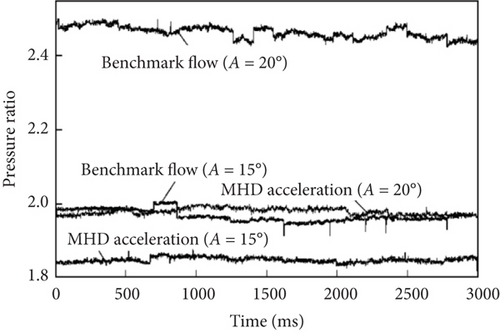
In this study, the influence of EMFC acceleration and deceleration on flow characteristics was measured using Pitot pressure and Schlieren imaging; the results were depicted in Figure 22.
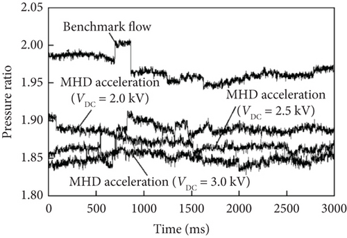
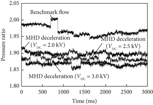
Furthermore, because a cryogenic supersonic wind tunnel can operate stably for more than 10 s, the reliability of the results can be determined.
5.1.4. Shock Wave Wind Tunnels
Shock wave wind tunnels are crucial in the realm of hypersonic aerodynamics based on their high enthalpy, high total temperature, and extended test durations. Wind tunnels are essential tools for conducting aerodynamic and aerothermodynamic research at high Mach numbers. High-enthalpy shock wave wind tunnels can replicate the conditions of highly hypersonic flight environments, facilitating experiments not only in aerodynamics and aerothermodynamics under conditions with elevated real gas effects but also in areas such as ignition in scramjet engines, stage separation, and electromagnetic scattering. Representative high-enthalpy wind tunnel facilities include the LENS wind tunnel in the United States [139, 154], HYPULSE wind tunnel [155], Caltech’s T5 wind tunnel [141], Oxford University’s T6 [156, 157], University of Queensland’s T4 [158, 159] and X3 [160], Marseille University’s TCM2 [161], DLR’s HEG [162], HIEST wind tunnel in Japan [163], HEG wind tunnel in Germany, and China’s detonation-driven high-enthalpy shock wave wind tunnels JF-10, JF-12 [164–166], FD-21 [166, 167], and newly established JF-22. High-enthalpy shock wave wind tunnels require relatively low investment, operate with air as the test gas, achieve extremely high levels of simulated flow enthalpy and total pressure (expansion tube facilities can reach enthalpies of up to 100 MJ/kg and total pressures in the gigapascal range), and have relatively low operational costs, rendering thermal protection concerns almost negligible. These facilities have been extensively utilized in foreign research on scramjet/ramjet engines. High-enthalpy shock wave wind tunnels are transient wind tunnels capable of generating extremely high temperatures and pressures. Although their effective test durations are limited to milliseconds, the successful application of advanced testing instruments has enabled the study of the complex gas dynamics, aerodynamic optics, and aerodynamic acoustics of aircraft operating at high hypersonic speeds within this brief window [140]. The low free-stream ionization level in high-enthalpy shock wave wind tunnels is similar to that in the magnetic control environments experienced during actual flight. However, this low-ionization level imposes higher demands on the simulation speed and magnetic field strength of equipment.
For high-enthalpy shock wave wind tunnels, Shen et al. [168] systematically introduced tunnel drive technology [141], flow field detection technology, standard testing technology, and specialized test technologies such as supercombustion ramjet engine testing technology, stage separation testing technology, and electromagnetic scattering testing technology. To achieve enhanced drive efficiency, high-performance drive technology typically combines variable cross-section driving with the heating of lightweight gases. Determining free-stream parameters requires a combination of traditional measurement methods and the development of optical testing technologies integrated with computational fluid dynamics. Flow field diagnostic technologies primarily include planar laser–induced fluorescence, tunable diode laser absorption spectroscopy, and coherent anti-Stokes Raman spectroscopy.
The main steps for determining the free-stream parameters in high-enthalpy shock wave wind tunnels are presented in Figure 23.

In high-enthalpy shock wave wind tunnels, when the driving gas passes through the bifurcation region formed near the wall by an incident shock wave, early contamination of the test gas can occur, as shown in Figure 24. Therefore, it is necessary to develop techniques to delay the contamination of test gases.
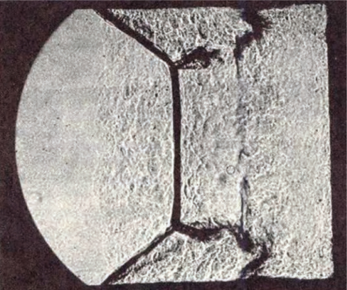
The California Institute of Technology’s T5 wind tunnel added a sleeve at the end of the shock tube and testing results indicated that this sleeve effectively slowed the early contamination of the driving gas [170].
Lu et al. [171] summarized the experimental capabilities of free-piston high-enthalpy pulse wind tunnels, including free-stream parameter calibration techniques, aerothermal and pressure measurements, aerodynamic force measurements, scramjet engine testing technology, hypersonic boundary layer transition, free-flight experiments, aerodynamic optics research, electromagnetic radiation technology research, and flow field diagnostics using spectral techniques. Table 3 summarizes the equipment parameters of major high-enthalpy shock wave wind tunnels worldwide.
| Wind tunnel | Affiliation | Driver technique | Diver tube | Driver tube | Nozzle exit diameter/m | Vmax /(km/s) | Masimulated | tef/ms | hmax/(MJ/kg) | ||
|---|---|---|---|---|---|---|---|---|---|---|---|
| L/m | D/m | L/m | D/m | ||||||||
| T4 | UQ | Free-piston | 26 | 0.229 | 10 | 0.076 | 0.388 | ~5.5 | 4~10 | ≥ 1 | 15 |
| T5 | Caltech | 30 | 0.3 | 12 | 0.09 | 0.314 | ~6.3 | 4~7 | ≥ 1 | 20 | |
| HIEST | JAXA | 42 | 0.6 | 17 | 0.15 | 0.88 | ~7 | 8~16 | ≥ 2 | 25 | |
| HEG | DLR | 33 | 0.55 | 17 | 0.15 | 1.2 | ~7 | 6~10 | 1~6 | 25 | |
| FD-21 | CAAA | 75 | 0.668 | 34 | 0.29 | 1.2/2.0 | ~7 | 10~16 | 2~10 | 25 | |
| LENSI | GASL | Heated light gas | 7.62 | 0.28 | 18.3 | 0.203 | 1.5 | ~4.6 | 6~22 | 5~18 | 10 |
| LENSII | 18.3 | 0.61 | 30.5 | 0.61 | 1.8 | ~2.7 | 3 ~ 10 | 30~100 | 4 | ||
| JF-12 | IMCAS | Detonation | 99 | 0.4 | 89 | 0.72 | 2.5 | ~3 | 5~9 | ~100 | 3.5 |
Udagawa et al. [172] conducted experimental research on EMFC using a shock wave wind tunnel with a testing duration of approximately 1 ms. The results indicated that EMFC effect can alter the upstream boundary layer flow and impact the oblique shock wave ahead. Wu et al. [173] studied the effects of electrohydrodynamics (EHD) in shock tubes considering electric field forces, but not magnetic field forces. Han et al. [174] conducted experimental research on EMFC effects on the flow around a cylinder in a shock wave wind tunnel.
5.2. Experimental Techniques to Improve EMFC Efficiency
The main advantages of using EMFC are that it does not require any mechanical moving parts, can be rapidly initiated, operates at high response frequencies, and minimizes flow resistance. However, some disadvantages are also apparent, including the requirement for conducting currents and high power. To address this issue, it is essential to develop power extraction technologies and enhance fluid conductivity.
5.2.1. Power Extraction
To satisfy increasing power demands, power extraction technologies can be developed by utilizing MHD generators to extract surface energy. This approach can provide electrical power for hypersonic flights and enable energy redistribution through direct MHD interactions by extracting power from the surrounding airflow [75].
Bityurin [153] conducted experiments in his MHD research to maximize power extraction using pulsed DC discharges to generate high-density plasmas and reduce energy consumption based on voltage–current curves. The results indicated that the extracted power level was a small percentage of the total enthalpy flux. Additionally, proximity to electrodes may play a dominant role in power extraction levels. It is noteworthy that the Hall effect has a significant impact and places higher demands on MHD generator configurations.
The reason for employing pulsed DC discharges is that as the pressure increases, DC discharges are less prone to diffusion and high-voltage pulsed discharges can withstand higher applied electric fields [175], making them more efficient for ionization compared to stable DC discharges with the same potential difference. This characteristic facilitates greater power transmission during the pulse, thereby increasing the conductivity. Additionally, DC power sources ensure the continuity of applied Lorentz forces [176].
5.2.2. Enhancing Conductivity
There are three main ways to increase gas conductivity.
Development of ionized gas technology: Thermal ionization, although being replaced gradually as a result of higher power demands compared to low-temperature plasmas, can still be induced through methods such as high-voltage electric fields, laser beams, directed microwaves, and radiation sources [125, 126].
The development of discharge technology has led to two common types: glow discharge [125, 126] and DBD, both exhibiting similar physical properties. DBD is a self-limiting plasma discharge that requires high power and can sustain continuous discharge at atmospheric pressure. To maximize the efficiency of high-speed flow control, the gap between the anode and cathode regions is extremely small, and they are separated by a very thin dielectric layer. Some studies have attempted to improve DBD efficiency by limiting electrostatic shielding. However, overall, DBD is not practical for high-speed flow control. Compared to DBD, most glow discharge studies have been conducted at relatively low pressures with wider gaps between the anode and cathode regions, which are more suitable for high-speed flow environments. The effect of glow discharge mainly originates from the Joule heating effect, which can change the local Mach number, reduce local sound speed, and affect the geometry of resistance and shock waves [177].
Increasing magnetic field strength: Electromagnetic actuators can be installed in flat plates or airfoils, but power consumption and encapsulation are two critical issues that must be addressed, necessitating the careful selection of magnets. Compared to electromagnets, permanent magnets do not consume power, have higher strength, and are lighter. Rare-earth permanent magnets are suitable for placement on thin control surfaces [178]. However, they have notable drawbacks. The high-temperature aerodynamic environments experienced during hypersonic flight significantly weakens magnetic field strength at the surface of permanent magnets and even cause demagnetization at the Curie point [179]. Even with complex active cooling systems, the use of permanent magnets in high-temperature environments remains challenging. The neodymium magnets can only operate below 400 K, whereas some samarium–cobalt alloy magnets can be used at temperatures above 800 K, rendering them more suitable for high-temperature and high-speed environments. However, they produce a smaller overall magnetic field strength than neodymium magnets [180]. Therefore, magnet development should focus on broadening operating temperature ranges. Currently, as a result of temperature limitations, permanent magnets can only be used on slender control surfaces of hypersonic aircraft to a certain extent. Second, regardless of whether samarium–cobalt alloy magnets or neodymium magnets are used, their maximum surface magnetic field strengths do not exceed 0.5 T.
5.3. EMFC Experiments in Various Applications
Some representative experimental studies on EMFC in various applications are listed in Table 4.
| Year and author | Key contributions | |
|---|---|---|
| Magnetic field-assisted thrust enhancement | Takai (2012) [181] | Influence of electrode cross-sectional shape on thrust efficiency |
| Nishihara (2006) [182] | Magnetic flow acceleration/deceleration (magnetic field 2 T, Mach number 3–4); effects of Lorentz force and Joule heating | |
| Li (2011) [183] | Flow acceleration/deceleration through nonequilibrium ionized MHD flow control | |
| Magnetic control at inlet oblique shocks | Bobashev (2000) [184] | Early experiments on MHD inlet shock control in shock wave wind tunnels |
| Lineberry (2004) [185] | Control effects on three basic two-dimensional wedge structures with orthogonal magnetic field and velocity vector | |
| Macheret (2001) [124] | Selection of magnetic interaction parameters at nondesign Mach numbers to increase air capture and reduce total pressure loss | |
| Shneider (2003) [19] | ||
| Merriman (2001) [186] | Control of oblique shock angle using glow discharge MHD | |
| Li (2019) [183] | Experimental verification of principles for controlling inlet plasma/MHD shock wave systems | |
| Achieving magnetic control for shock detachment and heat reduction | Ziemer and W. B. Bush (1948–1959) [187, 188] | Ma 4.5, hemispherical cylinder, external magnetic field intensity 4 T; 7.5-fold increase in shock detachment distance, reduction in model surface heat flux |
| Baccarella (2011) [189] | Experimental study of magnetic control for conical shock detachment in HEAT and “Scirocco” high-enthalpy arc-heated wind tunnels | |
| Wilkinson (1964) [190], Cambel (1966) [191] (1967) [192] | Heat transfer characteristics of ionized flow under the influence of electromagnetic fields | |
| Ali (2009) [193] | Experimental study of magnetic control surface temperature and heat flux for hemispherical cylinders and cylinders | |
| Li Kai (2017) [91] | First successful demonstration of the effectiveness of magnetic control thermal protection systems under high-temperature air inflow conditions | |
| Unsuccessful attempts at achieving shock detachment and heat reduction through magnetic control | Bityurin (2007) [194] | Strong Hall effect resulting in reduced conductivity, changes in Lorentz force and energy distribution; no observable increase in bow shock detachment distance or significant reduction in heat flux during magnetic control experiments with a cylinder model at TsAGI MHD Wind Tunnel facility |
| Nowak (1973) [195] | Increased heat flux at stagnation point with external magnetic field; unpredictable heat flux distribution changes without external magnetic field but with conductive fluid | |
| Shang (2002) [196] | No detectable changes in shock detachment distance and drag in low-conductivity environment; improved magnetic control effects with increased magnetic field and conductivity; first experimental verification of electrostatic phenomena | |
| Magnetic drag reduction | Benmou (2004) [197] | Experimental research on electromagnetic force-controlled cylinder flow boundary layer drag reduction |
5.3.1. Magnetofluiddynamic Flow Acceleration Technology
MHD accelerators, commonly referred to as cross-field accelerators, generate plasma by applying an external power source to overcome the self-inductive current and reverse its direction. This process generates Lorentz forces in the flow direction that accelerates the fluid. MHD acceleration can be applied in hypersonic propulsion systems, such as MHD-assisted scramjet engines. However, when the acceleration current is applied, the gas temperature and pressure increase significantly, whereas the velocity changes only slightly. This is because the electrical input power must be converted into the kinetic energy and/or enthalpy of the working gas. Therefore, increasing the energy conversion efficiency or gas enthalpy is advantageous for applications in advanced propulsion systems.
To design more efficient operating conditions for pulsed MHD accelerators, Takai et al. [181] conducted principal verification experiments using MHD accelerators and model rocket engines. They studied the influence of the electrode cross-sectional shape on the thrust efficiency by providing preionization through a pulsed discharge to generate stronger Lorentz forces. The experimental setup consisted of a pulsed power supply system, MHD acceleration channel, model rocket engine, permanent magnets, and diagnostic system, as shown in Figure 25.
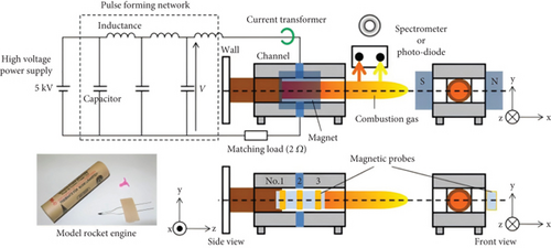
Figure 26 illustrates the linear MHD accelerator employed in this experiment.
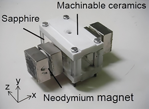
The results indicated that the thrust efficiency of the pulsed MHD accelerator increased as the electrode cross-sectional area decreased. This effect was attributed to a stronger EMFC effect generated with the same current density, resulting in a higher gas velocity and thrust. Conversely, as the electrode area increased, the Joule heating effect dominated, diminishing the contribution of the MHD effect. In such cases, increasing the plasma conductivity and magnetic field strength can further enhance the performance of MHD accelerators.
Nishihara et al. [182] conducted experiments to control airflow acceleration and deceleration under conditions of a magnetic field strength of 2 T and Mach numbers of 3–4. The results showed that the pressure changes were greater during deceleration than during acceleration. This effect was attributed to the Joule heating effect synergistically increasing the pressure during deceleration, whereas it had an opposite effect during acceleration. The magnitude of the pressure increase depended on the polarity of the Lorentz force, indicating that the Mach number and pressure in the test section were influenced by electromagnetic forces, as shown in Figure 27.
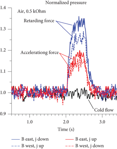
Li et al. [183] conducted experimental research on flow acceleration and deceleration using nonequilibrium ionized EMFC with a capacitively coupled radio frequency discharge. The results indicated that under the influence of acceleration and deceleration Lorentz forces, the static pressure increased and the Mach numbers decreased. The magnitudes of the numerical changes during deceleration were slightly greater than those during acceleration.
5.3.2. Magnetohydrodynamic Shock Wave Control Technology
EMFC technology can control the interaction between oblique shock waves and the lip of an inlet. This technique involves altering the position of shock waves in the inlet under off-design Mach numbers using EMFC. It generates large-volume plasma using balanced or unbalanced ionization techniques. By applying an external load to produce directional currents and utilizing the Lorentz force within the magnetic field, the airflow is accelerated or decelerated, thereby redirecting the shock waves at the inlet to interact with the lip, as depicted in Figure 28.
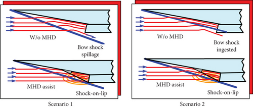
Researchers at the Russian Institute of Physics, led by Bobashev et al. [184], were among the first to conduct experiments on the EMFC inlet shock wave in shock tunnels. They used rare gas krypton with a relatively long electron–ion recombination time as the test medium. The test conditions included a supersonic total temperature of 9800 K and theoretical electrical conductivity of 3200 S/m. This experiment initially demonstrated the feasibility of using a magnetic fluid to control oblique shock waves in the inlets. However, achieving equilibrium ionization at the required temperatures for realistic flight environments requires the Mach numbers to exceed 12. Even with artificially introduced seed ions, Mach numbers of 8 or higher are required for equilibrium ionization to occur. Therefore, subsequent research on MHD flow control in inlets primarily employed nonequilibrium ionization techniques, such as gas discharge.
Macheret et al. [18] and Shneider et al. [19] proposed a method for EMFC inlet shock wave by injecting high-energy electron beams along the magnetic field lines into the channel. This method achieved EMFC inlet shock waves at off-design Mach numbers. This study involved both a theoretical analysis and experimental research on the control effectiveness of the nonviscous MHD model based on electron beam ionization, as depicted in Figure 29, at off-design Mach numbers.
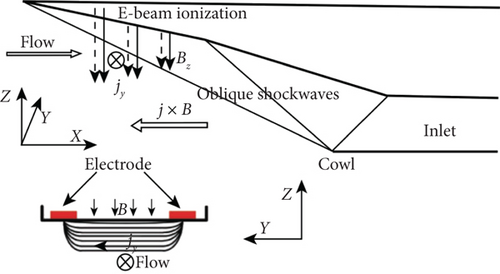
The results showed that when Ma > Mad, reasonable control parameters could increase air capture and reduce the total pressure losses. However, for Ma < Mad, Joule heating led to reduced air capture and increased total pressure loss.
Lineberry and Bityurin [185] simplified the inlet configuration to wedge-shaped structures and conducted experiments on the control effects of magnetic fields and velocity vectors orthogonal to three basic two-dimensional wedge structures. These three two-dimensional wedge structures were as follows: Type I with symmetrical single-angle wedges featuring surfaces made of metal or ceramics, Type II with double-angle wedges, and Type III with single-angle wedges with relatively symmetrical shield plates. Type I was the first model structure used. Type II was used to simulate double-slope inlets, whereas Type III was based on the first two types and aimed to simulate the lip effects of typical inlet structures. This usage was intended to demonstrate the ability of EMFC to change the shock wave angle. The experimental setup for Type III is shown in Figure 30. Compared to Type I single-angle wedge structures, Type III wedge models had two changes: (1) extending a certain distance downstream to prevent wake-induced separation and (2) installing a plate parallel to the inflow direction above the wedge, positioning based on experimental results to simulate the lip effects of typical inlet structures.
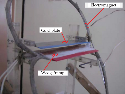
Table 5 provides a chronological summary of the experimental studies based on the aforementioned three wedge models.
| Test | Date | Model (see note) | Magnet | Visualization | Comment |
|---|---|---|---|---|---|
| 117 | 07/16/02 | Type I—Copper | Eight turn—Double oval | High-speed photography | Successful |
| 118 | 10/15/02 | Type I—Copper | Eight turn—Double oval | High-speed photography | Model damaged |
| 131 | 04/24/03 | Type I—Ceramic | Eight turn—Double oval | High-speed photography digital camera | Full view potential measurement |
| 132 | 05/28/03 | Type I—Ceramic | Eight turn—Double oval | High-speed photography digital camera | Full view filter NC-9 potential measurement |
| 133 | 05/28/03 | Type I—Ceramic | Eight turn—double oval | High-speed photography digital camera | Full view filter NC-9 potential measurement |
| 134 | 05/28/03 | Type I—Ceramic | Eight turn—Double oval | High-speed photography digital camera | Full view filter for oxygen line potential measurement |
| 135 | 05/29/03 | Type I—Ceramic | Eight turn—Double oval | High-speed photography digital camera | Full view filter for oxygen line potential measurement |
| 136 | 05/29/03 | Type II—Ceramic double wedge | Six turn—Double oval | High-speed photography digital camera | Full view filter for oxygen line potential measurement |
| 137 | 07/22/03 | Type III—Ceramic wedge with opposing cowl plate | Eight turn—Double oval | High-speed photography digital camera | Full view filter for oxygen line potential measurement |
| 138 | 07/22/03 | Type III—Ceramic wedge with opposing cowl plate | Eight turn—Double oval | High-speed photography digital camera | Full view filter for oxygen line potential measurement |
- Note: (1) Type I: symmetrical single-angle wedge, metal or ceramic surfaces; (2) Type II: double-angle wedge; and (3) Type III: single-angle wedge with an opposing cowl plate.
Experiments were conducted in a high-speed wind tunnel driven by an MHD accelerator. Figure 31 shows the bottom of the device and test section [153]. The wedge models were designed with embedded electromagnetic coils and surface electrodes to observe the disturbance of flow structures around the wedge, which was caused by magnetic fluid interactions, and to measure the electromagnetic force induction.

Figure 32 illustrates the numerical simulations and experimental results of the flow field with and without the MHD effects for the Type III model. The upper part of the figure shows the supersonic flow unaffected by the MHD interactions, whereas the lower part shows the subsonic flow influenced by the MHD interactions.
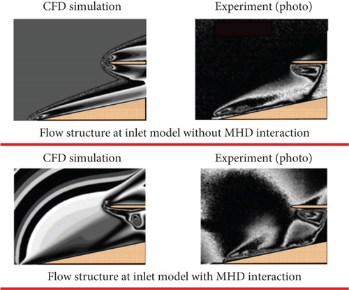
The experimental results confirmed that MHD interactions significantly affected the flow structures around the wedge, causing a significant change in the oblique shock wave angle. When operating under off-design conditions, the MHD interactions can be used to adjust the position of the oblique shock wave to interact with the lip. With the addition of an external magnetic field, the main oblique shock wave under the inlet moves upward to interact with the lip under the design conditions. Additionally, in regions with stronger magnetic field intensity, secondary oblique shock waves are formed near the upstream edge.
Merriman et al. [186] placed a diffusion plasma source at the tip of a wedge and conducted glow-discharge EMFC experiments using a mixed flow of nitrogen and helium with a Mach number of 2. The results showed a significant change in the oblique shock wave angle, and because of the plasma heating characteristics, the Mach number decreased from 2 to 1.8. Based on this plasma source design concept, Gnemmi et al. [198] placed a plasma source at the cone tip of the aircraft for discharge experiments, raising free-stream conditions to a Mach number of 4.57 and a static pressure of 54 kPa, achieving favorable results.
Falempin et al. [199], in collaboration with the European Missile Group, conducted an experimental study on flow control in the inlet of supersonic air ducts using surface plasma aerodynamic excitation. Li et al. [9] provided a review of their work. The experiments were conducted in the T-313 supersonic wind tunnel in the UK, using a Mach 2.0 inlet model. The flow control effects were investigated under Mach numbers 2.5 and 3.0, with an excitation power of 6.5 kW. Figure 33 shows Schlieren images of the shock wave structures with and without plasma excitation.
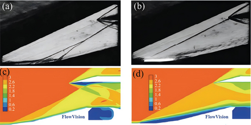
The principle verification experiments successfully demonstrated plane-induced oblique shock waves, forward movement of oblique shock wave positions, and flow separation control at the rear wall step and cavity using plasma aerodynamic excitation.
Macheret et al. [125, 126] introduced the concept of a virtual inlet cowl based on the heating performance of the plasma. It was shown that plasma heating can alter the upstream flow field to reduce lip spillage in the inlet design. However, this requires a considerable amount of power and can only be used during the acceleration process to reach the design Mach number typically in a short duration, as confirmed by preliminary experiments conducted by McAndrew et al. [200].
5.3.3. Magnetofluiddynamic Thermal Protection Technology
The velocities of space reentry vehicles and planetary explorers returning to Earth can exceed 6 km/s. At these simulated speeds, the heat flux exceeds 300 MW/m2 [141]. Sustaining continuous equipment operation under such conditions poses a significant challenge, and high-temperature effects cannot be replicated in conventional “cold-state” hypersonic ground equipment. In a hypersonic low-pressure airflow (M > 10), the conductivity behind the bow shock waves may be sufficient to generate strong magnetofluiddynamic interactions under the influence of magnetic fields on the order of 1 T. Therefore, electromagnetic interactions are highly suitable for controlling the shock wave standoff distances and reducing the surface heat flux [201–203].
Table 6 provides an overview of the research on shock wave standoff distance control in high-enthalpy aerodynamic facilities using EMFC models.
| Year | Facility | Test conditions | Test gas | Type of magnet | Research contents |
|---|---|---|---|---|---|
| 1959 | Electromagnetic shock tube |
|
Air | Electromagnet 4 T | Shock standoff |
| 2004 | Arc-jet wind tunnel |
|
Ar | Neodymium 0.36 T | Shock standoff |
| 2008 | Expansion tube |
|
Air N2 | Neodymium-iron-boron 0.65 T | Shock standoff surface pressure |
| 2009 | L2K arc wind tunnel |
|
Ar | Electromagnet 2.8 T |
|
| 2012 | SCIROCCO plasma wind tunnel | Ma: 10 | Air | Electromagnet 0.8 T |
|
| 2012 | Arc-jet wind tunnel |
|
Ar | Neodymium 0.4 T | Heat flux |
| 2017 | Plasma wind tunnel |
|
Air | Electromagnet, N52SHT 0.75 T |
|
| 2017 | HEG shock tunnel |
|
Air | Pulse magnet 4.5 T | Shock standoff |
| 2019 2020 | X2/X3 expansion tunnel |
|
Ar | NdFeB~0.8 T | Drag force shock standoff |
The theoretical research model for the MHD interactions is depicted in Figure 34, which illustrates the formation of a shock layer after a shock wave. Its flow characteristics can be roughly estimated using shock wave relations.
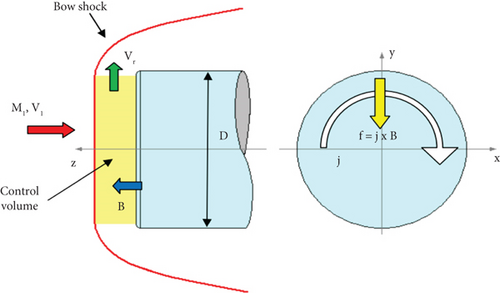
Regarding the primary mechanisms of magnetofluiddynamic shock wave control, some early studies believed that magnetofluiddynamic effects were the primary cause [205, 206]. However, it is widely accepted that plasma heating is the predominant factor [207]. This conclusion was validated using calculations conducted by Poggie [208].
There are two types of experimental conclusions in the field of EMFC shock wave standoff distance and heat reduction. The first type consists of “conventional” experimental conclusions that validate existing theories, while the second type comprises “unconventional” experimental conclusions where experimental results deviate from conventional theoretical results.
5.3.3.1. Conventional Findings: Magnetofluiddynamic Thermal Control Achievements
Through the application of a magnetic field to generate Lorentz forces, the shock wave standoff distance can be increased for thermal protection. This concept was initially proposed by Ziemer and Bush [187, 188]. They conducted calculations and experiments to study the influence of an applied magnetic field on the shock wave standoff distance in ionized air, where ionized air flowed at Ma 4.5, through a hemispherical cylinder positioned within a shock tube. The results revealed a substantial increase in the shock wave standoff distance by a factor of 7.5 when a pulsed current of 4-T external magnetic induction field was generated near the stagnation point in the coaxial coil. In addition, the surface heat flux of the model decreased. Figure 35 presents representative experimental observations of the standoff distance in magnetically controlled shock waves.
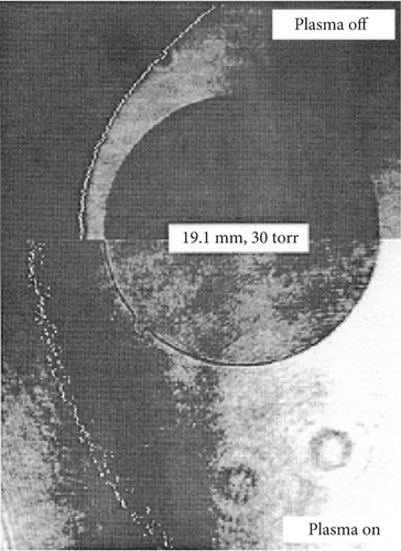
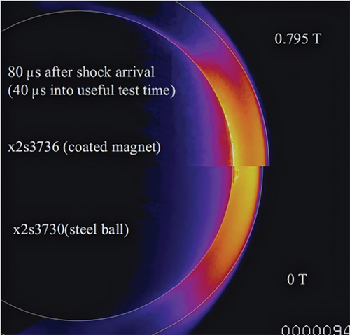
Baccarella et al. [189] conducted experimental research on magnetic control shock wave standoff distances in two high-enthalpy arc-heated wind tunnels, HEAT and “Scirocco.” The experimental model used the conical body model shown in Figure 36.
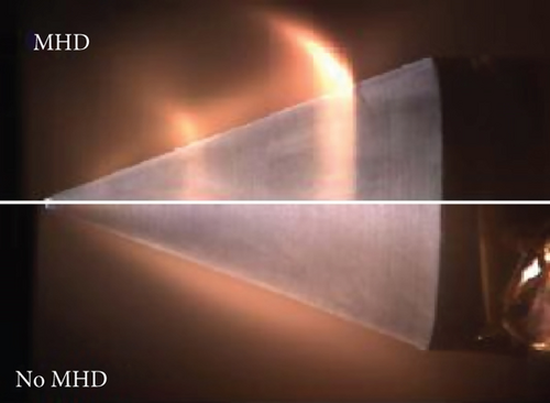
Wilkinson [190] studied the heat transfer characteristics of ionized flows under the influence of electromagnetic fields by analyzing the changes in the stagnation point heat flux of blunt cones. This experiment employed thermocouples to measure heat flux and permanent magnets to enhance the applied magnetic induction field. With the increase in magnetic induction intensity (squared), the stagnation heat flux decreased by nearly 30%. However, owing to the short operating time of thermocouples, the magnetic induction polarity caused discrete electromotive forces, resulting in pseudotemperature readings, thus compromising the accuracy of the heat flow measurements. Furthermore, this study suggests the importance of considering transport characteristics as essential similarity parameters for magnetic interactions.
In the late 1960s, Cambel et al. [191, 192] conducted a series of experiments on magnetofluiddynamics and aerodynamics, including heat transfer studies. Li et al. [92] conducted fundamental experimental research on magnetically controlled thermal protection in high-temperature thermochemical nonequilibrium flow fields. Boron nitride was chosen as the ceramic outer shell material, and permanent magnets were utilized to generate a magnetic field in conjunction with water cooling. This experiment marked the pioneering international demonstration of the effectiveness of magnetically controlled thermal protection systems under high-temperature air inflow conditions.
Ali [193] conducted experimental research on reducing the heat flux in high-enthalpy ionized argon flows using an externally applied magnetic induction field in the L2K arc-heated wind tunnel. The test models were axisymmetric blunt-body models with integrated magnetic coils named C2 and C3, where C2 was a hemispherical cylinder, and C3 was a similarly sized cylinder, as shown in Figure 37. An electromagnetic field is generated by the coils within the models.
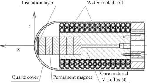
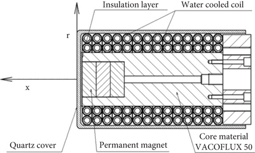
The main flow parameters of the tests are listed in Table 7.
| Parameters | Values |
|---|---|
| Gas mass flow rate, kg/s | 0.020 ± 0.0002 |
| Reservoir pressure, kPa | 37.5 ± 0.75 |
| Specific enthalpy, MJ/kg | 2.02 ± 0.12 |
| Total temperature, K | 3886 ± 224 |
The change in the flow field was monitored by light emitted from argon-excited atoms or ions, and the magnetic control effect of the C3 model is shown in Figure 38.
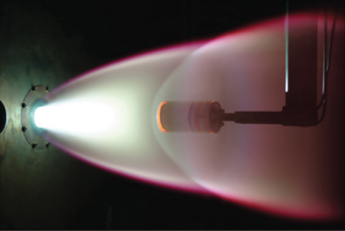

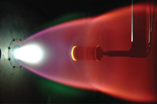

After applying the magnetic induction field, the colors of the airflow changed significantly before and after the shock waves, and a bright green spot was observed in the stagnation region. However, the shock wave standoff distance changed minimally, with only slight variations in the shock wave curvature near the central axis.
Figures 39 and 40 are the IR images of the surfaces of the C2 and C3 models with and without an externally applied magnetic induction field, obtained using the IR thermophotometer method.
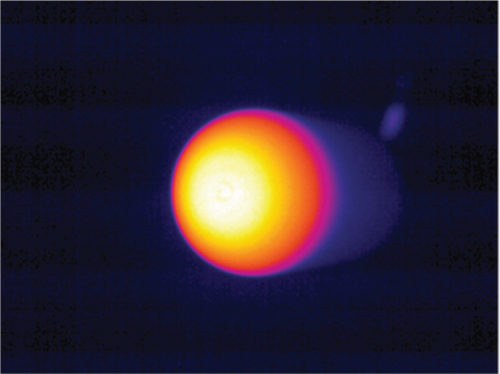
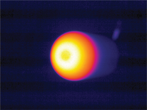
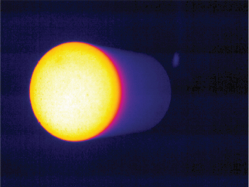
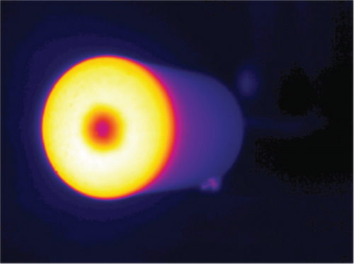
The temperature at the stagnation point of C3 model significantly decreased after the magnetic field was applied. The size of the cooling region is closely related to the green bright spot observed earlier in Figure 38.
Figures 41 and 42 depict the measured surface temperatures and calculated heat flux distributions for models C2 and C3, with and without the externally applied magnetic induction field.
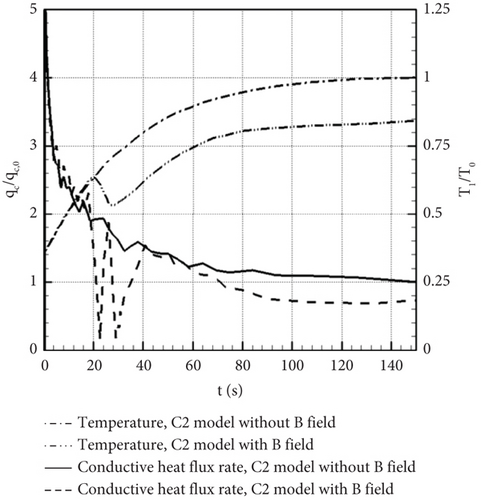
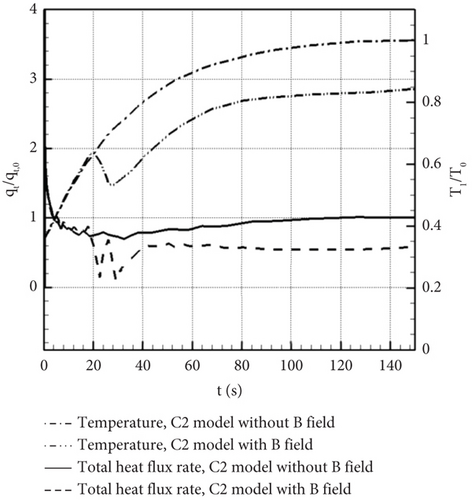
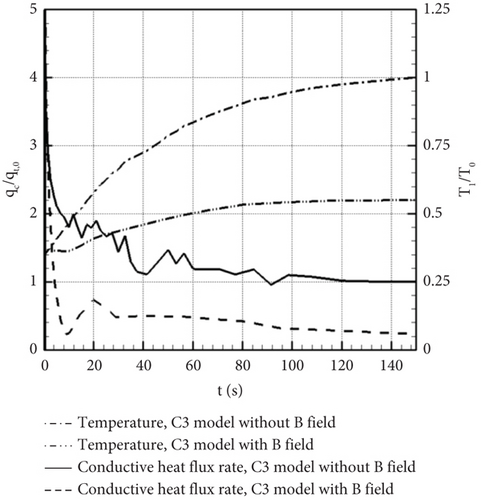
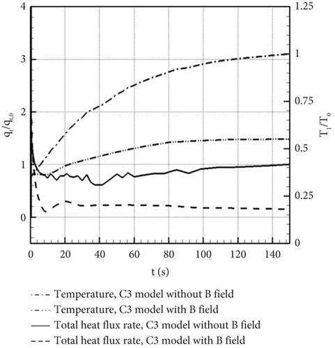
The experimental results indicated that after applying the magnetic field, both the shock wave standoff distance and resistance increased, the pressure increased, the Hall voltage increased, the surface temperature decreased (by 16% for the C2 model and by 44% for the C3 model), and the heat flux decreased (by 46% for the C2 model and by 85% for the C3 model). Owing to the geometric constraints at the nose of the C2 blunt-body model, the magnetic induction intensity in the stagnation region was relatively low, resulting in less noticeable heat flow control effects and delayed heat flux reduction. In contrast, for the C3 model, the electromagnetic field had an immediate impact on the surface temperature and heat flux rate, resulting in better heat reduction effects.
5.3.3.2. Unconventional Findings in Magnetofluiddynamic Thermal Protection
Lineberry and Bityurin [185] conducted magnetic control experiments using a cylindrical model at the TsAGI MHD WT test facility. However, the expected increase in shock standoff distance, redistribution of heat flux, and significant reduction did not occur. The test results before and during the MHD acceleration are presented in Figure 43.
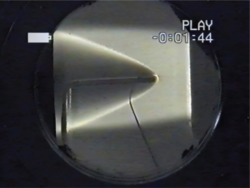

The experimental results indicated that the natural ionization level in the flow field was very low, with the Hall effect playing a dominant role. The MHD effect was minimal in this experiment, and the MHD interaction parameter was irrelevant to the magnetic field size because the square of the Hall parameter far exceeded 1. To observe more pronounced MHD effects under low-pressure conditions, the characteristic size of the MHD interaction region must be 1.0 m or larger, and the required ionization level must exceed 1%. Achieving this condition requires increasing the external ionization (which deviates further from the actual flight conditions) and significant energy consumption. Therefore, this study suggested that onboard MHD systems must consider mitigating the adverse effects of the Hall effect on MHD interactions for better flow control efficiency. Subsequent research results [197] have also indicated that the flow around a magnetically controlled cylinder is primary influenced by two factors: the magnetic field distribution and the Hall effect. The Hall effect depends on the Hall coefficient and the gas properties. A strong Hall effect can lead to decreased conductivity and altered Lorentz forces and energy distribution.
Nowak and Yuen [195] conducted experiments with ionized argon flowing at Ma 4.6 over a hemispherical cylinder model. They measured the magnetically controlled heat reduction effects using both conductive and insulating fluids, with and without an externally applied magnetic field. This study revealed an unexpected result: When an external magnetic field was applied, the stagnation point heat flux increased. In cases where there was no external magnetic field but the fluid was conductive, the empirical formulas by Lees [210] and Fay and Riddell [211] became inadequate because they could not predict changes in the heat flux distribution. The tip of the cone was equipped with a tip electrode, and a ring electrode was placed at the base based on transverse Seebeck effects [212]. The authors measured the heat flux at two points in the model. The study found that when current passed through, the heat flux increased, mirroring the results of Nowak and Yuen [195]. This experiment again posed a challenge to numerical simulations of flow solutions, indicating that the electromagnetic boundary conditions for nonconductive fluids have not been correctly implemented and the boundary conditions for conductive fluids became even more complex, potentially surpassing the conventional physical understanding. Kkn and Reddy [213] conducted magnetic-aerodynamic interaction experiments in two different hypersonic shock tunnel facilities: HST2 and HST3. HST2 simulated low-enthalpy flow conditions, whereas HST3 simulated high-enthalpy flow conditions with a free-stream Mach number of 11 and a total enthalpy of approximately 6 MJ/kg. A rectangular block was used as the model. The results indicated that an external magnetic field increased the total drag and heat flux.
Shang et al. [196] conducted experimental and numerical simulation studies on the bluff body and cone configurations in weakly ionized hypersonic flows. The experimental results indicated that in low-conductivity environments, owing to the rapid decay of the magnetic field from the pole to the bow shock, the magnetic interaction parameter was much less than 1, leading to no significant magnetic-aerodynamic interactions or visible changes in the shock standoff distance. The external magnetic field had minimal impact on the drag of the bluff body in this scenario. To address this problem, it is necessary to enhance the strength and conductivity of the magnetic field. This enhancement can be achieved by increasing the number of coils to shorten the distance between the magnetic poles and the blunt body, thereby enhancing magnetic field strength [145, 214, 215]. By installing tip electrodes at the stagnation point, the breakdown capability in the high-pressure region can be increased to generate a locally higher electron number density and increase the conductivity. As a result of these improvements, the field strength at the stagnation point increased by 1.333 times compared with the previous test results. At the same conductivity, the magnetic interaction parameter nearly doubled. Notably, this experiment confirmed the presence of electrostatic interactions. The charge release creates a structure resembling a boil on a bow shock (bow shock deformation). Therefore, in EMFC experiments, significant electromagnetic effects can be obtained with a lower density plasma flow combined with an external magnetic field, such as using a low-density plasma wind tunnel.
5.3.4. Magnetofluiddynamic Drag Reduction Control Technology
Zhou et al. [197] conducted research on the electromagnetic force-controlled boundary layer drag reduction around a cylinder. The experiments used a two-dimensional laminar flow model with a plasma current (Faraday current) induced by the MHD fluid flowing along the cylinder axis, as shown in Figure 44.
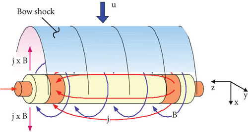
Figure 45 illustrates the experimental setup of the electromagnetic force fluid control used in this experiment.
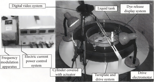
By shielding part of the surface electromagnetic field to alter the spatiotemporal characteristics of the electromagnetic force, the separation point around the cylinder can vary between the front and rear stagnation points, producing different control effects. The results indicated that the electromagnetic forces on the fluid boundary layer could continuously control the flow around the cylinder and the formation of wake vortex streets. Positive electromagnetic forces reduced vortices, dampened oscillations, and decreased drag. Conversely, negative electromagnetic forces had a pronounced vortex-enhancing effect, disrupting the symmetry and stability of the vortex distribution on the surface of the cylinder and exerting a braking effect.
5.3.5. Boundary Layer EMFC
A boundary layer can amplify fluid dynamic disturbances, particularly in the case of high-speed, inviscid hypersonic flows, where the plasma conductivity is relatively low, speeds are high, and interaction parameters are low. This makes EMFC boundary layer more feasible [175]. An external magnetic field has several advantages when applied to plasma control in the boundary layers of high-speed nonequilibrium hypersonic flows. These advantages include not requiring the ionization of large gas volumes, lower flow velocities and density within the boundary layer, and maximum magnetic field strength near the wall, resulting in highly efficient boundary layer flow control. By employing simple surface DC discharge electrodes or generating uniform plasma at the bottom region of the boundary layer through DBD or sliding arc discharge, control over boundary layer flow separation can be achieved. Many researchers have used glow discharges [216] and corona discharges [217, 218] to delay subsonic boundary layer separation on flat plates and enhance wing lift [219–222]. Wilkinson [223] explored the use of spanwise oscillating discharge to reduce Reynolds stresses and surface friction in turbulent boundary layers. Kimmel et al. [224] generated longitudinal DC electric fields between surface electrodes on a flat plate using the discharge effect to increase the surface pressure through boundary layer heating and viscous interactions, effectively controlling boundary layer separation. Macheret et al. [122, 124] also conducted theoretical and experimental research on surface discharge for high-speed boundary layer control, demonstrating that magnetically accelerated plasma columns can influence the flow near the wall and serve as an effective means to accelerate boundary layer flow. Figure 46 illustrates the experimental model of EMFC separation control using plasma discharge and magnetic field control.
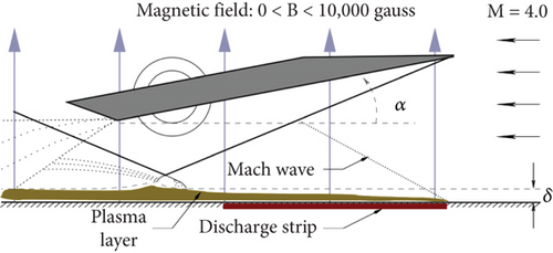
- 1.
For low-ionization fluids, seed particles must be injected into the fluid, ionized, and controlled using Lorentz force actuators.
- 2.
Particles that already possess conductivity are directly controlled by Lorentz force actuators.
- 3.
If neither of the aforementioned options is feasible, then, a glow discharge can be generated in the Lorentz force actuator. However, this third approach can only introduce a small amount of energy into the airflow. The glow discharge is maintained under magnetic field pressure [225–227].
For the second case, Figure 47 illustrates the flat-plate EMFC actuator designed by Macheret et al. [124]. It consists of five surface electrodes separated by a dielectric material. There are four adjustable NdFeB magnets. The Lorentz force is primarily concentrated on the electrodes, particularly at their edges. The magnitude of the Lorentz force generated by the NdFeB magnet section significantly decreases with decreasing height, but still exerts control over the boundary layer.
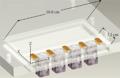
In such an axial arrangement of electrodes, it is important to keep the external electrodes grounded to prevent the generation of reactive forces at the edges of the actuator. Consequently, the distribution of Lorentz forces on the actuator is uneven, which is unavoidable. The effect of making the Lorentz force uniform can be approximated by matching the maximum magnetic field strength with the minimum electric field strength field point and vice versa. Early research indicated that the geometric shape of the segmented electrodes has a significant impact on the electric field distribution [228], enabling adjustments in the electrode geometry when designing MHD actuators. Additionally, as the MHD load coefficient decreases, the location of the maximum Lorentz force gradually shifts from the electrode surface to the magnetic pole.
For the third case, Braun [229] incorporated three components, as shown in the diagram below, and experiments were conducted in a low-speed wind tunnel at atmospheric pressure.
The structure of the Lorentz force actuator includes a row of embedded surface electrodes alternating with NdFeB magnets oriented perpendicular to the flow direction. The conductive particle seeding system and ionization actuator operate by seeding low-ionization-energy potassium carbonate particles into the airflow, which are then ionized by a high-voltage field before entering the active EMFC actuator.
The ionization actuator is responsible for generating the glow discharge. However, PIV imaging revealed that the changes occurring in the boundary layer under the influence of the glow discharge were primarily caused by the Joule heating effect, rather than Lorentz forces.
As can be seen from Figure 48, the conductive particle seeding system employs potassium carbonate seeds as ionizing seeds. Although high-voltage fields can ionize air and produce glow discharge, potassium carbonate seeds are essentially unaffected. Therefore, it is suggested that potassium carbonate seeds should be thermally decomposed or vaporized using high-voltage and high-current pulses.
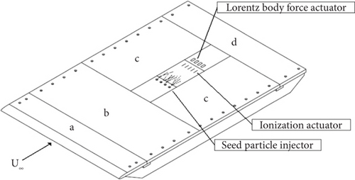
Figure 49 illustrates the results of an EMFC experiment using saltwater, where the EMFC control effect is visualized by the addition of a blue dye. Magnets were placed beneath the surface between the electrodes and upon the activation of the power source, a significant portion of the liquid layer instantly moved forward. Figures 49a, 49b, 49c, and 49d illustrate the time-evolving process of the Lorentz force actuator’s driving effect.

This study suggested that the optimal application for utilizing onboard EMFC may lie in enhancing the control of high-speed missiles. Figure 50 depicts the future development of missile control envisioned in this context. Segmented electrodes are arranged around the missile diameter, enabling control initiation from various positions around the missile to manipulate its direction. Bookey et al. [230] conducted experimental research involving the excitation of plasma discharge at the tips of low-altitude supersonic projectiles to alter aircraft orientation. By providing a discharge between two electrodes via a high-voltage generator, disturbances were induced between the aircraft’s surface and the shock waves at the tip of the conical body. The intensity of these disturbances caused the shock waves to twist and deform, resulting in changes in aerothermodynamic variables and generating lateral forces and pitch moments that redirected the projectile.
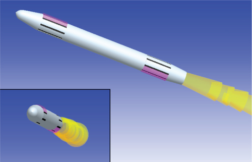
Braun [229] summarized information related to EMFC and relevant experiments, introducing the application of artificially added conductive seed particles to boundary layer flow control. This information is presented in Table 8.
| Mach num. | σ, ℧/m | p, torr | B, T | Magnet type | Ionization source | Medium | Configuration |
|---|---|---|---|---|---|---|---|
| Low speed | 3.2 | 1300 | ≈0.4 | NdFeB | N/A | Saltwater | Flat plate |
| 5.8 | 1–2.5 | 1.2~2 | 0~2 | Electromagnet | High-voltage DC | Air | Blunt body |
| 4 | ≈0.01 | 6~8 | ≈0.4 | NdFeB | High-voltage RF | He, N2 | Channel |
| 4 | 0.05~0.1 | 2~10 | 0.45 | NdFeB | High-voltage RF | He | Channel |
| 3 | 0.02~0.12 | 12~15 | 0~1.5 | Electromagnet | High-voltage RF | N2 | Channel |
| Low speed | ≈3 | 760 | ≈0.4 | NdFeB | N/A | Saltwater | Flat plate |
| 3,4 | 0.08~0.18 | 7~20 | 0~1.75 | Electromagnet | High-voltage RF | N2, air | Channel |
| 5,1 | ≈1 | 0.6 | 0.1~0.2 | Electromagnet | High-voltage DC | Air | Flat plate |
| 3,4 | 0.14~0.23 | 7~20 | 0~1.5 | Electromagnet | High-voltage RF | N2, air | Channel |
| 5.1 | ≈1 | 0.8 | 0.2 | Electromagnet | HV,10 Hz—RF | Air | Flat plate |
| 5 | 2 | 0.6~7 | 0~1 | Em, NdFeB | HV DC,RF rad. | Air | Flat plate |
| 3 | ≈0.1 | 7~20 | 0~1.5 | Electromagnet | High-voltage RF | He, N2 | Channel |
| 3 | ≈0.07 | 7~20 | 0~1.5 | Electromagnet | High-voltage RF | He, air, N2 | Channel |
| 3 | ≈0.1 | 7~20 | 0~1.5 | Electromagnet | High-voltage RF | Air, N2 | Channel |
| 2.8 | N/A | 28 | 0~2 | Superconducting | Plasma column | Air | Channel |
| 3 | ≈0.1 | 7~20 | 0~1.5 | Electromagnet | HV RF, seeding | Air, N2 | Channel |
| 5.3 | 0.06 | ≈0.6 | 0~1 | Electromagnet | High-voltage DC | Air | Flat plate |
| 3 | ≈0.1 | 7~20 | 0~1.5 | Electromagnet | High-voltage RF | Air, N2 | Channel |
| 2.8 | N/A | 28 | 0~4.5 | Superconducting | Plasma column | Air | Wedge |
| 4 | ≈0.1 | 4.8 | 0~1.63 | Electromagnet | High-voltage RF | N2 | Channel |
| 2.6 | N/A | 28 | 0~4.5 | Superconducting | Plasma column | Air | Wedge |
| 5.15 | ≈1 | 0.6 | 0~0.2 | Electromagnet | High-voltage DC | Air | Flat pl., inlet |
Gallitis and Lielausis [231] designed an electromagnetic field activation plate with alternating strip electrodes and magnetic poles, immersed it in a weak electrolyte solution, and for the first time, experimentally confirmed that the Lorentz force could alter the boundary layer structure of a flow field with a certain level of conductivity. Udagawa et al. [172] conducted experiments on EMFC boundary layer in a supersonic flow with a Mach number of 1.5. Their experimental system consisted of two types of components: a supersonic wind tunnel driven by a shock tube and sensors, as shown in Figure 51.

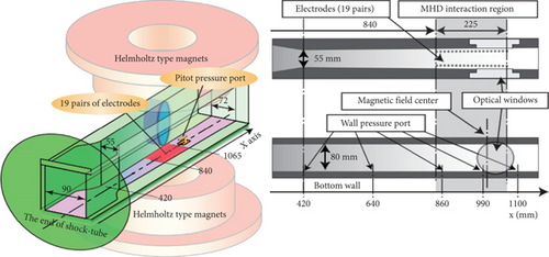
Their experiments involved an analysis of the pressure distribution, wall pressure distribution, and effect of the electromotive force on DC discharge in the boundary layer. The control effect on the boundary layer was altered by changing the position of the oblique shock wave.
Bityurin et al. [194, 232] conducted EMFC and MHD power extraction experiments in an HFP wind tunnel in Russia. The results of these experiments demonstrated that the Lorentz force can control boundary layer separation, alter turbulence, and redistribute pressure and heat flux on the surface of an aircraft. This optimization enhances the operational efficiency of ramjet and scramjet engines, controls ignition, improves combustion in the combustion chamber, and generates onboard electrical power.
Figure 52 illustrates the EMFC separation device developed by Minton [169]. A shock wave generator is placed in the airflow in the wind tunnel at an angle of attack α to generate oblique shock waves. At high angles of attack, the intensity of the shock waves causes airflow separation downstream of the shock wave point. The electrode used for plasma discharge is located upstream of the shock wave point. Electromagnetic coils are positioned in the flow field, creating a magnetic field perpendicular to the flow and discharge current directions.
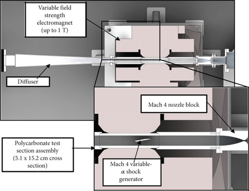
The surface of the model generates a magnetic field of approximately 2 T in its vicinity. The visualized flow pattern of the measured MHD interaction region is shown in Figure 53, where the angle of attack of the airflow is approximately 2.0°. Strong magnetic fluid interactions can be observed on the underside of the plate.

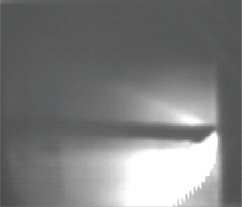
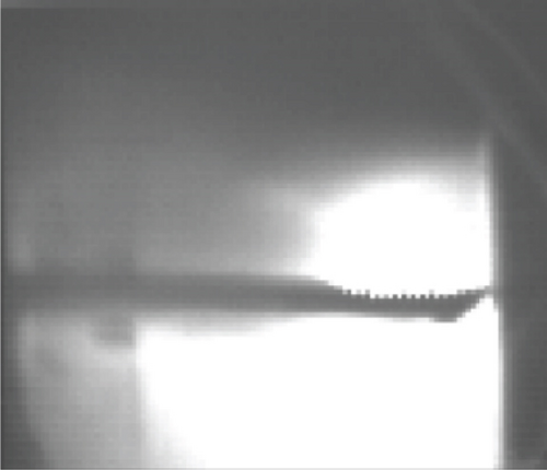
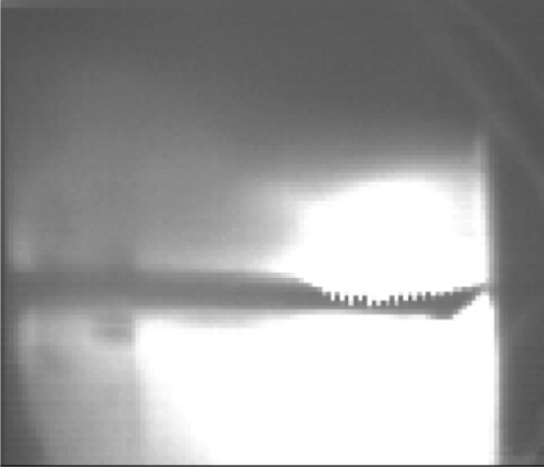
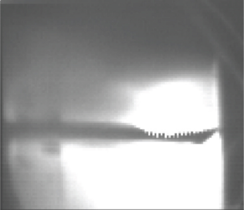

The excitation generator kept the positions of the reflected excitation waves roughly constant and independent of the angle of attack α, which determined the EMFC separation performance based on the specific parameters presented in Figure 54.
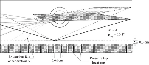
It can be seen that for a Mach number of 4, flow separation is expected to occur at α = 10.1∘.
This formula yields the pressure increase across a reflected shock wave. Beyond this pressure, the boundary layer separates. After continuously increasing the Mach number using a rotating shock wave generator, at Mach 5, the pressure rise across the reflected shock wave reached the critical pressure that induced boundary layer separation. At this point, the separation region was sufficiently large, and the EMFC separation system was activated. This accelerated the flow ahead of the reflection point to a level that allowed the boundary layer to pass through a significant adverse pressure gradient without separation. The performance characteristics of this flow control system can be studied by adjusting the magnetic field intensity and input power of the discharge.
Figure 55 depicts the experimental results of the surface pressure variation over time under the influence of discharge. Plasma discharge was initiated at 20 s and terminated at 40 s.
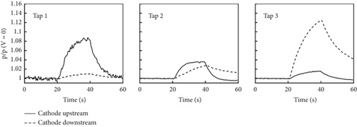
When a magnetic field is applied perpendicular or parallel to the surface of the weakly ionized plasma generated in the boundary layer, it affects the plasma distribution in the magnetic field, thereby altering the flow field morphology. Therefore, this study was extended by applying a transverse magnetic field parallel to the surface of the plate and perpendicular to the direction of the free-stream velocity. The magnetic field was varied from 0 to 1 T, and the total current was varied from 0.025 to 0.3 amp. After applying an external magnetic field, the Lorentz force vector directed toward the plate surface suppressed the increase in the surface pressure. However, the results indicated that the primary effect influencing the flow was the Joule heating effect in the boundary layer fluid, rather than the Lorentz force effect. Macheret et al. [124] also noted that the EHD effect could alter the velocity at low densities in combination with the Joule heating effect. Studies related to surface microwave discharge [234] have suggested that local heating in a flow generated by Joule heating effects is accompanied by an increase in pressure and boundary layer displacement.
Menart et al. [145] observed that in the absence of an external magnetic field, a continuous surface DC discharge at Mach 5 led to a localized increase in the static pressure on a flat plate. The discharge, which was oriented in the flow direction on the plate, triggered a Joule heating effect in the fluid, which was the primary cause of the increased boundary layer thickness and pressure, rather than the Lorentz force effect introduced by an external magnetic field. Subsequent measurements performed by Kimmel et al. [235] confirmed this trend. Kimmel et al. [224] further summarized and expanded the findings. Specifically, the influence of an external magnetic field on the pressure distribution, applied voltage, and glow discharge was analyzed. The results indicated that without an external magnetic field, surface discharge could control the pressure field around the flat plate with the pressure increment caused by the discharge roughly following a linear relationship with the discharge power. Notably, as a result of the nonuniformity of the discharge near the cathode, the effect of the constriction discharge was more pronounced near the cathode and less significant downstream. Under an external magnetic field, when the current was less than 100 mA and the magnetic field was less than approximately 0.2 T, the discharge tended to diffuse. As the current and magnetic field intensities increased, the discharge range narrowed. Furthermore, when the Lorentz force vector pushed the discharge downward, the pressure increased, and this effect became more pronounced as the distance along the plate increased. However, considering the three-dimensional nature of discharge, its dependence on the magnetic field, and Joule heating effect in the boundary layer, it is unclear whether these effects were solely caused by Joule heating. When the Lorentz force vector pointed upward, the discharge was pushed away from the flat plate, leading to a decrease in pressure, as shown in Figure 56.
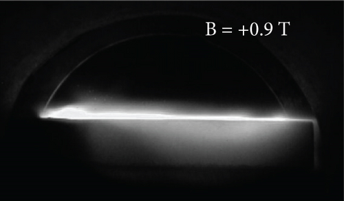
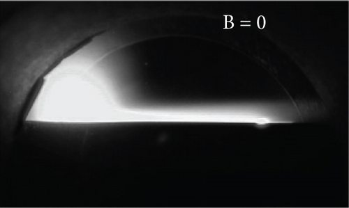
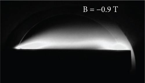
Miles et al. [236] and the Princeton University Applied Physics Group led by Zaidi et al. [237] explored the control of boundary layers using “sliding arc” magnetically driven nonequilibrium surface discharge. In experimental studies, surface arc discharges occurred between two nearly parallel (conical, forming plasma columns upstream) linear electrodes spaced at a certain distance. The electrodes were positioned on the surface and along the flow direction (as shown in Figure 57). The graphical results in Figure 58 indicate that when a high voltage was applied between the electrodes, a contracting plasma column was formed at the minimum separation point (the plasma column was generated by a DC breakdown between the two surface electrodes). This position moved upstream when gradually reducing the gap between the electrodes. According to the results in Figure 59, subsequently, the plasma column was convected by the airflow and flowed downstream at the end of the electrodes. At this point, another plasma column was formed upstream, and this process was repeated. As a result of the fast flow velocity, the discharge appeared approximately uniform to the naked eye. However, when imaged with a high-speed camera, plasma columns could be observed.
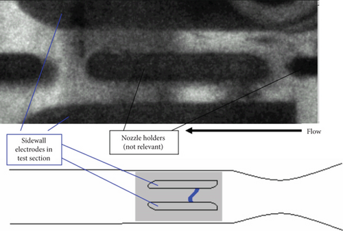

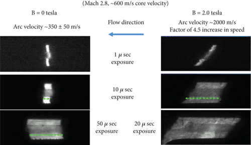
These results indicate that when a magnetic field orthogonal to both the plasma column and flow is applied, MHD forces accelerate the plasma column and transfer momentum to the neutral gas, accelerating the flow after surface discharge from electrodes is added compared to the average local flow velocity after the application of a moderate-strength magnetic field (B = 0.5 ~ 3.0 T).
Kalra et al. found that EMFC boundary layer experiments was precisely determined by the momentum transfer of a plasma column generated after the addition of electrodes. The plasma column formed a periodic structure with frequencies ranging from to 1 to 10 kHz between the electrodes and the frequency depended on the current and magnetic field strength. Macheret’s [122] experimental results suggested that a plasma column can act as a unidirectional porous piston for flow control. Under the influence of a magnetic field, the ions in a plasma column flow rapidly downstream and collide with neutral particles, transferring momentum to the boundary layer. In Kalra et al.’s [119] subsequent study, investigations were conducted on the magnetic control effect of an additional electromagnetic field. The results indicate that although the combined action of electric and magnetic fields can provide greater momentum to the flow, simply increasing the current does not necessarily improve the MHD effect. When a shock-induced separation bubble moves downstream, Joule heating occurs. Beyond a certain point, an increase in the current begins to have an inhibitory effect as a result of Joule heating.
Kalra et al. [121] further studied the impact of magnetically driven surface plasma columns on separation caused by shock–boundary layer interactions and introduced the concept of the “snowplow arc.” Surface plasma columns manifest as lateral “arcs” between two bifurcated electrodes that are driven by Lorentz forces to sweep over the gas near the surface either downstream or upstream. In Kalra et al.’s experiments, the wind tunnel had a Mach number of 2.8, and a 10° wedge was used to generate oblique shock waves that impinged on the plane where the plasma actuator was located.
A schematic of the experimental setup is presented in Figure 60. A uniform magnetic field was applied vertically throughout the apparatus, and the plasma column generated between the electrodes was subjected to forces produced by magnetic field B and current J in the upstream or downstream direction.
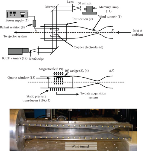
Figure 61 presents the shadowgraph results of the experiment. The shock wave caused a gradual increase in the static pressure near the wall, leading to separation. A reflected shock wave appeared after the incident shock wave interacted with the boundary layer.
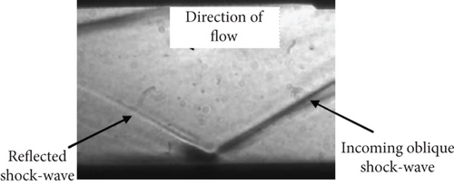
The experimental results indicated that the coupling between the plasma column and SWBLI region led to a shift in the location of the shock wave–induced boundary layer separation point. When the Lorentz force acted upstream, the separation point also moved upstream. When the Lorentz force acted downstream, the separation point was largely unaffected. This study quantitatively highlighted the reasons for the undisturbed downstream behavior by calculating the ratio of the plasma column scale to the boundary layer thickness.
This study also evaluated the effects of electromagnetic field location, magnetic field line angle, and electrode placement using four different testing configurations, as represented in Figure 62. In Case 1, boundary layer driving was performed using surface-embedded copper electrodes, and the electrodes were powered by a DC power source upstream. The magnetic field was perpendicular to both the direction of the current and flow direction, generating Lorentz forces that caused upstream flow of the plasma column. Under these control conditions, the intensity of the separation bubbles increased. In Case 2, the electrode configuration was the same as in Case 1, but the electrode positions shifted from upstream to downstream. The Lorentz forces generated by the magnetic field caused the plasma column to move downstream. Under these control conditions, flow separation was eliminated or separation bubble intensity decreased. In Case 3, the electrode setup was the same as that in Case 1, but the magnetic field lines were bent at a small angle, causing the plasma column to move from the wall into the incoming flow, forcing a high-momentum incoming flow into the separated boundary layer, thereby reducing separation. In strong interactions, separation can be eliminated. In Case 4, there were two concentric electrodes, and after applying a magnetic field perpendicular to the electrode plane, the plasma column rotated, leading to the formation of vortices in the subsonic boundary layer.
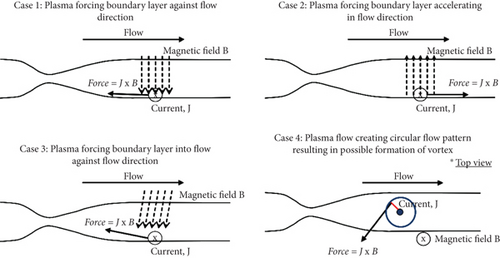
The results indicated that compared to the baseline condition (Case 1), when Case 3 increased the applied magnetic field angle from 0° to 10°, the separation decreased. However, further increasing the angle to 20° did not reduce the separation.
In an experimental study on controlling shock wave–induced separation using MHD effects, Thibault and Rossi [238] conducted flat-plate tests with saltwater flow and obtained a boundary layer velocity distribution, as shown in Figure 63, which aligns with the conditions of Case 2 in the aforementioned study by Kalra et al. [121].
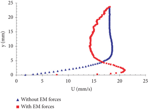
Kalra et al. [121] further analyzed the impact of wedge angles and compared the results of tests with 10° and 14° oblique wedges. The 10° oblique wedge corresponded to a lower shock wave intensity, and as the higher downstream pressure gradually penetrated the subsonic region of the boundary layer along the upstream side of the shock wave point, it did not induce recirculation bubbles or separation without plasma driving. However, when the oblique wedge angle increased from 10° to 14°, the oblique shock wave collided with the turbulent boundary layer, leading to bubble separation. At this point, driving the plasma downstream in the direction of the reverse separation bubble altered the geometry of the disturbance region. Additionally, applying a magnetic field at a certain angle allowed the plasma column to enter the boundary layer, increase the momentum of the boundary layer, and prevent separation.
Bookey et al. [230] revalidated the EMFC results for 10° and 14° oblique wedges. The results indicated that compared to the 10° oblique wedge, the reflected shock wave in the flow field of the 14° oblique wedge occurred before the incident oblique shock wave interacted with the boundary layer. When separation occurred, the increased thickness of the boundary layer led to the observation of a reflected shock wave before it collided with the boundary layer. A shadowgraph of the disturbance region is presented in Figure 64.
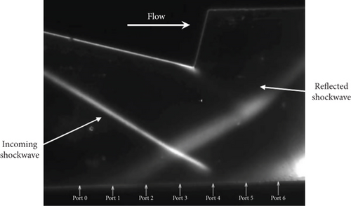
Furthermore, as shown in Figure 65, the wall pressure exhibits a plateau in the middle, indicating that the interaction described above resulted in separation.

Kalra experimentally investigated the interaction between magnetically forced discharge and boundary layer flow. Images of the plasma columns within the flow field are demonstrated in Figure 66. Instantaneous images of the plasma columns revealed an approximate diameter of 1 mm. With extended exposure times, as shown in the image of the plasma columns progressing along the electrodes in part (a), it becomes evident that the plasma columns move toward the end of the electrode. Based on the limited length of the electrodes, the plasma columns were eventually extinguished and reignited at the shortest distance between the two electrodes. When oblique shock waves are not generated, there is no separation zone. However, as shown in part (b), the oblique wedge generates shock waves, causing boundary layer separation. In this image, the plasma columns do not reach the end of the electrode. This is because as the local flow separated and moved upstream, the plasma columns could not be dragged to the end of the electrodes in the absence of a magnetic field.
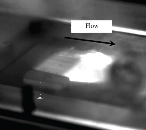
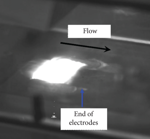
The findings demonstrated in Figure 67 present the flow field Schlieren patterns corresponding to the presence or absence of a magnetic field under a constant plasma power input.


The length “l” represents the distance covered after the first compression wave interaction when the incident oblique shock wave separated from the boundary layer. One can see that this distance increases when an external magnetic field is applied.
Scaling of the effect of the Lorentz forces on the local interaction parameters within the boundary layer can be achieved by varying the mean values. Experimental studies on MHD effect conducted on compressible and incompressible [117] flows in the boundary layer have indicated that the interaction parameters significantly influenced the effectiveness of EMFC. Therefore, these interaction parameters can be considered indicators of magnetic control effects.
In Lineberry and Bityurin’s [185] research on EMFC inlets, the MHD interaction parameter “Su” was defined as follows: Su ∝ σu2B2L, where s represents the conductivity, u is the velocity, B denotes the magnetic field strength, and L signifies the length. They determined that maximizing both the conductivity and magnetic field strength is necessary to achieve a sufficient MHD interaction. For moderate magnetic field intensities (0.1–0.5 T), the characteristic scale of the corresponding MHD interaction region must be at least 1 m, and the required ionization level must exceed 1%. The former necessitates a large-scale testing rig, and the latter is challenging to achieve, even with external ionization sources, because energy consumption exceeds expectations.
In the analysis of Henoch and Stace’s [117] experiments on turbulent electrolytes and flat-plate boundary layer EMFC, it was suggested that friction velocity can serve as an improved interaction parameter for measuring velocity scales. This was also acknowledged by Macheret et al. [124] in subsequent research. For laminar flat-plate boundary layers, the surface friction is inversely proportional to the square root of the Reynolds number, and the ratio of the velocity thickness to the flow length is inversely proportional to the square root of the Reynolds number (i.e., cf = C1Re−1/2). Therefore, based on the friction velocity, the interaction was determined to be . The values of C1 and C2 can be derived based on experimental conditions to obtain similar solutions for laminar boundary layers and subsequently deduce their values.
6. Conclusion
- 1.
Different wind tunnel types serve various testing functions. Among these, high-enthalpy shock tunnels have distinct advantages because they can generate extremely high temperatures and pressures. Despite the short effective testing time, achieving the effective magnetic control environment of a real flight is possible if supplemented with advanced driving technology, flow field detection methods, and testing techniques. However, the low degree of ionization of incoming flows in high-enthalpy shock tunnels places higher demands on simulation speed and magnetic field strength.
- 2.
Most experimental research related to EMFC is still conducted in simplified flow environments (flat plates, inclined wedges, blunt bodies, etc.), and detailed and comprehensive studies on power consumption under real flight conditions, model scaling, and hypersonic interactions are required. Research should also transition from simple to complex configurations. Additionally, experiments should consider practical electrodynamic boundary conditions and address changes caused by small model sizes.
- 3.
The primary conditions for implementing onboard magnetohydrodynamic technology are as follows: providing a sufficiently conductive airflow and optimizing the design of the magnetic control system (e.g., modifying the magnetic interaction parameters) while also considering changes in magnet size and weight. Therefore, magnet selection is crucial. ReBCO as one of the HTSs has been developed to address this issue, while extensive active cooling measures may be needed in hot aerodynamic environments. If the strength and cooling issues can be resolved, then, EMFC should be more effective than plasma jet control in terms of rapid actuation effects. Otherwise, plasma jet control, which provides rapid actuation effects, may be advantageous. Furthermore, magnetohydrodynamic onboard systems must eliminate the adverse impact of the Hall effect for better flow control efficiency.
- 4.
Regarding the two requirements of EMFC, namely, high power and conducting currents, power extraction technologies can be developed using magnetohydrodynamic generators to extract surface energy along with pulsed direct current discharges. To increase gas conductivity, ionized gas, ion jet sources, and discharge technologies needed to be developed.
- 5.
Regarding the experimental research conclusions in the field of magnetohydrodynamic acceleration and propulsion, it has been observed that reducing the electrode area enhances magnetohydrodynamic effects, leading to increased gas acceleration and thrust, primarily determined by the Joule heating effect.
- 6.
Magnetohydrodynamic flow control of the inlets primarily involves changing the position of the shock waves in the inlet under off-design Mach numbers, enabling the inlet shock waves to reconverge at the lip. The feasibility of magnetohydrodynamic control in simplified configuration flows has been demonstrated.
- 7.
The experimental conclusions regarding shock standoff distance control and the related heat reduction through magnetic control were inclusive. Some experiments increased the shock standoff distance and achieved thermal protection by applying a magnetic field to generate Lorentz forces, whereas others did not observe significant increases in the bow shock standoff distance or substantial reductions in the heat flux. These differences may be attributed to factors such as differences in model geometry (nose region effects), Hall electric fields, and electrostatic phenomena. To address this disparity, it is recommended to enhance the magnetic field strength and conductivity as much as possible without significantly deviating from actual flight conditions. For example, this can be achieved by installing tip electrodes at the stagnation point and using lower density plasma flows combined with an external magnetic field, such as flowing through a low-density plasma wind tunnel, to obtain significant electromagnetic effects while minimizing the impact of electrostatic phenomena. Additionally, attention should be paid to the influence of the electromagnetic boundary conditions.
- 8.
Experiments on drag reduction in the boundary layer around a cylinder controlled by electromagnetic forces were conducted. The results showed that positive electromagnetic forces effectively suppressed vortices and dampened oscillations. They also contributed to drag reduction. In contrast, negative electromagnetic forces noticeably enhanced vortex formation. This effect can disrupt the symmetry and stability of the vortex distribution on a cylindrical surface and exert a certain level of braking effect.
- 1.
Two approaches can be considered on handling the stiffness introduced by chemical reactions in the coupled high-temperature thermodynamic nonequilibrium multicomponent gas model:
- a.
Separating the nonequilibrium source terms for independent computation. This is similar to employing a preconditioning technique to calculate the diagonal terms of the chemical source, introducing some additional error, and yielding only first-order accuracy in time.
- b.
Coupling the nonequilibrium terms with the inviscid and viscous terms. This approach results in larger computational effort and time consumption. To mitigate this, reducing the time step and using implicit methods for time preprocessing (implicit treatment for convection terms, partially implicit treatment for source terms, and fully implicit treatment for inviscid and viscous flux portions) can be employed.
- a.
- 2.
Model corrections in turbulence simulation: Turbulence models can be improved through the addition of correction terms, obtained through various methods such as implicit schemes, data mining, machine learning, and discrete adjoint methods. After introducing external electromagnetic fields, further attention should be given to the effects of these fields on turbulence fluctuations and Reynolds stresses, necessitating additional turbulence model corrections.
- 3.
Numerical stiffness issues and divergence constraints introduced by coupled electromagnetic fields: Challenges arising from the coupling of electromagnetic fields include the following:
- a.
Numerical stiffness and instability issues were observed in the source terms. These issues were attributed to factors such as high conductivity, which leads to large current densities. Rapid variations in the source terms were also noted due to the speed of light being much faster than the flow velocities. Solution: Develop strongly conservative forms of coupled magnetohydrodynamic equations.
- b.
The parabolic nature of the equations occurs when magnetic fields approach diffusive limits. Solution: Utilize a virtual time step that forces the equations to become hyperbolic within a virtual time frame, regardless of the physical time.
- c.
Inconsistencies in time scales between flow and plasma lead to significant variations in eigenvalues due to the stiffness in the source terms. Solution: Develop virtual time–based preprocessing techniques to accelerate convergence in steady-state simulations.
- d.
Magnetic field divergence cleaning. In numerical shock simulations, nonphysical intermediate states exist, making it challenging to satisfy the divergence-free condition ∇⋅B = 0. Solution: Enhance divergence constraint enforcement through methods such as projection techniques, constrained transport schemes, the eight-wave solver approach, and hyperbolic divergence cleaning methods.
- e.
The accuracy of computed results for coupled electromagnetic fields in disturbed flow fields with shock/turbulence interactions: Most turbulence models require the calculation of wall attenuation functions to determine wall distances. However, considering the unknown effects of electromagnetic fields on wall attenuation functions, it becomes challenging to accurately represent the coupling of turbulence and electromagnetic fields. Solution: Modify turbulence models with magnetohydrodynamic corrections. Corrections can be made from the perspectives of anisotropy, linear Joule dissipation characteristics, and multilayer flow characteristics. However, it is essential to recognize that current assumptions about conductivity models are relatively simplistic, and more precise conductivity modeling is required to better simulate real flows.
- a.
As to numerical simulations in EMFC for hypersonic shock–boundary layer interactions, the mechanism of EMFC for shock–boundary layer interactions can be analyzed from two perspectives: dynamic effects and changes in physical properties. Effective elimination of separation can be achieved when the magnetic field or load coefficient is sufficiently large. Furthermore, the best control results are obtained when the magnetic field acts perpendicular to the wall surface. Control effectiveness is also maximized when the magnetic field affects the “neck” region of the compression corner. The closer the magnetic control is to the wall surface, the better the separation control. The Joule heating effect in electromagnetic flow weakens the separation control effect of the accelerating Lorentz force. The Lorentz force must be sufficiently strong to counteract the boundary layer thickening caused by Joule heating. This can be achieved through improvements in discharge models for simulation to assist in determining the maximum heat input.
In the field of EMFC for shock–boundary layer interactions, further research can be focused on several aspects: the types of magnetic fields related to shock–boundary layer interaction, the distribution of electromagnetic fields, optimization methods for electromagnetic fields, etc.
Current research on EMFC for shock–boundary layer interactions primarily focuses on two-dimensional models and flow field, such as flat plates, channels, and compression corners. Future studies can expand to analyze three-dimensional effects. Additionally, the choice of compression corner angles is based on aircraft configuration and typically falls within the range of 14°–38°. Future research can explore larger compression corner angles to get better understanding on shock–boundary layer interaction mechanism.
Conflicts of Interest
The authors declare no conflicts of interest.
Funding
This work was supported by the National Key R&D Program of China (grant number 2019YFA0405300).
Acknowledgments
This work was supported by the National Key R&D Program of China (grant number 2019YFA0405300).
Open Research
Data Availability Statement
Data availability is not applicable to this article as to new data were created or analyzed in this study.


