Numerical Simulation of Plasma Plume Sheath and Secondary Electron Emission Based on DSMC-PIC Parallel Algorithm
Abstract
The temporal and spatial evolution of plasma plume is accompanied by sheath, secondary electron emission (SEE), and other phenomena that have a crucial impact on the working characteristics and performance improvement of plasma devices. In this paper, a direct simulation Monte Carlo (DSMC) and particle-in-cell (PIC) hybrid parallel algorithm is employed for numerical simulation, which is a fully kinetic PIC method. Energy-based outlet and wall boundary conditions of charge conservation are investigated. This paper discusses the influence of different models on the flow field. First, four SEE energy spectrum models—the Mozorov model, the Furman model, the vertical model, and the three temperature model—are discussed. Then, four kinds of insulation wall materials—boron nitride, silicon carbide, alumina, and graphite—as simulated by the modified Mozorov coefficient model are investigated. Through the simulation of axisymmetric cases, the influence of SEE energy spectrum; secondary electron emission coefficient (SEC); electric field action; and other factors on the spatiotemporal evolution of H2, H, X, , H+, and e in the flow field is demonstrated. This paper analyzes the structural characteristics of cloud images with different models through number densities in detail. The SEE energy spectrum has an important influence on the distribution of the field potential and the number density of charged particles, but it is not as important as the SEC.
1. Introduction
Plasma plumes are widely found in electric propulsion [1], material surface modification [2], and nuclear reactors [3]. Plasma plumes are generally composed of neutral particles and charged ions, also a kind of supersonic flow [4]. When a plasma plume interacts with a wall, a variety of physical phenomena will occur, including the reflection of neutral particles, chemical reaction on the wall, and charged particles forming a sheath and generating secondary electrons. The above phenomena have an important impact on the spatiotemporal evolution of the plasma plume and are crucial for improving the performance of plasma devices. In previous studies of plasma plumes, the mainstream flow was studied, and the properties of the sheath and secondary electron emission were often studied separately, with few studies of their interaction with the flow field.
Zhang [5] established a two-dimensional particle-in-cell (PIC) model of the Hall thruster channel and studied the relationship between the insulation wall sheath and the conduction current near the wall. Qin [6] studied the influence of the wall secondary electron emission coefficient (SEC) on the discharge characteristics of a Hall thruster. Gunjan et al. [7] studied the hydrodynamic sheath model containing two different electrons under an electron-emitting condition. The ion-neutral collision is investigated. The study reveals that the secondary electron population and space charge deposition near the wall depend on electron nonextensivity. Boerner and Boyd [8] used four different electron models to simulate the nonequilibrium plasma sheath. Simulations based on the DSMC-PIC method using the Boltzmann and Poisson-consistent models produce sheath structures that are in excellent agreement with the planar Bohm sheath solution near the center line of the probe. In 2013, Hara and Boyd [9] used a direct kinetic simulation [10] in which the Vlasov equation is solved to directly obtain the velocity distributions of the plasma components and is used to model the collisionless sheath in the presence of SEE. Gatsonis and Yin [11] developed a PPT plume model that is axisymmetric and based on a hybrid particle-fluid approach. Neutrals and ions are modeled with a combination of the DSMC and a hybrid PIC method. Electrons are modeled as a massless fluid with a momentum equation that includes electric fields, pressure gradients, and collisional contributions from ions and neutrals. In 2018, Averkin and Gatsonis [12] developed an unstructured electrostatic particle-in-cell (EUPIC) method on arbitrary tetrahedral grids for the simulation of plasmas bounded by arbitrary geometries. Analysis shows the second order of convergence for the potential and the first order of convergence for the electric field and charge density. Vatansever, Nuwal, and Levin [13] used the PIC-DSMC method to model thermionic emissions from an emitting wall in partially ionized boundary layer plasmas in the hypersonic regime. Emissive sheaths submersed in a high-density (1016 m−3) plasma are examined using a PIC-DSMC solver, CHAOS [14]. They find that thermionic emission from the wall can be increased by 8% compared to the collisionless case. Taccogna and Minelli [15] attempted to correlate the different mechanisms contributing to electron transport by means of a fully kinetic three-dimensional PIC model. The effect of secondary electron emission from walls works as an auxiliary mechanism (together with ion heating and azimuthal rotation) to saturate the electron drift instability, leading to smaller amplitude oscillations.
Li et al. [16], based on the DSMC-PIC method, numerically simulated the diffusion and development process of three-dimensional unsteady vacuum arc neutral particles with dissociation and combination reactions, as well as the steady axisymmetric plasma plume with dissociation and combination reactions. The results showed that more particles experienced dissociation reactions compared to combination reactions. Li et al. [17] established three DSMC models of plasma plume with wall effects. The coupling effect of gas wall effects and the electric field was investigated by the PIC method while ignoring the influence of sheath. Our research group has studied the interaction between neutral particles and the wall, as seen in Ref. [17]. In this paper, the parallel DSMC-PIC algorithm [18] is used to study the influence of sheath and secondary electron emission using a variety of physical models. According to the fully kinetic method, the numerical algorithm of Possion’s equation is developed. According to the physical process, a wall boundary condition for charge conservation and an energy-based outlet boundary condition are proposed.
2. Physical Model
Neutral particle reflection, chemical reaction, and ion–wall interaction models can be found in Ref. [17]. This section mainly discusses the SEC and secondary electron emission energy spectrum (SES) models, the DSMC-PIC method, especially the electric field solver, wall boundary conditions for charge conservation, and energy-based outlet boundary conditions.
2.1. SEC Models
More details about the above four improved models can be found in Ref. [20].
2.2. SES Models
The velocity distribution of the emitted electrons caused by the single electron incident is very complex and presents a bimodal morphology. However, the total secondary electron velocity distribution caused by the initial or non-Maxwell distribution electrons presents a single peak morphology similar to the Maxwell distribution. Therefore, only the total velocity distribution of all outgoing electrons is considered, and it is assumed that all outgoing electrons obey the isotropic Maxwell distribution [21]. For SES models, the ratio κ of the incident electron temperature Te0 to the outgoing electron temperature Tew is often used to describe the overall distribution of the emitted electrons according to the energy change after the interaction between the electrons and the wall. For example, in Mozorov’s model, κ is one-half at low electron temperatures and one-third at high electron temperatures. In Furman’s model, κ is one-third at low electron temperatures and one-half at high electron temperatures.
In Equation (7), represents the average energy of emitted electrons in the direction perpendicular to the wall.
2.3. DSMC-PIC Hybrid Method
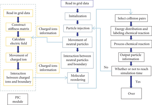
The DSMC method is well known to simulate the physical processes of neutral particles, including collisions, chemical reactions, and gas–surface interaction. The details of our DSMC method are described in [23]. The rough descriptions of the DSMC-PIC hybrid method can be found in Figure 1, and more details of our DSMC-PIC hybrid method are described in our previous work [18].
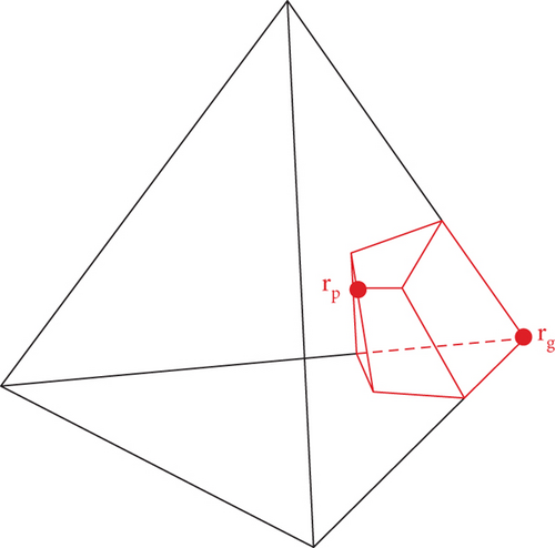
When building the Jacobian matrix J ≡ ∂R/∂ϕ, in the program, the term ∇(ε∇ϕ) is discretized into a stiffness matrix K.
Thus, the main difference between matrix K and matrix J is the values on the diagonal. You only need to add the value on the diagonal line when calculating matrix J from K. After matrix J is constructed, PETSC is called for a parallel solution without iterative calculations.
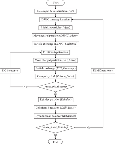
3. Computational and Boundary Conditions
3.1. Computational Conditions
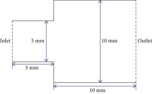
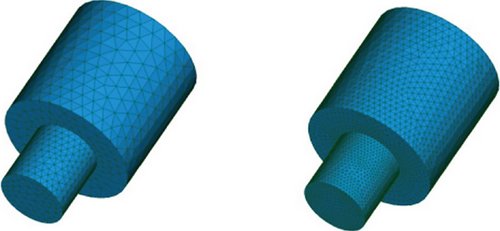
As shown in Figure 4, a model of two cylinders is used to simulate a plasma device. Five components—H2, H, metal atom X, , and H+—are injected. The initial number density of each neutral component is 2.5 × 10²¹ m−3, and that of each ion component is 5 × 10¹³ m−3. The total number density of neutral molecules is 7.5 × 10²¹ m−3, the total number density of ions is 1 × 10¹⁴ m−3, and the number density of electrons is 1 × 10¹⁴ m−3. The injection velocity of particle injection follows a Maxwell distribution, where the velocity of the flow is 10,000 m/s and the neutral temperature is 0.3 eV, whereas that of the ion components is 0.5 eV and that of the electrons is 5 eV. The wall temperature is 300 K.
The potential boundary condition is that the inlet is the potential reference plane. The potential gradient perpendicular to the surface is zero, except for the inlet. When particles go past the boundary, they are simply deleted, except electrons. The time steps of DSMC and PIC are 1 × 10⁻⁸ and 1.25 × 10⁻¹⁰ s, respectively; △t ≤ 0.1ωp [24] is employed in PIC, and the weight factors are 5 × 10⁸ and 1.5, respectively. The simulation time lasted 6 μs. Elastic collisions between charged ions and neutral molecules are considered in DSMC. Collisions between electrons and neutral molecules and collisions between electrons and ions are not considered.

The total number of DSMC grids is 295,294, and the total number of grid nodes is 52,368. The total number of PIC grid nodes is 386,245, and the total number of grids is 2,253,268, as shown in Figure 6. The number of simulated molecules is more than 150 million after 1200 PIC time steps. The simulation calls for the 384 process of four nodes on the Tianhe-2 supercomputer. The computation time costs from 240 to 360 h, according to the models.
3.2. Wall Boundary Conditions Based on Charge Conservation
In our study, chemical reactions will occur after H+ and interact with the wall, as shown in Table 1. Because electrons are adsorbed on the insulation wall, ions will react with the electrons on the insulation wall to form neutral molecules. Therefore, when an H+ or ion interacts with the insulation wall, the number of electrons adsorbed in the current wall grid will correspondingly decrease by one to ensure charge conservation. This is the wall boundary condition based on charge conservation.
The ρb is the charge density on the wall. At the same time, the gradient of the electric field perpendicular to the wall is zero.
3.3. Energy-Based Outlet Boundary Conditions
If the electron moves out of the boundary with Ke ≤ PE, it will be specularly reflected at the exit boundary; otherwise, it is considered that the electron has experienced potential field acceleration and will be deleted.
For the second aspect, according to the physical reality, the number of electrons moving out of the computational domain should obviously be greater than or equal to the number of ions. When a higher outlet energy standard is adopted and the electron temperature in the flow field has not risen, too many electrons may be specularly reflected, and the corresponding ions will have moved out of the computational domain. Therefore, the energy-based outlet boundary condition needs to monitor the number of electrons and ions at the exit and count those that have been deleted from the calculation domain. If the number of ions is greater than the number of electrons, the excess part will delete the electrons in the specular reflection reflux field in chronological order rather than directly deleting the electrons in their current grid. At the same time, this example considers secondary electron emission. Charges will continue to deposit on the wall, leading to the constant rise of the flow field potential. Although the secondary emission of “cold” electrons will reduce the electron temperature of the flow field, the local electron temperature of the flow field will continue to rise. If the temperature of a large area of electrons in the flow field has risen significantly, that is, the average electron energy represented by the outlet energy standard is exceeded. For example, if the electron temperature of injected electrons is 3 eV, the outlet speed standard is 3.2 × 10⁶m/s, which represents the average energy of electrons at 14.5 eV; thus, the current boundary conditions will cause a large number of electrons to escape, resulting in an “ion sink,” which requires adjustment. Under the calculation conditions in this paper, the outlet energy standard is not needed temporarily. Because there are many secondary “cold” electrons, the electron temperature in most areas will drop.
4. Numerical Simulation of Secondary Electron Emission Spectrum Model of Insulating Emission Wall Sheath
In this section, the BN SEC model is adopted. The emitted electrons are numerically simulated using different energy spectrum modes to show the space-time distribution and electric field structure of particles in different flow fields and to explain the interaction between the energy spectrum model, sheath potential distribution, and each component density.
- 1.
In the Mozorov model, the emission electron temperature Tsee conforms to a Maxwell distribution of half the mainstream electron temperature Te, Tsee = 0.5Te.
- 2.
In the Furman model, Tsee = 1/3Te.
- 3.
In the vertical model, the emitted electrons conform to the Maxwell distribution of 0.1Te in the direction perpendicular to the wall. Assuming the x-axis direction is perpendicular to the wall, Tsee,x = 0.1Te. Assuming that the remaining two directions conform to the Furman model, Tsee,y = 1/3Te and Tsee,z = 1/3Te.
- 4.
In the three-temperature model, the emitted electrons in the direction perpendicular to the wall conform to the Maxwell distribution of three temperatures. For a BN wall, the electron incident temperature is Te = 5eV, α1 = 0.0495, Tse1 = 0.1361, α2 = 0.26055, Tse2 = 1.127, α3 = 0.69, and Tse3 = 4.043 in Equation (8). The temperature of the current electron obeying the Maxwell distribution is determined according to the interval of a randomly generated number in the simulation, and it conforms to the Furman energy spectrum model in the other two directions.
Because the speed of electron motion is too fast, the computational domain of this paper is small, and the entire computational domain belongs to the sheath region; when the injection number density is 5 × 10⁸ m−3, λd is 5.25 × 10⁻⁴ m. The diameter of the small cylinder in this paper is about 10λd, and that of the large cylinder is 20λd.
4.1. Numerical Simulation Results and Analysis of SES Models
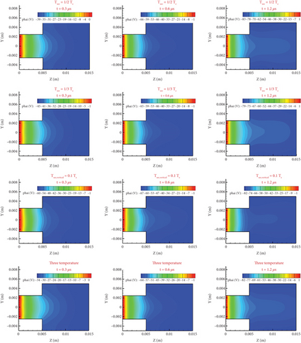
For the classical sheath of the steady flow of the plasma plume (i.e., the electric potential decreases monotonously in the direction pointing to the wall), the incidence of electrons on the wall follows a Maxwell distribution with a temperature of Te, and the change of the electron emission temperature on the wall in the steady-state sheath state has almost no effect on the electron density, electric potential, or electric field. Because in the steady-state sheath with a higher density in the mainstream (1018 m−3), the flow field can be divided into mainstream and sheath, and the sheath thickness is 10−6 m. The secondary electrons in the sheath quickly enter the mainstream, and it is difficult to affect the sheath itself. The emission temperature only affects the charge deposition. However, when all the calculation domain of this paper is sheath, the influence of SES models on the flow field is different from that of the steady-state sheath, which will have an important impact on the potential distribution and the electron and ion number density distribution in the sheath. As shown in Figure 7, there are obvious differences in the potential distributions of the models, but little difference after 1.2 μs.
In Figure 8, the specific lines z = 0.003 and z = 0.01 m in the middle of the small and large cylinders are intercepted to show the change in their potential distribution. The specific line z = 0.003 m indicates that the potential drop of the four models shows little change, but the absolute value of the potential is decreasing. Therefore, with the increase in time, the wall charges are depositing. Comparing line z = 0.003 m of the 0.6 and 1.2 μs curves of the same model, it can be seen that these curve morphologies have not changed greatly, and the main difference lies in the change of wall potential. The rate of change of the electric potential at the three different times is also different. The curve symmetry of each model changes at each of these three times, as seen in the Furman model’s 0.6 and 1.2 μs curves, which explains the dynamic deposition process of the wall potential. For the specific line z = 0.01 m, the change of potential drop is greater than the specific line z = 0.003 m in the small cylinder. Because electrons and ions are less in the big cylinder, the potential difference gradually increases.
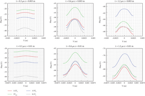
In general, the potential difference of the two specific lines is large at 0.3 μs, whereas that of each model becomes small at 0.6 and 1.2 μs. At 0.3 μs, the potential of the vertical model drops quickly to −60 V, whereas that of the other models changes slowly. From 0.6 to 1.2 μs, the difference in potential drop is small. Combined with the cloud chart shown in Figure 7, it is clear that the SES model mainly affects the intermediate process of reaching the stable flow structure, and the low emission temperature makes the flow reach the stable state more quickly.
When the number density of neutral molecules is far greater than that of charged particles, modeling the latter has little effect on the number density distribution of the former. Therefore, almost the same distribution figures of the three neutral molecules are not given.
Figure 9 gives the number density distribution of electrons in the x = 0 plane at 0.3, 0.6, and 1.2 μs. The cloud image shows that there are electron concentration and high-density areas on the small cylinder wall and the large cylinder wall, and there are also roughly two layers near the large cylinder wall. With the increase of time, the high-density area in the center of the small cylinder gradually disappears, whereas the high-density area on both sides gradually moves in the direction of the large cylinder. At the same time, the number density of electrons in the area near the walls of the large and small cylinders increases gradually.
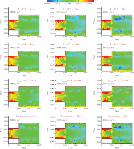
Over time, the density difference between the middle and the two sides will increase, so the characteristics of stratified flow will become more obvious. Because the reflected electrons are slower and the electrons near the central axis are faster, the density distribution of different models near the walls of the large and small cylinders is not completely the same. It can be seen that the vertical model has more electrons near the big cylinder than the other models; therefore, its emitted electrons are slower perpendicular to the wall and can remain in the flow field, which leads to its low potential difference.
From Figures 8 and 9, although the electron number density distribution in the x = 0 plane (in Figure 8) is not obviously symmetrical along the y = 0 axis, the potential distribution in the z = 0.003 or 0.01 m (in Figure 8) is almost symmetrical. The reason is that the electron number density distribution affects the ion number density distribution each other. If the electron number density is high in some areas, the ion number density is also high. We can find the characteristics from Figures 10, 11, 12, 13, 14, and 15 if we compare the number density of ions with the number density of electrons at the same point. The result is that the potential distribution is almost symmetrical.
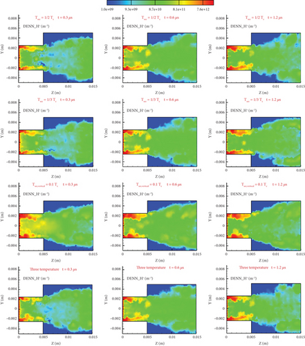

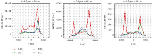

From Figures 16 and 17, it can be seen that on the whole, the distribution of electrons presents a situation of low intermediate number density and high number density near the wall. Under the current injection conditions, the thermal motion velocity of the electrons is between 1,000,000 and 3,000,000 m/s. When electrons interact with the wall, the velocity slows down by at least half. Therefore, the velocity difference between the wall electrons and those near the center that do not interact with the wall is very large. Because the electrons do not collide, the transport effect is not considered, and the axial electric field changes the fastest in the flow field. The difference between each model is the number density distribution gradient near the wall. As time increases, the number density near the wall increases. At 1.2 μs, the number density near the wall has accumulated more than that of 0.3 μs is an order of magnitude. The number density of the vertical model in the direction perpendicular to the wall is the smallest because its emission temperature is low, the average velocity of electrons perpendicular to the wall is low, and it is relatively easier for them to move to the exit, which is not conducive to accumulation near the wall. The absolute value of the distribution difference near the wall with z = 0.003 m is relatively small compared to the distribution with z = 0.01 m. Because the number of electrons moving from the entrance to the wall of the large cylinder is almost the same, the number density has decreased by nearly two orders of magnitude, and the impact of the emission temperature has also been reduced.
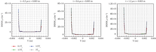
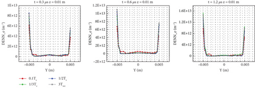
Comparing Figures 7, 9, and 10, it can be seen that the distribution of flow field potential basically corresponds to the distribution of high-density and low-density areas of electrons and ions. By comparing the four models in Figure 9, it is found that the electron number density distribution of the vertical model is greater than that of other models. However, its potential is not the lowest because the charge density distribution also depends on the number density distribution of ions near the wall. Because the emission temperature of the vertical model in the direction perpendicular to the wall is low, the electrons near the wall can constrain more ions. By comparison, the large cylinder vertical to the model has more areas of high ion density, so its potential is not much different from the other models.
From Figure 10, it can be seen that there is a high-density area near the walls of the large and small cylinders, as well as a low-density area near the central axis of the outlet of the large cylinder. As time increases, the small cylinder’s high-density area develops towards the outlet, whereas the large cylinder’s low-density area shrinks and the density gradually increases. Comparing Figure 9 with the distribution of the four models in Figure 10, it can be seen that the high number density area of electrons in the small cylinder basically coincides with that of H+. It can also be seen that the vertical and Furman models have relatively more particles on the wall of the small cylinder. Because the emission temperature of these two models is low and the electron velocity near the wall is relatively slow, there will be relatively more ions near the wall. In the large cylinder area, it can be seen that there is a high-density area of ions far away from the wall surface of the vertical model, whereas there are no high-density areas of other models, which also shows the influence of emission temperature.
From Figures 11 and 12, it can be seen that the distribution of the two specific lines shows that the number density is high near the wall and low in the middle. For the H+ number density distribution of specific line z = 0.003 m in the small cylinder, it can be seen that as time increases, the density on and near the wall of the specific line gradually increases, indicating the deposition of charges and the process of the high-density area moving towards the exit. Because the whole range of the big and small cylinders is in the sheath, there is a high-density area near the wall, which is different from the high-density area of the central axis. At 0.3 μs, the high-density area of the central axis only exists in the vertical model. This phenomenon reflects the role of the potential well-formed by electrons. As time increases, electrons deposit and recombine on the wall, leading to a change of ion number density near the wall and also leading to the incomplete symmetry of the number density distribution near the wall on both sides. Over time, the high-density area on both sides expands and gradually develops towards the center, whereas the low-density area near the central axis shrinks. The density near the central axis of the specific line z = 0.01 m in the large cylinder increases first and then decreases. Because the plume diffuses to the big cylinder, the speed increases, and the density decreases by two orders of magnitude. As the emission temperature of the vertical model is low, relatively fewer electrons escape from the outlet, so the electron number density of the model in the specific area of the big cylinder becomes relatively higher as time increases, which is also shown in Figure 17.
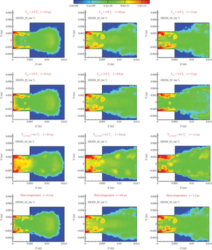
Figure 13 shows the distribution of number density in the x = 0 plane at three different times. Compared with H+, the structure of the whole flow field is similar, but the molecular weight of is large, and its diffusion ability is relatively weak. Therefore, the range of high-density area near the wall of the large cylinder is larger, and there are more ions in the central area of the vertical model. Figure 10 shows that electrons have a high number density near the wall of the large cylinder area. Therefore, after entering the large cylinder area, ions will move towards the walls on both sides, forming a high-density area, such as the distribution at 0.6 μs in Figure 13. As time increases, the high-density area near the wall gradually accumulates. The main difference between the four models is still reflected in the distribution of high-density areas near the wall in the small cylinder area, among which the high-density area of the vertical model is relatively large.
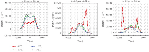
Comparing Figures 11 and 14, at the specific line z = 0.003 m, the number density of varies greatly, reflecting the transport characteristics that the diffusivity is weaker than that of H+. The variation range of number density at the specific line z = 0.01 m in Figure 15 is greater than that of H+, and the number density of the vertical model is always high, which is basically the same as the distribution change of H+. On the z = 0.003 m line at 1.2 μs, the differences between the four models are relatively small, especially in the high-density area, indicating that the influence of different electron emission temperatures is small. In particular, on the z = 0.01 m line at 1.2 μs, except for the high-density area of the vertical model, the distribution of the other models is basically the same.
5. Numerical Simulation of SEC Model of Insulating Emission Wall Sheath
In Section 4, the SEC is fixed. The fixed energy spectrum model in this section is the Furman energy spectrum model, and four different SEC models are used for the wall, including BN, Al2O3, C, and SiC. Through numerical simulation, the influence of SEC on the flow field potential and the distribution of each component density is analyzed.
5.1. Computational Models
When simulating secondary electron generation, after the electron interacts with the wall, the incident energy is used to calculate the corresponding event probability interval, and then the interval into which the random number falls is generated to determine the event that should occur. The velocity of the generated electrons is distributed according to the Furman model.
5.2. Numerical Simulation Results and Analysis of SEC Models
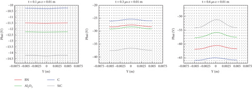
Because the temperature reduction along the computational domain is small, the average SECs of the four materials at 5 eV used for analysis can be calculated from Equations (1), (22), (23), and (24): BN is 0.53, Al2O3 is 0.59, C is 0.42, and SiC is 0.71, although the event of the single electron is affected by its incident energy and the SECs would fall along the computational domain. From the potential distribution cloud diagram of Figure 18, SEC has a great influence on the potential drop at different times.
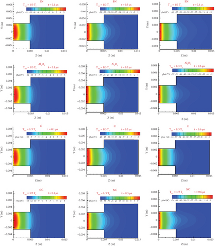
For BN and C (i.e., two materials with emission coefficients lower than 0.5), the potential field of the flow field is established slowly, and the potential gradually decreases, so the potential difference at three different times is large. In particular, when comparing the potential of C at 0.3 and 0.6 μs, the potential drops by about 39 V and for BN by about 34 V, whereas SiC (with a high SEC) drops by about 26 V and Al2O3 by about 28 V. The potential difference at 0.1 and 0.3 μs is about 17 V for C, 17 V for BN, 24 V for SiC, and 17 V for Al2O3. A wall with a high SEC generates more electrons, so the potential begins to decrease rapidly and then slowly.
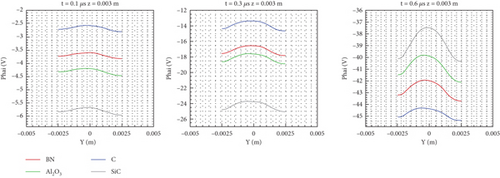
From Figures 19 and 20, at 0.1 μs, the total potential of the flow field decreases with the increase of the emission coefficient (e.g., the minimum potential of C is −10 V and that of SiC is −14 V). However, there are few charged particles in the flow field, so the difference caused by the emission coefficient is small. As time increases, at 0.3 μs, the specific linear electric potential in the big and small cylinders still decreases with increasing magnitude according to the emission coefficient. Thus, in the flow field at this time, because the wall material with a large SEC provides more electrons near the wall and fewer wall electrons are deposited, there are fewer ions that can be bound, so there is a large charge density gradient and a large self-consistent potential. As time increases, the ions gradually move to the boundary. At 0.6 μs, as the potential near the wall continues to increase, the number of electrons and ions near the central axis decreases, so the potential is opposite to that at 0.3 μs. The potential of C with a large SEC is high, whereas the potential of C with a small SEC is low.
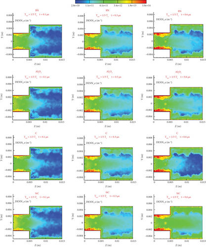
The electron number density distribution diagram of Figure 21 directly reflects the important influence of the emission coefficient on electron number density. This effect is mainly reflected in the medium-density areas, such as the entrance of the small cylinder and the wall of the large cylinder. Because the same energy spectrum model is used, the distribution of high-density areas near the small cylinder is similar. The difference in number density will be quantitatively analyzed at the specific line below, which is found to be small. Due to the difference in wall emission coefficient, the wall with a high SEC will produce more “slow” secondary electrons, which are slower than the mainstream high-speed electrons, so they will gather near the wall. In the small cylinder area, the electrons gather at the entrance and then move forward over time. The electrons in the large cylinder area mainly accumulate near the wall. At 0.6 μs, the various wall materials show relatively significant differences. SiC has a high number density in the above two areas, forming a relatively significant difference from other materials. At the same time, from Figure 20, it can be seen from the distribution cloud diagram at 0.6 μs that the distribution of the central axis area of the large cylinder is also related to SEC—the higher the coefficient, the greater the density, and the more particles there are. However, the difference of this region is only established in the flow field potential field, which is from 0.1 to 0.3 μs, and this difference is not significant, which indicates that the distribution of this area has a strong relationship with the structure of the potential field, and it is an indirect effect caused by different emission coefficients. Because there are many electrons near high-SEC walls, it is more difficult for continuously injected electrons to move to the wall, so the electron number density of high-SEC walls is high. The result is that the potential difference between the high-SEC central axis and the wall is larger, which corresponds to the conclusions drawn from Figures 19 and 20.
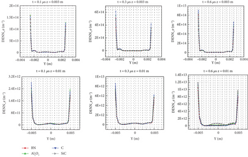
On the other hand, from Figure 22, it can be seen that for the electron number density distribution of a specific line before 0.6 μs, the electron number density distribution was similar, except at z = 0.01 m. The wall charge deposition is inversely proportional to SEC, and the wall charge deposition of C at both specific lines is higher. However, after the further development of the flow field, at 0.6 μs, the difference between the charge densities of the two specific lines and the four materials decreases, whereas the regional difference, except for the wall at z = 0.01 m, increases, and the number of electrons in the large cylinder region of high-SEC materials significantly increases. In general, the difference in electron number density is mainly reflected in magnitude, whereas the overall distribution is not very different, which is similar to the conclusion obtained by the SES model.
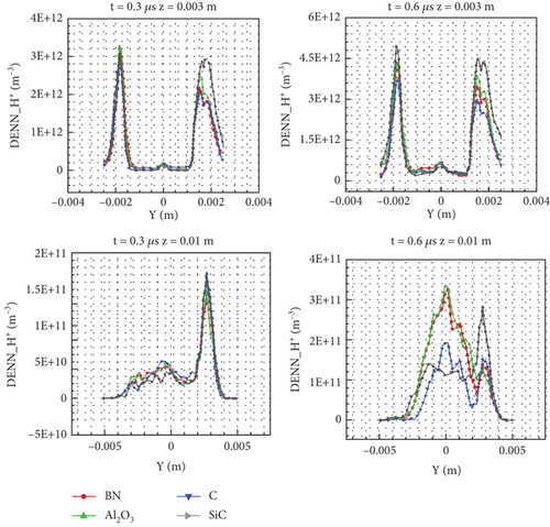
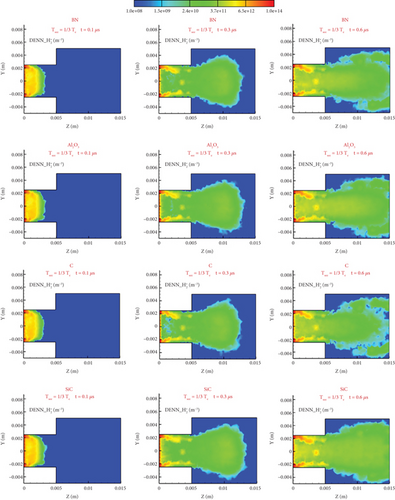
The H+ number density distribution in Figure 23 shows the influence of the emission coefficient. First, in the early stage of flow, there are fewer electrons and ions in the flow field. Therefore, at 0.1 μs, there is no significant difference in flow structure and distribution. As the thermal motion speed of an electron is large, upon comparing the electron number density distribution at 0.1 μs in Figure 21 with that of Figure 23, the electron has moved out of the calculation domain, and the high-density region is still in the small cylinder region. Then, after the ions enter the flow field, due to the large number of electrons at the rear of the flow field, the ions have an obvious acceleration effect along the axis, forming a high-density low-density high-density structure near the entrance.
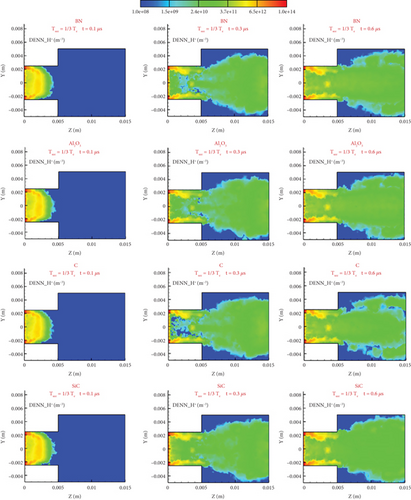
Comparing Figures 18 and 23, the potential field forms a positive potential zone at the entrance, as shown in Figure 23, indicating that the H+ and densities are relatively high at this time. As time increases, at 0.3 μs, as the ions move to the large cylinder area, this high and low high-density flow structure is destroyed, and the high-density area near the front end diffuses rapidly in the large cylinder area. Therefore, it can be seen that the whole flow field is obviously divided into two parts. One part is the broken annular zone, with part of the high-density area remaining inside the small cylinder, which is mainly near the wall and develops forward along the wall; the other part spreads from the small cylinder to the large cylinder. At this moment, comparisons of the distribution differences of the four wall materials reflect the influence of SEC. More secondary electrons enter the flow field, which will lead to more ions left in the flow field. Therefore, the interface between two parts of the wall with a high emission coefficient after the high-density area breaks is not obvious, such as the distribution of SiC. For low-SEC walls, there is a certain ion vacuum area, and the lower the SEC, the more obvious the effect, as shown in the distribution of C. Subsequently, ion movement will fill this area. At 0.6 μs, it can be seen that for BN and C, two large cylindrical areas on the wall (with average emission coefficients lower than 0.5) have formed two parts. Because of the conservation of mass, this internal vacuum area has developed to the periphery, forming two ion areas. When the emission coefficient increases, the boundary area of these two parts of the region is blurred (e.g., the difference can hardly be seen in SiC).
Figure 24 shows the distribution of two moments on a specific line of the large and small cylinders. On the line z = 0.003 m in the small cylinder area, the number density of SiC with a large SEC is highest, whereas that of C with the smallest SEC is lowest. Because materials with higher SECs have more electrons entering the flow field, their acceleration effect on ions will be stronger—more ions will gather in the high-density area at the entrance, and more electrons will be produced just near the wall. Therefore, the ion number density in the high-density area of the annulus near the wall formed later is higher. However, for the flow in a large cylinder, there is no significant difference between various materials on the specific line z = 0.01 m at 0.3 μs because the difference brought by the SEC is mainly concentrated in the high-density area near the wall. At 0.6 μs, it can be found that the density is positively related to the emission coefficient. The distribution of BN and Al2O3 is almost the same, and the distribution of C is the same, but the number density of central areas is only two-thirds of the others. The density distribution of SiC is different. The density is not relatively high in the central area, but it is higher near the wall.
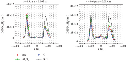
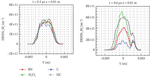
The number density distribution of in Figure 25 is similar to that of H+—the main difference lies in the molecular weight. Because the molecular weight of is twice that of H+, the electric field force on is reduced by half under the same field strength. At 0.1 μs, there is no obvious low-density area at the inlet center of , and its high-density area does not develop as rapidly as H+. At 0.3 μs, H+ has filled the whole flow field, whereas has not yet fully moved to the outlet boundary. At the same time, the transport capacity of is relatively weak, so the low-density area in the small cylinder is not as large as that of H+. Also, the transport capacity of is weaker than that of H+, so the low-density area in the small cylinder is not as large as that of H+. At 0.6 μs, C and BN (with lower SEC) are also obviously divided into two parts in the large cylinder. The main feature of C and BN is that there is a high number density area from the entrance to the center of the large cylinder, whereas H+ has no such feature. It can be seen that more is left in the flow field due to the heavier particles. Comparing the four wall materials at 0.6 μs, the difference in number density along the entire central axis area can be clearly observed from the cloud image. SiC (with high SEC) has a higher number density along the entire axis, and it develops to the entire flow in the large cylinder area, whereas that of C only exists in the small cylinder area. With the increase of the emission coefficient, the size of this area gradually increases (e.g., the area of Al2O3 is larger than that of BN). The distribution on a specific line is more helpful in distinguishing the difference caused by the emission coefficient.
It can be seen from the specific line z = 0.003 m in Figure 26 that the distribution characteristics are the same as those of H+, namely, lower in the middle and higher near the wall, but the number density of is 30% higher in most areas at both times, mainly because the increase of SiC is more obvious, whereas that of C is not increased in the whole area.
The distribution at the specific line z = 0.01 m in Figure 27 has no greater differentiation at 0.3 μs. Compared with H+, there is no higher number density area near the wall. The distribution is high in the middle and low on both sides. The main reason is that in the early stage of the flow development process, the high-density area in the small cylinder enters the large cylinder and diffuses differently. The distribution of H+ is relatively dispersed, whereas that of is relatively concentrated. The distribution of varies from a relatively small fraction at 0.3 μs to a relatively large fraction at 0.6 μs. The number density of C (with lower SEC) decreases, whereas the number density of SiC and Al2O3 (with higher SEC) increases, and that of BN does not change significantly. The maximum number density is found in Al2O3 rather than SiC, but the overall number density of SiC is high, and the area of high number density is wider, reflecting the characteristics of the high SEC. Al2O3 is unique in that it emits three electrons, thus binding more ions in a small range.
6. Conclusion
In this paper, wall boundary conditions based on charge conservation and energy-type outlet boundary conditions are studied. For the insulated emission wall, four kinds of energy spectrum models of secondary electron emission are used for numerical simulation. By comparing the Mozorov spectrum model, Furman spectrum model, vertical model, and three temperature model under the same SEC, it is found that if the secondary electron emission temperature is lower, there are more electrons and ions left in the flow field, and the potential changes are uneven due to the change of wall charge. The comparison of BN, Al2O3, SiC, and C wall materials under the same SES model shows that the lower the potential under a high SEC, the greater the electric field potential difference, and the higher the electron and ion number density. It is found that the influence of the SEC model on the flow field is greater than that of the energy spectrum model; for example, the variation of the potential and number density distribution is greater than 10%. The SEC model has an important influence on the potential of the flow field, the distribution of electron and ion number density, and the deposition of wall charges. There are many electrons and ions with a high emission coefficient but a low potential, which affects the whole flow process, whereas the SES model mainly affects the initial flow process. It should be noted that there is a need for more detailed analyses of the initial conditions, such as high number densities of both neutral particles and ions, different electron temperatures, and the coupling effect of additional models such as the charge exchange reaction in the sheath. Furthermore, the convergence study and analyses of the stability of the plasma plume would be our next work.
Conflicts of Interest
The authors declare no conflicts of interest.
Funding
This article is jointly funded by the National Natural Science Foundation of China and the China Academy of Engineering Physics (approval numbers U1730247 and 12372297).
Acknowledgments
This article is jointly funded by the National Natural Science Foundation of China and the China Academy of Engineering Physics (approval numbers U1730247 and 12372297).
Open Research
Data Availability Statement
All data included in this study are available upon request by contact with the corresponding author.


