Dynamic Dual-Level Overcurrent Protection Scheme for Distributed Energy Resource Networks Using Digital Twins Technology
Abstract
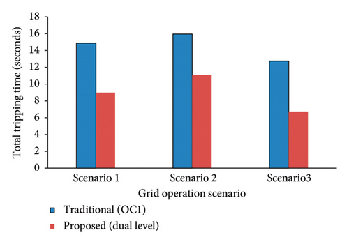
The integration of distributed generators (DGs), particularly renewable energy sources, into conventional distribution networks (DNs) presents significant protection challenges. This study introduces a novel digital twins-based overcurrent relay (OCR) protection scheme with dynamic dual-level characteristic curves for microgrids. By utilizing advanced technologies such as digital-twin technology and hardware-in-the-loop (HIL) testing, the proposed scheme enhances fault management and relay coordination. Key contributions of this work include the integration of advanced technologies and dynamic OCR settings, using digital-twin technology and HIL testing to provide real-time insights and robust validation under practical conditions. Additionally, the research thoroughly examines protection strategies for both grid-connected and islanded modes, ensuring reliable operation during faults or grid failures. The study’s findings show substantial improvements over traditional OCR methods. The traditional OCR recorded a total tripping time of 14.87 s, while the dual-level OCR reduced it to 8.97 s. The results highlight the proposed scheme’s enhanced sensitivity, faster fault isolation capability, and overall superior performance, providing a robust and reliable protection scheme for modern power distribution systems. Further testing results for the digital-twin OCR, comparing both the digital simulation twin relay and the physical twin relay for the traditional single-level OCR scheme and the proposed dual-level scheme, provide valuable insights into the performance and reliability of these protection strategies. The close alignment between the simulation and physical results highlights the robustness and precision of the dual-level scheme.
1. Introduction
The increasing integration of renewable and nonrenewable distributed generation (DG) within the frameworks of smart grids (SGs) and microgrids (MGs) has highlighted considerable attention in recent years [1]. Deploying DGs in SGs offers numerous benefits, including enhanced efficiency and reliability [2]. However, the incorporation of DGs into the conventional distribution network (DN) structure introduces complexities to the control and protection systems of SGs and MGs [3]. As a result, developing new protection schemes of SGs and MGs has become a significant focus in contemporary research [4, 5]. The evolving topology of power DN, which now include DG units and the islanding capabilities of MGs, has led to substantial changes in short-circuit current magnitudes and directions. These changes have impacted the reliability of protection systems, establishing as a loss of selectivity, sensitivity, and dynamic response [6]. Protection constraints are critical factors limiting the maximum penetration of DG in power systems. The integration of DGs changes the short-circuit level, potentially causing incorrect operation of protective relays and leading to protection mis-coordination [7]. Therefore, ongoing research aims to address these challenges, ensuring that the protection systems can adapt to the new dynamics introduced by DG integration and maintain the stability and reliability of the grid.
- •
Hardware-in-the-loop (HIL) Testing is crucial for validating protection schemes in realistic, controlled environments. However, most studies do not incorporate HIL testing, which limits the real-world applicability of their findings. The proposed approach addresses this gap by integrating HIL testing, thereby ensuring that the protection strategies are robust and reliable under practical conditions.
- •
Many studies have not utilized Digital-Twin Technology for dual level OCR protection scheme, which provides real-time insights and facilitates advanced predictive maintenance and optimization. This technology can significantly enhance the reliability of protection schemes in dynamic environments.
- •
Islanded Mode operation, which dramatically impacts protection strategies due to the absence of main grid support, has only been considered in a few studies, such as [15, 27]. The lack of focus on islanded mode in most studies represents a critical gap, as MGs frequently operate in islanded mode during faults or grid failures.
| Ref | Year | Characteristic curve type | Dual level protection scheme | Optimization algorithms | Different network configurations | HIL for dual level protection scheme | Islanded mode | Digital-twin for dual level protection scheme | |
|---|---|---|---|---|---|---|---|---|---|
| Standard | Nonstandard | ||||||||
| [12] | 2014 | ✓ | ✓ | ✗ | Karush–Kuhn–tucker | ✗ | ✗ | ✗ | ✗ |
| [13] | 2016 | ✓ | ✗ | ✓ | Nonlinear programs | ✓ | ✗ | ✗ | ✗ |
| [11] | 2017 | ✓ | ✓ | ✗ | ✗ | ✓ | ✗ | ✗ | ✗ |
| [14] | 2018 | ✓ | ✗ | ✓ | ✗ | ✓ | ✗ | ✗ | ✗ |
| [15] | 2018 | ✓ | ✓ | ✓ | Genetic algorithm | ✓ | ✗ | ✓ | ✗ |
| [16] | 2019 | ✓ | ✓ | ✗ | Genetic algorithm | ✓ | ✗ | ✗ | ✗ |
| [17] | 2019 | ✓ | ✗ | ✓ | Firefly algorithm | ✗ | ✗ | ✗ | ✗ |
| [18] | 2019 | ✓ | ✗ | ✓ | Genetic algorithm | ✗ | ✗ | ✗ | ✗ |
| [19] | 2020 | ✓ | ✓ | ✓ |
|
✓ | ✗ | ✗ | ✗ |
| [20] | 2020 | ✓ | ✓ | ✓ | Differential evolutionary | ✓ | ✗ | ✗ | ✗ |
| [21] | 2021 | ✓ | ✓ | ✓ |
|
✓ | ✗ | ✗ | ✗ |
| [22] | 2021 | ✓ | ✓ | ✓ |
|
✓ | ✗ | ✗ | ✗ |
| [23] | 2022 | ✓ | ✗ | ✓ | ✗ | ✓ | ✗ | ✗ | ✗ |
| [24] | 2022 | ✓ | ✓ | ✗ | ✗ | ✓ | ✗ | ✗ | ✗ |
| [25] | 2022 | ✓ | ✓ | ✓ | ✓ | ✓ | ✗ | ✗ | ✗ |
| [26] | 2022 | ✓ | ✗ | ✓ | Genetic algorithm | ✓ | ✗ | ✗ | ✗ |
| [27] | 2022 | ✓ | ✗ | ✓ |
|
✓ | ✗ | ✗ | ✗ |
| [28] | 2023 | ✓ | ✗ | ✗ | ✗ | ✓ | ✗ | ✗ | ✗ |
| [29] | 2023 | ✓ | ✓ | ✗ | Hybrid GA-NLP algorithm | ✓ | ✗ | ✗ | ✗ |
| [30] | 2023 | ✓ | ✓ | ✗ | Nonlinear program | ✓ | ✗ | ✗ | ✗ |
| [31] | 2024 | ✓ | ✗ | ✓ | Genetic algorithm | ✓ | ✗ | ✗ | ✗ |
| [32] | 2024 | ✓ | ✗ | ✓ |
|
✓ | ✗ | ✓ | ✗ |
| Proposed approach | ✓ | ✗ | ✓ | Water cycle | ✓ | ✓ | ✓ | ✓ | |
- •
Integration of Advanced Technologies and Dynamic Settings: The study incorporates digital-twin technology and extensive HIL testing to provide real-time insights, predictive maintenance, and robust validation under practical conditions. Additionally, it uses CFCs in digital relays to dynamically adjust settings based on the current level, optimizing performance under varying fault conditions.
- •
Comprehensive Analysis of Operating Modes and Network Configurations: This research thoroughly examines protection strategies for both grid-connected and islanded modes, addressing a critical gap by ensuring reliable operation during faults or grid failures. It also considers different network configurations, enhancing the adaptability and robustness of the proposed dynamic protection schemes.
These contributions collectively advance the state of the art in MG protection, addressing several critical gaps in the current literature and providing a robust, adaptable, and reliable protection scheme for modern power distribution systems. This article is structured as follows: Section 2 introduces the problem description for mitigation of high tripping times and mis-coordination in OCR for DN with DER which is referred to the failure of protection relays to operate in the correct sequence or timeframe, leading to power protection issues such as unnecessary tripping, delayed isolation, or failure to isolate faults. Sections 3 details the methodology of the innovative dynamic protection schemes using dual-level characteristics with digital twin strategy for enhanced OCR in DNs. Section 4 presents the findings of the proposed dynamic OCR scheme and HIL test results. Section 5 presents the conclusions and recommendations of this work.
2. Problem Description: Mitigation of High Tripping Times and Mis-Coordination in OCR for DN With DER
In the planning and coordination of OCRs, achieving proper coordination between primary and backup relays is crucial for ensuring efficient fault tripping. Primary OCR must quickly isolate faults on their designated lines. In contrast, backup relays address faults on subsequent lines, necessitating a coordinated delay to provide the primary relay sufficient time to operate. This coordination is particularly challenging in DN characterized by consecutive lines and parallel configurations. The integration of DERs further complicates the situation, as their varying contributions during faults affect OCR coordination. The following section illustrates the issues of high tripping times and mis-coordination in such networks.
2.1. High Tripping Time and the Impact of Consecutive Lines
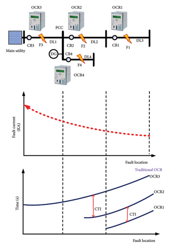
Consider a DN with power lines fed by a utility main source and a PV power plant, as illustrated in Figure 1. Coordinating OCRs OCR1, OCR2, and OCR3 on lines DL1, DL2, and DL3 involves setting the minimum tripping time for OCR1 as primary protection for fault F1. Subsequently, OCR2 is assigned a coordinated tripping time to serve as backup protection, isolating fault F1 on DL2. This practice ensures the quick isolation of fault F1, thus preventing damage from arc flash and thermal capability effects. However, when OCR2 operates as a primary protection for fault F2 on DL2, its tripping time is extended due to prior coordination with OCR1. This delay is notable even though fault F2, being closer to the network’s main sources, has a higher fault value than F1. The increased tripping time of OCR2 arises from the traditional use of single-level characteristics in the OCR for both primary and backup protection roles. This issue is magnified in networks with multiple consecutive lines, leading to extended tripping times for traditional relays nearer to the main sources, as shown in Figure 1. The presence of DER with high short-circuit contributions further exacerbates the issue, intensifying the impact of extended tripping times on network equipment’s arcing flash and thermal capabilities. This recurring problem highlights the necessity for advanced relay coordination strategies. For instance, in Figure 1, OCR3’s tripping time for fault F3 can exceed one second due to its coordination with OCR2 and OCR1, demonstrating the limitations of traditional single-level characteristics. Adopting digital relays with adaptable characteristics in modern DNs can mitigate these coordination issues, reducing tripping times and enhancing protection reliability.
2.2. Mis-Coordination and Challenges in Parallel Distribution Lines
Coordinating parallel distribution lines, particularly those with significant differences in the number of bus stations, presents additional complexities. For example, in Figure 1, coordinating OCR4 and OCR3 as primary and backup protection for lines DL1 and DL4 is challenging. Typically, OCR3 is coordinated more closely with OCR2 on DL2 to avoid nonselective tripping for faults on lines DL2 and DL3. This approach, however, complicates achieving adequate coordination time for OCR3 with OCR4 for faults on DL4. Should OCR4 fail to operate, OCR3 must serve as secondary protection. Yet, due to its prior coordination with OCR2 and OCR1 on the first line, OCR3 may not provide adequate secondary protection for faults on DL4. This mis-coordination is particularly significant when DGs are present on DL4, increasing the delay in fault current tripping time and adversely affecting the equipment’s arcing flash and thermal capabilities. In order to address these challenges, it is essential to utilize digital relays with adjustable and controllable features. Implementing dual-level characteristics for complex networks with substantial input from distributed energy sources can effectively resolve these coordination issues. This strategy will improve the security and reliability of protection schemes in contemporary distribution networks.
3. Innovative Dynamic Protection Schemes Using Dual-Level Characteristics With Digital Twins Strategies for Enhanced OCR in DNs
Adopting innovative digital relays with advanced features is essential to address the challenges in OCRs coordination. These digital relays offer CFCs that allow dynamic adjustments based on real-time conditions, significantly improving fault detection and clearance times. Employing digital twin technology, such as extensive HIL testing, is crucial for validating new protection schemes and ensuring their practicality and robustness.
3.1. Framework for the Proposed Dual-Level Advanced Protection Strategy
Developing a framework for implementing these advanced protection strategies enables operators to enhance MG protection systems, optimizing the protection scheme for modern DN with distributed energy sources. Upgrading adaptable relay characteristics and performing stringent testing can improve power distribution systems′ reliability, safety, and resilience. The dual-level characteristic proposed in this study aims to improve the coordination process of OCR performance. It achieves this by decreasing the operating time of OCRs when they function as primary protection while also ensuring appropriate coordination time with adjacent relays when operating as secondary protection. The integration of PV power into DN plays a significant role in improving system performance by reducing losses and emissions. Additionally, PV contributes to the generation mix, allowing a share of the system’s energy demand to be met through clean and renewable sources. However, the inclusion of PV systems introduces challenges for conventional protection devices, as traditional schemes often fail to address the complexities of networks with distributed PV generation, as shown in Figure 2(a). This can result in reduced reliability and stability of the electrical grid. In this study, the proposed dual-level approach effectively addresses issue such as time delays and mis-coordination caused by PV integration. In traditional OCR approaches, as shown in Figure 2(a), with one scheme, when OC1 operates as a primary protection for faults, its tripping time is extended due to prior coordination and it faces challenges with adding DGs. As illustrated in Figure 2, the dual-level characteristics consist of two regions: OC1 and OC2. These regions enhance the functionality of OCRs in different fault scenarios. The first region, OC1 operates as protection for low-value faults, ensuring appropriate coordination. The second region, OC2, serves as a primary protection for high-value faults, providing a quicker tripping time than traditional single-level characteristics.
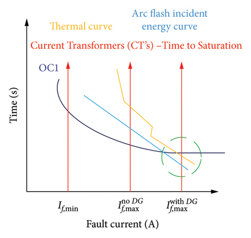
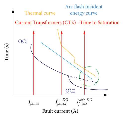
Comparing the conventional single-level characteristics, as shown in Figure 2(a), with dual-level characteristics, Figure 2(b) the proposed dual-level approach significantly enhances the reliability and safety of the protection scheme. For example, in the event of a fault on the first line DL3, OCR1 will operate in the first region OC2, providing secondary protection, OCR2, with appropriate coordination time. Conversely, for a fault on the second line DL2, the second region OC2 will ensure a quicker tripping time, improving the response compared to traditional single-level characteristics, as shown by the dotted line in Figure 2(b). Incorporating the second region in the dual-level characteristics results in faster tripping times for OCR2 when it operates as a primary protection for faults such as F2, reducing arc flash and thermal stress on equipment. This improvement is illustrated in the green region of Figure 2. Additionally, the dual-level selectivity and coordination enhance the performance of OCRs in parallel line configurations. The reduced tripping time in OCR3, when coordinated with OCR2 and OCR1, improves its coordination with OCR4 during faults on line DL4.
3.2. Dynamic Dual Level OCR Scheme
The proposed dynamic OCR protection system improves the protection system’s capability to manage the different power network topology and configurations. This research focuses on the development and evaluation of new dynamic dual level OCR protection systems. The proposed dynamic OCR schemes adjust the relay settings based on the network topology. This includes power networks with and without PVs and islanding modes. The status of circuit breakers and grid information is first analyzed to determine the network topology, identifying whether the system is operating in grid-connected mode or islanding mode. The current state of the network topology is then compared to its previous configuration. If the topology remains unchanged, the previously saved settings are applied. This methodology ensures that the protection system remains optimized for the existing configuration, thereby enhancing its reliability and responsiveness to fault conditions. The optimal group settings for the dual level OCRs scheme are then selected and implemented through communication links. This research employs three distinct group settings in addition to the dual level setting, detailed in Table 2, to enhance the sensitivity and selectivity of OCRs. For practical implementation, the proposed approach necessitates that OCRs allow for automatic real-time modifications to their settings. In general, dynamic dual setting relays are often believed to require communication links for coordination between different group protection settings. However, in our proposed system, there is no need for communication links for the dual setting. One of the key advantages of this approach is that we implement the dual-level functionality within modern OCR (digital relays) for each group of setting. Specifically, we integrated this adjustment directly into the 7SJ632 relay, allowing it to switch between levels based on the fault current level without requiring external communication links. This simplifies the system and improves reliability, as there is no dependency on communication infrastructure.
| Group settings | Status of circuit breakers | |
|---|---|---|
| Utility power source | PV power source | |
| Power network with PV | ✓ | ✓ |
| Power network without PV | ✓ | ✗ |
| Islanding | ✗ | ✓ |
3.3. Validation and Practical Implementation of Digital Twins-Based OCR Protection Scheme
The proposed dual-level characteristics were validated using digital twin technology, confirming their effectiveness and reliability. The unique features and advantages of digital relays, such as Dynamic Relay Settings via CFCs, enable the dynamic adjustment of relay settings based on network configuration. This strategy optimizes OCR performance under varying fault conditions, addresses mis-coordination issues, and improves fault detection and clearance times. By configuring and manipulating relay characteristics within digital relays, the operation of OCRs in the presence of distributed sources is significantly improved, enhancing the reliability and selectivity of overcurrent protection schemes.
The CFC feature is utilized to identify group setting level in the dual level scheme, the relay logic transitions from OC1 to OC2 settings. This adjustment ensures that the OCR operates with a characteristic specifically designed for high or low fault detection and coordination. To validate the feasibility and effectiveness of this approach, the CFC functionality in the digital relay was employed to implement the modified characteristics within a digital twin, as shown in Figure 3. This testing environment provides a realistic and controlled platform for assessing the relay’s performance under simulated fault conditions, thereby ensuring the practical applicability and robustness of the proposed strategy. The optimal setting of OCRs is determined by using ETAP software and the available OCR within it (OCR digital), as shown in Figure 3(a). Then, the Digsi Software is used to build these setting and applied them on the real physical OCR (the SIPROTEC 7SJ631 Multi-function Protection Relay). ETAP and Digsi software were specifically chosen for this study due to their complementary capabilities in achieving the research digital twin objectives. ETAP is a highly regarded tool in industrial applications for power network analysis and was used to simulate the power network and conduct short-circuit studies to determine fault currents. These fault currents were essential for establishing coordination among protection devices. Additionally, ETAP facilitated the creation of digital twins for the power system, which were crucial for accurately modeling and analyzing system behavior. It also enabled the injection of fault currents into protection devices through OMICRON CMC 365 test equipment, which interfaced with Siemens protection relays. On the other hand, DIGSI software was indispensable for configuring and operating Siemens relays. It allowed for precise adjustment of relay settings and provided tools for analyzing faults and events recorded by the relays. The integration of ETAP for network simulation and fault analysis with DIGSI for relay configuration and diagnostics ensured a robust framework for achieving accurate relay coordination and in-depth fault evaluation in the study.
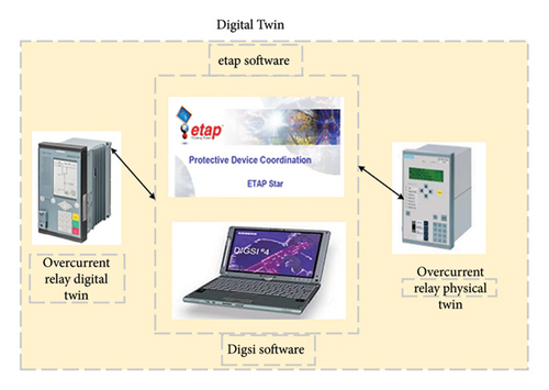
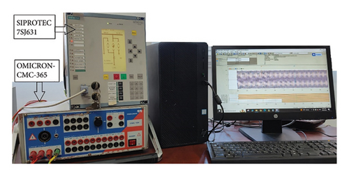
A real-time simulation platform is utilized to execute simulation models and synchronize them with hardware components for thorough digital twin testing. HIL testing significantly enhances the reliability of the proposed OCR scheme in several key ways. First, it allows for real-time simulation of the OCR scheme under various fault conditions and operational scenarios, enabling observation of how the relay responds to different inputs. This ensures that the proposed scheme operates effectively. Additionally, HIL testing validates the algorithms implemented in the OCR and helps identify potential weaknesses or failure modes in the proposed OCR scheme early in the development process. Furthermore, HIL testing evaluates how the proposed OCR scheme integrates with existing systems and devices, ensuring compatibility and effective coordination within actual grid environments. Finally, it creates a feedback loop where results from testing inform further refinements to the OCR scheme, enhancing overall reliability and performance. In this study, the HIL testing methodology is employed to validate the proposed dual level of OCR schemes in real-time scenarios. This validation process involves real-time testing using the OMICRON-256 on the SIPROTEC-7SJ631 Multifunction Protection Relay, confirming the effectiveness of the proposed OCR scheme. The OMICRON Test Universe software is used to control, validate, and record data from the OMICRON-CMC-365 equipment. The HIL testing setup includes physical hardware components such as the OCR (SIPROTEC 7SJ631) and the OMICRON-CMC-365 power testing equipment, as shown in Figure 3(b). Furthermore, a real-time simulation platform ensures synchronization with hardware components, enabling accurate and reliable performance evaluation.
4. Simulation Results and Discussion
This section assesses the performance of the proposed digital twins-based OCR scheme with dual levels of settings. Initially, the scheme’s effectiveness is evaluated using a CIGRI bus network, under various fault scenarios. The results of these tests are compared with the conventional approach, focusing on total tripping time and Coordination Time Interval (CTI). Furthermore, the proposed OCR scheme experiences validation through HIL testing, ensuring its performance and functionality in real-world conditions.
4.1. CIGRE Grid Model
- •
Scenario 1: CIGRE grid with PVs.
- •
Scenario 2: CIGRE grid without PVs.
- •
Scenario 3: CIGRE grid in islanding mode.
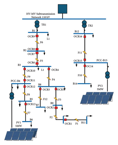
| OCR | CTR | Pickup current (Ip) | |||
|---|---|---|---|---|---|
| Traditional OCR and Level 1 (OC1) | Scenario 1 Proposed (dual-level) Level 2 (OC2) |
Scenario 2 Proposed (dual-level) Level 2 (OC2) |
Scenario 3 Proposed (dual-level) Level 2 (OC2) |
||
| OCR1 | 100/1 | 100 | — | — | — |
| OCR2 | 100/1 | 100 | 700 | 600 | 450 |
| OCR3 | 100/1 | 100 | 900 | 800 | 520 |
| OCR4 | 100/1 | 100 | 1100 | 1000 | 570 |
| OCR5 | 50/1 | 100 | — | — | — |
| OCR6 | 100/1 | 100 | 235 | 235 | 250 |
| OCR7 | 200/1 | 200 | 1200 | 1200 | 360 |
| OCR8 | 100/1 | 100 | — | — | — |
| OCR9 | 200/1 | 200 | 1600 | 1900 | 400 |
| OCR10 | 100/1 | 100 | 1000 | 1000 | 350 |
| OCR11 | 100/1 | 100 | 300 | 300 | 300 |
| OCR12 | 100/1 | 100 | 900 | 700 | 490 |
| OCR13 | 100/1 | 100 | — | — | — |
| OCR14 | 100/1 | 100 | — | — | — |
| OCR15 | 100/1 | 100 | — | — | |
| OCR16 | 100/1 | 100 | — | 2000 | 380 |
| OCR | TMS | |||||
|---|---|---|---|---|---|---|
| Scenario 1 | Scenario 2 | Scenario 3 | ||||
| Traditional OCR and level 1 (OC1) | Proposed (dual-level) Level 2 (OC2) |
Traditional OCR and level 1 (OC1) | Proposed (dual-level) Level 2 (OC2) |
Traditional OCR and level 1 (OC1) | Proposed (dual-level) Level 2 (OC2) |
|
| OCR1 | 0.01 | — | 0.01 | — | 0.01 | — |
| OCR2 | 0.12 | 0.01 | 0.09 | 0.01 | 0.12 | 0.01 |
| OCR3 | 0.22 | 0.01 | 0.21 | 0.01 | 0.195 | 0.01 |
| OCR4 | 0.33 | 0.01 | 0.31 | 0.01 | 0.27 | 0.01 |
| OCR5 | 0.01 | — | 0.01 | — | 0.01 | — |
| OCR6 | 0.05 | 0.01 | 0.05 | 0.01 | 0.048 | 0.01 |
| OCR7 | 0.3 | 0.01 | 0.3 | 0.01 | 0.125 | 0.01 |
| OCR8 | 0.01 | — | 0.01 | — | 0.01 | — |
| OCR9 | 0.16 | 0.01 | 0.39 | 0.05 | 0.07 | 0.01 |
| OCR10 | 0.19 | 0.01 | 0.2 | 0.01 | 0.11 | 0.01 |
| OCR11 | 0.11 | 0.01 | 0.11 | 0.01 | 0.095 | 0.01 |
| OCR12 | 0.11 | 0.01 | 0.1 | 0.01 | 0.08 | 0.01 |
| OCR13 | 0.01 | — | 0.01 | — | 0.01 | — |
| OCR14 | 0.01 | — | 0.01 | — | 0.01 | — |
| OCR15 | 0.05 | — | 0.01 | — | 0.01 | — |
| OCR16 | 0.14 | — | 0.14 | 0.01 | 0.066 | 0.01 |
4.2. CIGRE Grid Testing Results
4.2.1. Scenario 1: CIGRE Grid With PVs
In this section, the performance of the proposed dual-level OCR scheme is compared to the traditional OCR scheme under a grid interconnected to PV operation mode. The assessment focuses on the total tripping times for various fault locations, as shown in Table 5.
| Fault location | Fault current | Relay | Traditional (OC1) | Proposed (dual-level) |
|---|---|---|---|---|
| F1 | 764 | OCR1 | 0.169 | 0.169 |
| F1 | 764 | OCR2 | 0.405 | 0.405 |
| F2 | 905 | OCR2 | 0.373 | 0.271 |
| F2 | 905 | OCR3 | 0.684 | 0.59 |
| F3 | 1110 | OCR3 | 0.625 | 0.333 |
| F3 | 1110 | OCR4 | 0.937 | 0.625 |
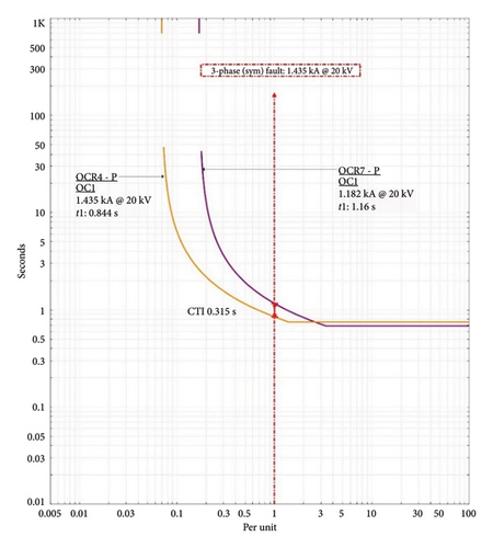
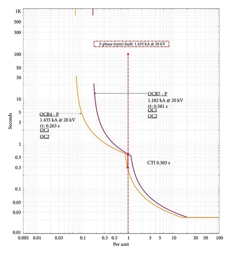
| F4 | 1435 | OCR4 | 0.844 | 0.263 |
| F4 | 1182 | OCR7 | 1.16 | 0.581 |
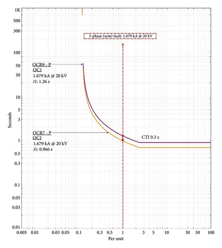
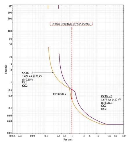
| F5 | 1679 | OCR7 | 0.966 | 0.208 |
| F5 | 1679 | OCR9 | 1.26 | 0.515 |
| F5 | 289 | OCR6 | 0.327 | 0.327 |
| F5 | 289 | OCR11 | 0.719 | 0.719 |
| F6 | 289 | OCR8 | 0.0653 | 0.0653 |
| F6 | 289 | OCR6 | 0.327 | 0.327 |
| F6 | 8820 | OCR9 | 0.884 | 0.0403 |
| F7 | 976 | OCR13 | 0.03 | 0.03 |
| F7 | 976 | OCR12 | 0.33 | 0.33 |
| F8 | 1176 | OCR12 | 0.305 | 0.261 |
| F8 | 946 | OCR10 | 0.609 | 0.579 |
| F9 | 1679 | OCR10 | 0.482 | 0.134 |
| F9 | 289 | OCR11 | 0.719 | 0.719 |
| F10 | 2327 | OCR14 | 0.022 | 0.022 |
| F10 | 2044 | OCR16 | 0.317 | 0.317 |
| F10 | 2327 | OCR14 | 0.022 | 0.022 |
| F11 | 289 | OCR15 | 0.327 | 0.327 |
| F11 | 8819 | OCR16 | 0.915 | 0.04 |
| F12 | 1116 | OCR5 | 0.113 | 0.113 |
| F12 | 1116 | OCR4 | 0.934 | 0.623 |
The results indicate that the proposed dual-level OCR scheme outperforms the traditional OCR scheme in reducing tripping times across various fault locations. At fault location F2, the dual-level scheme shows a noticeable improvement. OCR2’s tripping time decreases from 0.373 to 0.271 s, while OCR3’s tripping time is reduced from 0.684 to 0.59 s. This demonstrates the enhanced sensitivity and quicker response of the dual-level scheme at a fault current of 905A, indicating better fault detection and isolation capabilities. In addition, a significant performance enhancement is observed at fault location F3. The tripping time for OCR3 drops from 0.625 s (traditional) to 0.333 s with the dual-level scheme. Similarly, OCR4 shows a reduction from 0.937 to 0.625 s. These results highlight the dual-level scheme’s efficiency in handling higher fault currents (1110A), providing faster fault clearance and reducing the risk of equipment damage and service interruptions.
As shown in Figures 5 and 6, the proposed dual-level scheme demonstrates substantial improvements at fault location F4. The tripping time for OCR4 is dramatically reduced from 0.85 s (traditional) to 0.281 s. Across all fault locations, the dual-level OCR scheme consistently outperforms the traditional OCR scheme, particularly at higher fault currents. This improved performance is crucial for maintaining system stability and preventing extensive damage during severe fault conditions. The data indicate that the dual-level scheme provides superior fault detection and response times, ensuring better protection for the power DN.
4.2.2. Scenario 2: CIGRE Grid Without PVs
To assess the performance of the proposed dual-level OCR and traditional OCR schemes under grid powered only from the utility sources, Scenario 2, this section focuses on the total tripping times for various fault locations, as shown in Table 6. In all fault locations, the dual-level OCR scheme outperforms the traditional OCR scheme. The data clearly show that the dual-level scheme provides superior fault detection and response times. At fault location F11, the dual-level scheme shows an improvement. OCR16’s tripping time decreases from 0.317 to 0.161 s. In addition, as shown in Figures 7 and 8, the proposed dual-level scheme introduces a high level of improvements at fault location F5. The tripping time for OCR3 drops from 0.966 s (traditional) to 0.208 s with the dual-level scheme.
| Fault location | Fault current | Relay | Traditional (single level) | Proposed (dual-level) |
|---|---|---|---|---|
| F1 | 705 | OCR1 | 0.03 | 0.03 |
| F1 | 705 | OCR2 | 0.316 | 0.316 |
| F2 | 824 | OCR2 | 0.292 | 0.22 |
| F2 | 824 | OCR3 | 0.682 | 0.52 |
| F3 | 993 | OCR3 | 0.626 | 0.323 |
| F3 | 993 | OCR4 | 0.924 | 0.626 |
| F4 | 1248 | OCR4 | 0.838 | 0.315 |
| F4 | 1248 | OCR7 | 1.13 | 0.601 |
| F5 | 1679 | OCR7 | 0.966 | 0.208 |
| F5 | 1679 | OCR9 | 1.26 | 0.516 |
| F6 | 8475 | OCR9 | 1.06 | 0.0449 |
| F7 | 824 | OCR13 | 0.03 | 0.03 |
| F7 | 824 | OCR12 | 0.325 | 0.325 |
| F8 | 993 | OCR12 | 0.298 | 0.2 |
| F8 | 993 | OCR10 | 0.596 | 0.507 |
| F9 | 1248 | OCR10 | 0.541 | 0.315 |
| F9 | 1248 | OCR7 | 1.13 | 0.601 |
| F10 | 2136 | OCR14 | 0.022 | 0.022 |
| F10 | 2136 | OCR16 | 0.317 | 0.317 |
| F11 | 3083 | OCR16 | 0.317 | 0.161 |
| F12 | 993 | OCR5 | 0.114 | 0.114 |
| F12 | 993 | OCR4 | 0.924 | 0.626 |
4.2.3. Scenario 3: CIGRE Grid in Islanding Mode
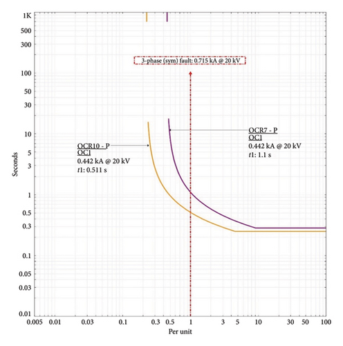
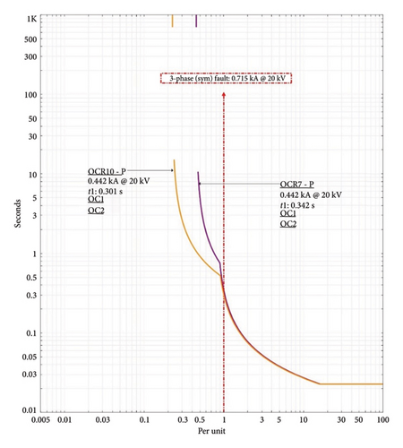
The performance evaluation of the traditional single-level OCR scheme and the proposed dual-level OCR scheme under various fault scenarios in an islanding mode is summarized in Table 7. The comparison provides insights into the effectiveness of the proposed approach in terms of tripping times for different fault locations and currents. At Fault Location F2, with a fault current of 556 A, the proposed dual-level OCR scheme reduces the tripping time for OCR2 from 0.481 to 0.329 s and for OCR3 from 0.782 to 0.621 s. This reduction demonstrates the dual-level scheme’s enhanced sensitivity and faster response. Similarly, the effectiveness of the proposed scheme is further evident at Fault Location F4, where the dual-level OCR scheme significantly decreases the tripping time for OCR4 from 0.981 to 0.466 s and for OCR7 from 1.3 to 0.77 s. The faster tripping times contribute to better fault management and improved system stability. At Fault Location F9, the dual-level scheme consistently shows faster tripping times for OCR10 (from 0.511 to 0.301 s) and OCR7 (from 1.1 to 0.342 s), as shown in Figures 9 and 10, indicating its superior performance in handling faults with varying current levels.
| Fault location | Fault current | Relay | Traditional (single Level) | Proposed (dual-level) |
|---|---|---|---|---|
| F1 | 505 | OCR1 | 0.213 | 0.213 |
| F1 | 505 | OCR2 | 0.511 | 0.511 |
| F2 | 556 | OCR2 | 0.481 | 0.329 |
| F2 | 556 | OCR3 | 0.782 | 0.621 |
| F3 | 613 | OCR3 | 0.74 | 0.426 |
| F3 | 613 | OCR4 | 1.02 | 0.721 |
| F4 | 662 | OCR4 | 0.981 | 0.466 |
| F4 | 390 | OCR7 | 1.3 | 0.77 |
| F5 | 289 | OCR6 | 0.314 | 0.294 |
| F5 | 289 | OCR11 | 0.621 | 0.719 |
| F5 | 442 | OCR7 | 1.1 | 0.342 |
| F5 | 442 | OCR9 | 1.4 | 0.658 |
| F6 | 289 | OCR8 | 0.0653 | 0.0653 |
| F6 | 289 | OCR6 | 0.314 | 0.294 |
| F6 | 498 | OCR9 | 0.532 | 0.317 |
| F7 | 590 | OCR13 | 0.0387 | 0.0387 |
| F7 | 590 | OCR12 | 0.31 | 0.31 |
| F8 | 635 | OCR12 | 0.297 | 0.27 |
| F8 | 361 | OCR10 | 0.592 | 0.565 |
| F9 | 442 | OCR10 | 0.511 | 0.301 |
| F9 | 442 | OCR7 | 1.1 | 0.342 |
| F9 | 289 | OCR11 | 0.621 | 0.719 |
| F10 | 708 | OCR14 | 0.0351 | 0.0351 |
| F10 | 436 | OCR16 | 0.309 | 0.309 |
| F11 | 498 | OCR16 | 0.283 | 0.257 |
| F11 | 289 | OCR15 | 0.327 | 0.327 |
| F12 | 613 | OCR5 | 0.136 | 0.136 |
| F12 | 613 | OCR4 | 1.02 | 0.721 |
Overall, the proposed dual-level OCR scheme shows significant reductions in tripping times across various fault locations and currents compared to the traditional single-level scheme. These improvements underscore the dual-level scheme’s potential to provide more sensitive and selective fault detection, thereby enhancing the protection and reliability of the power DN in islanding mode.
4.2.4. Comparison of the CIGRE Grid Testing Results
The comparison in Figure 11 presents the total tripping times for traditional OCR (OC1) and the proposed dual-level OCR schemes across the three different grid operation scenarios. The tripping times are recorded to evaluate the performance and efficiency of the proposed dual-level scheme in comparison to the traditional approach. In Scenario 1, the traditional OCR scheme records a total tripping time of 14.87 s, while the proposed dual-level OCR scheme significantly reduces the total tripping time to 8.97 s. These reductions of nearly 40% demonstrates the enhanced sensitivity and faster fault isolation capability of the dual-level scheme. The substantial improvement indicates that the dual-level approach is more efficient in detecting and responding to faults, minimizing the duration of disturbances and reducing the risk of prolonged faults which can lead to more severe damage to the power system. In Scenario 2, the total tripping time for the traditional OCR scheme is 15.95 s. The proposed dual-level scheme, however, reduces this time to 11.077 s. This reduction of about 31% highlights the dual-level scheme’s ability to adapt to varying fault conditions and network configurations more effectively than the traditional scheme. Scenario 3 shows the most improvement, with the traditional OCR scheme recording a total tripping time of 12.73 s, while the proposed dual-level scheme achieves a remarkably lower tripping time of 6.73 s. This reduction of approximately 47% is a clear indication of the dual-level scheme’s superior performance. The improved performance under different scenarios suggests that the dual-level OCR can handle more complex fault situations, ensuring better protection and stability of the power DN. These improvements are crucial for maintaining the reliability and stability of power DNs, especially in complex and dynamically changing environments.
4.2.5. Digital Twin OCR Testing Results
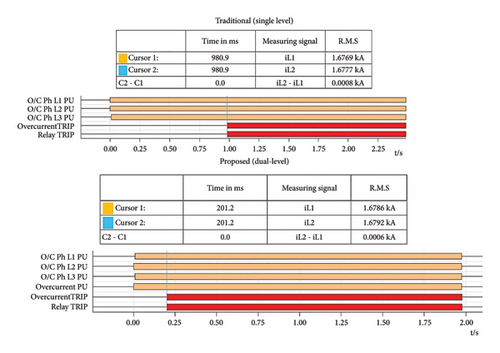
The testing results for the digital-twin OCR, comparing both the digital simulation twin relay and the physical twin relay for the traditional single-level OCR scheme and the proposed dual-level scheme, provide valuable insights into the performance and reliability of these protection strategies [35]. The comparison focuses on three fault locations (F4, F5, and F9) under different grid operation modes and evaluates the tripping times for both the simulation and experimental setups, as shown in Table 8. For fault location F4, the tripping times recorded for OCR4 and OCR7 show minimal differences between the simulation twin relay and the physical twin relay, indicating a high degree of accuracy and consistency between the simulated and experimental environments. The proposed dual-level scheme significantly outperforms the traditional single-level scheme, reducing the tripping time for OCR4 from 0.85 to 0.263 s and for OCR7 from 1.16 to 0.581 s. This performance enhancement is reflected in the physical relay tests, reinforcing the dual-level scheme’s effectiveness.
| Fault | Grid operation scenarios | OCR | Tripping time at simulation twin relay trip time | Tripping time at the physical twin relay experimentally | ||
|---|---|---|---|---|---|---|
| Traditional (single level) | Proposed (dual-level) | Traditional (single level) | Proposed (dual-level) | |||
| F4 | Scenario 1 | OCR4 | 0.844 | 0.263 | 0.852 | 0.263 |
| OCR7 | 1.16 | 0.581 | 1.17 | 0.581 | ||
| F5 | Scenario 2 | OCR7 | 0.966 | 0.208 | 0.980 | 0.201 |
| OCR9 | 1.26 | 0.516 | 1.27 | 0.521 | ||
| F9 | Scenario 3 | OCR10 | 0.511 | 0.301 | 0.532 | 0.301 |
| OCR7 | 1.1 | 0.342 | 1.14 | 0.342 | ||
At fault location F5, the tripping times for OCR7 and OCR9 also show minimal differences between the digital simulation and physical twin relays. The proposed dual-level scheme demonstrates substantial improvements over the traditional single-level scheme, reducing the tripping time for OCR7 from 0.966 to 0.208 s and for OCR9 from 1.26 to 0.51 s. The consistency between simulation and experimental results further validates the reliability of the dual-level scheme in real-world applications. The tripping times recorded for OCR10 and OCR7 at F9 exhibit slight variations between the simulation and physical twin relays, with the proposed dual-level scheme showing a notable reduction in tripping time. OCR10’s tripping time decreases from 0.511 to 0.301 s, and OCR7’s time reduces from 1.1 to 0.342 s. The close alignment between the simulation and physical results highlights the robustness and precision of the dual-level scheme.
Figure 12 illustrates an example of the experimental physical results at fault location F5 (OCR 7). The tripping times for OCR7 and OCR9 are detailed, showcasing the performance of both the traditional single-level scheme and the proposed dual-level scheme. For OCR7, the traditional scheme recorded a tripping time of 0.98 s, while the dual-level scheme significantly reduced this time to 0.201 s. Similarly, for OCR9, the traditional scheme’s tripping time was 1.27 s, compared to 0.521 s with the dual-level scheme. These results demonstrate the dual-level scheme’s enhanced sensitivity and faster response times, crucial for minimizing damage and maintaining system stability during fault conditions. The data from the experimental setup closely aligns with the simulation results, further validating the dual-level scheme’s effectiveness and practicality in operational environments. The comparison of digital simulation twin relay and physical twin relay testing results reveals that the proposed dual-level OCR scheme consistently outperforms the traditional single-level scheme across all evaluated fault locations. The dual-level scheme achieves significantly lower tripping times, enhancing the protection system’s responsiveness and reliability. The minimal differences between the simulation and experimental results validate the accuracy and practicality of the digital twin approach, confirming that the dual-level scheme can be effectively implemented in real-world scenarios to improve fault detection and isolation.
5. Conclusions and Recommendations
This study has introduced a novel digital twins-based OCR protection scheme with dynamic dual-level characteristic curves for MGs. The integration of digital-twin technology and HIL testing allows for real-time insights and robust validation under practical conditions, contributing to the scheme’s reliability and effectiveness. The research has thoroughly examined protection strategies for both grid-connected and islanded modes, demonstrating reliable operation during faults or grid failures. The comparison of the CIGRE grid testing results presents the total tripping times for traditional OCR (OC1) and the proposed dual-level OCR schemes across three different grid operation scenarios. In Scenario 1, the traditional OCR scheme recorded a total tripping time of 14.87 s, while the proposed dual-level OCR scheme significantly reduced the total tripping time to 8.97 s, demonstrating a reduction of nearly 40%. These improvements underscores the enhanced sensitivity and faster fault isolation capability of the dual-level scheme, minimizing the duration of disturbances and reducing the risk of prolonged faults that could lead to more severe damage to the power system. The close alignment between simulation and physical results highlights the robustness and precision of the dual-level scheme. For fault location F4, the tripping times recorded for OCR4 and OCR7 show minimal differences between the simulation twin relay and the physical twin relay, indicating a high degree of accuracy and consistency between the simulated and experimental environments. The minimal differences between the simulation and experimental results validate the accuracy and practicality of the digital twin approach, confirming that the dual-level scheme can be effectively implemented in real-world scenarios to improve fault detection and isolation. In conclusion, the proposed digital twins-based OCR protection scheme based on dual-levels of OCR settings represents a significant advancement in MG protection, addressing critical gaps in existing literature and providing a scalable solution for future power distribution systems.
Ethics Statement
The authors have nothing to report.
Disclosure
All persons who meet authorship criteria are listed as authors, and all authors certify that they have participated sufficiently in the work to take public responsibility for the content, including participation in the concept, design, analysis, writing, or revision of the manuscript. We also confirm that all authors have participated in drafting the article or revising it critically for important intellectual content; and approval of the final version.
No third-party services or individuals not listed as authors were involved in the research or manuscript preparation.
Conflicts of Interest
The authors declare no conflicts of interest.
Author Contributions
Conceptualization, F.A., H.Y.M. and N.E.-N.; methodology, N.E.-N., F.A., H.L., W.H. and A.S.S.; software, H.L., S.M.S., F.A., N.E.-N. and A.S.S.; validation all authors; formal analysis, F.A., W.H., N.E.-N., A.S.S. and H.L.; investigation, F.A., W.H., H.Y.M. and N.E.-N.; resources, all authors; data curation, all authors; writing—original draft preparation, F.A., H.Y.M. and N.E.-N.; writing—review and editing, all authors; visualization, all authors; supervision, all authors; project administration, H.L., A.S.S., F.A. and N.E.-N. All authors have read and agreed to the published version of the manuscript.
Funding
The authors extend their appreciation to the Deanship of Research and Graduate Studies at King Khalid University for funding this work through Large Research Project under grant number RGP2/238/45.
Acknowledgments
We would like to thank The Hashemite University (Renewable Energy Center) and the University of Salford for their support in publishing this article.
Open Research
Data Availability Statement
Derived data supporting the findings of this study are available from the corresponding author on request.


