Impedance-Based Adaptive Droop Control for Islanded AC Microgrids and Overview
Abstract
Recent improvements in the application of distributed energy resources (DERs) and microgrids (MGs) have made controlling these resources very important. However, there are still many challenges in this field. One of the anticipated challenges in islanded MGs (IMGs) is the mismatched output impedance of DERs, which affects the volt-var regulation, shortly after the occurrence of islanding mode. Ignoring these events creates consecutive power quality challenges such as circulating currents and reactive power sharing error, voltage variations, increased power loss, and overcurrent. Even though the microsources that make up the MG are located near loads, MGs often require receiving control commands from the central controller through low-/high-bandwidth communication networks to achieve the most stable operating point. Depending on the type of control structure, the information of the units including current, voltage, and active and reactive power is received/sent between one and three control levels. This paper aims to analyze the state-of-the-art techniques that are often developed based on adaptive virtual impedance droop control (AVIDC). Hierarchical structure and multiagent system (MAS) are the most coherent class of three-level infrastructures implemented by the consensus protocol. In this survey, the opportunities and threats of the islanded AC MGs controlled by the enhanced droop method using virtual impedance have been analyzed. At the same time, these have been implemented in centralized, decentralized, hierarchical, and MAS-based distributed coordination structures. Finally, the simulation results of an IMG controlled by AVIDC and based on line X/R ratio have been analyzed in PSIM Altair software.
1. Introduction
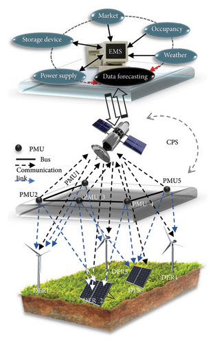
In the new generation of power systems, the ever-increasing aggregation of distributed energy resources (DERs) with traditional power systems results in improved power quality on the customer side. Intelligent strategies evolved with communication networks are needed to design a microgrid (MG) consisting of several DERs that inherently are heterogeneous [1, 2]. The multiobjective structure of communication network develops economical and comprehensive operations by converging all the components of MG to form a comprehensive smart grid (SG). It is realized according to complex intelligent algorithms, bidirectional communication links, and energy exchange, while control objectives have multiple time-scale characteristics. The SG processing is integrated with a physical cybersystem (CPS) that computes system parameters to enhance the security of communication infrastructure and realize a self-adjusting process. The CPS refers to engineered systems that have converged all the communication equipment and tools, self-monitoring and computing algorithms, and physical components, for the aim of data exchange through low-bandwidth communication (LBC) [3]. It is done in compliance with environmental compatibility and MG technical issues in real time [4]. Moreover, the acceptable flexibility and scalability are obtained by attribute-based encryption (ABE), which is widely used for data access control in SG. According to Figure 1, a wide-area measurement system (WAMS) is one of the data measurement patterns that employs phasor measurement units (PMUs) at each bus to estimate the magnitude and phase angle of time-varying voltage and current signals at the output of DERs [5] and then reflects an energy management system (EMS) to realize short-term/long-term predictions.
- •
Synergism between modern and traditional power systems to reduce mortality caused by greenhouse gases and global warming.
- •
Calculating the harmonic pollution tariff, using smart meters, income, and expenditure management on the customer side.
- •
Reducing the use of the transmission network and power loss, even in remote villages and impassable places [6–9].
- •
Participating in the energy market to improve power quality by heat and electricity generation and selling/buying surplus power to/from neighbors [7, 10–22].
- •
Reducing cost [23], outages arising from weakness of equipment, and increasing the reliability of power systems by localization of power supply [3, 24, 25], even though the communication link failures are lurking.
- •
Using islanding mode detection algorithms to isolate the damaged section until the system is restored [26].
- •
Eliminating circulating current [10, 27, 28], requiring spinning and nonspinning reserve [29], unbalancing active (P) and reactive (Q) powers [27, 28, 30–32], and improving harmonic power component sharing [33–39].
- •
Improving the trade-off between voltage–frequency drops in MG and reactive power sharing between units [10, 40–47].
- •
Automatic load shedding during system threats to minimize the length of time of outage and restoration [48].
- •
Guaranteeing a plug-and-play mechanism to calculate the average power between microsources [6, 24, 27, 36, 37, 49–52]. It means that DERs, battery energy storage systems (BESSs), and load components can be added/removed relative to/from the MG, while there is no interruption for system stability [11, 38, 53–55].
- •
Robustness to adding/removing one DER without affecting the control process of other devices that operate simultaneously [6, 10, 22, 23, 25, 36, 38, 39, 41, 56–76].
- •
Guaranteeing the fast dynamic response [6, 38, 67] and the stability of the closed-loop control system [21, 25, 77–79].
The SGs are able to operate in both grid-connected and off-grid modes as well as synchronize between the two mentioned operating modes [27, 80]. In connected mode, references of the voltage amplitude, frequency, current, and active and reactive powers at output of each DER are regulated by the commands received from central controllers. In off-grid mode, all the microsources are controlled by using information measurements of DERs at the point of common coupling (PCC), where the DERs are located in the closest place to the loads. The most important control principle in an islanded MG (IMG) is to regulate V and f in a steady state, while the accuracy of P/Q power sharing is maintained, regardless of what type of load characteristics it is.
2. Fundamental Concepts
In this section, the basic concepts to find the most accurate and fastest Q − V control in IMGs are explained.
2.1. Reactive Power Sharing Error
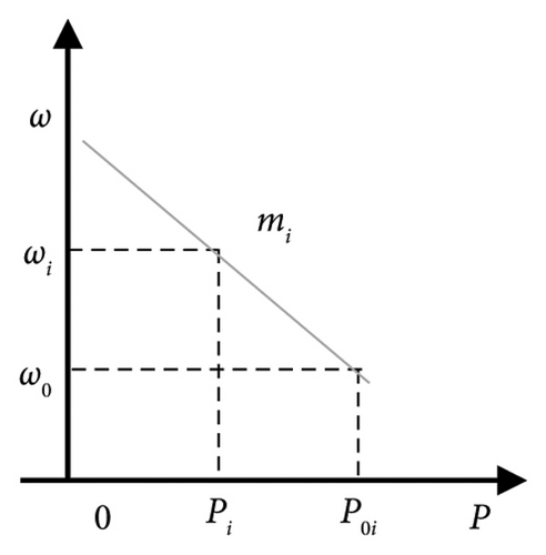
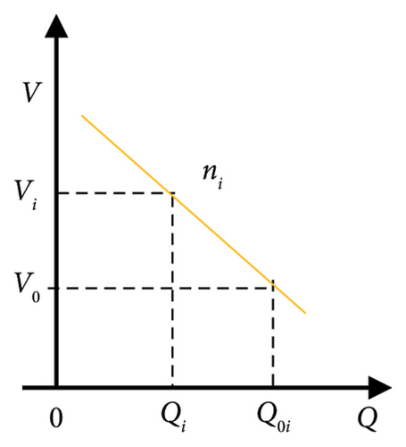
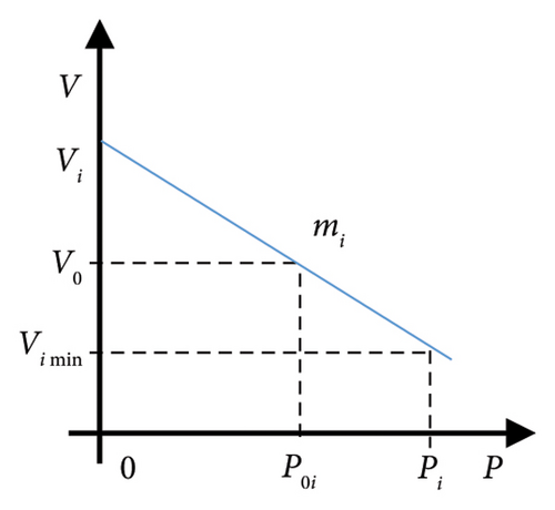
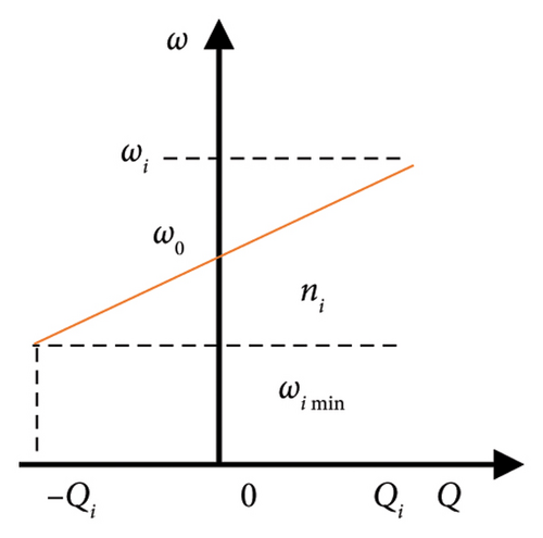
2.2. Adaptive Virtual Impedance Droop Control (AVIDC)
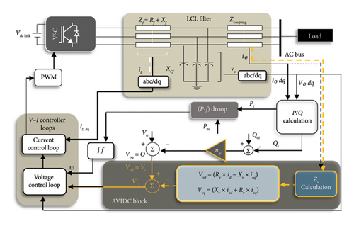
The adaptive ZV −-based controllers can be implemented without communication network [14, 62, 88–93, 106–111] or with communication infrastructure [4, 8, 13, 15, 16, 27, 41, 43, 44, 55, 61, 66, 94–100, 112]. In [101], a virtual impedance scheme is presented to control the virtual power supply, which consists of two parts: a negative resistance against line resistance along with P/Q power decoupling and a negative inductance to calculate accurate reactive power sharing by virtual voltage drop. In [103], an adaptive control technique is proposed for P/Q power sharing in a hybrid AC/DC MG equipped with a solar panel module/battery to support maximum reactive load demand. In [104], a reshaped MG is studied by an AVIDC approach, which is applied to grid-forming VSCs to rearrange units in the form of ideal AC voltage sources [103, 104].
3. Technical Implementation
The off-grid mode control can be divided into four categories according to the level of penetration of the communication network: (1) centralized control, (2) decentralized control, (3) hierarchical control by three levels of control, and (4) distributed coordination control. Scholars have tried to review the control of various aspects of SGs according to the four categories [2–4, 7, 10, 11, 53, 54, 70, 81, 102, 113–125]. Several papers have reviewed the IRPS from primary and secondary control outlooks to show the necessity of high controller levels for more accurate management of MG activities. In this way, hierarchical control has the largest number of research references, as the most well-known model [11, 53, 54, 70, 102, 113–115, 119, 122, 124, 125]. Another comprehensive control for the SGs is the distributed coordination control structure, which almost overlaps all the concepts of centralized, decentralized, and hierarchical structures. The concept of distributed control structure often refers to the configuration of multiagent systems (MASs) implemented by consensus protocols. This control manner is sometimes recognized in the form of hierarchical control in the literature [10, 53, 54, 70, 113–115, 117, 118, 120, 124, 125]. Although the MAS-based distributed coordination control has been reviewed in [10, 53, 70, 81, 113, 116–118, 124, 125], some of them have just defined the MAS-based distributed coordination control as in-text content, based on primary and secondary integrated levels [7, 10, 70, 118, 124, 125]. A few articles are supportive to adaptive control [3, 10, 11, 81, 102, 123, 125]. Furthermore, the close-loop adaptive control techniques have been reviewed based on the optimization of MG control by intelligent approaches in [3, 123]. However, the authors did not emphasize IRPS in [3]. In [102], although the AVIDC has been limitedly reviewed, it has not been focused on the MAS-based distributed coordination control.
The outlook of this paper is to theoretically study the challenges and opportunities of the inductive IMGs that are often managed by an AVIDC in the form of the quadruple control configurations. However, Q − V control of AC-IMGs by MAS-based distributed coordination control has been investigated in more detail than its other three counterparts. Prominent strains of MAS have been analyzed to determine how an IMG controlled by MAS can solve problems such as trade-offs between V − f regulation and IRPS, unwanted delays, and modeling complexity according to distributed averaging control, event-triggered control, and pinning-based control, respectively. Considering that the centralized, decentralized, and hierarchical structures based on primary and secondary levels have been sufficiently described in the literature, these have been reviewed with less analysis in this article.
3.1. Centralized Structure
Centralized control is known as the most traditional, most accessible, and most common control structure of power systems, which has highly accurate results due to the maximum reliance on the central controller. However, the centralized structure due to its reliance on both LBC and high-bandwidth communication (HBC) has the lowest security and reliability as it relies on the MG central controller (MGCC) as the mastermind of control. A centralized controller usually has a slower response time than a decentralized one like a droop controller. In such a controller, all the information related to the bus voltage, the frequency of the units, the P/Q output power, weather forecasting, etc., should be collected and sent to MGCC [61, 124, 125]. The MGCC is responsible for transferring and collecting information by an easy decision-making process [103]. This task is done by receiving commands from supervisory controllers, SCADA, and advanced data processing software such as advanced distribution automation (ADA) for controlling and monitoring purposes [126, 127]. The MGCC updates droop control parameters and gains every time interval (several minutes), quickly. After data aggregation from local controllers (LCs), the control pulses are synchronized using a phase-locked loop (PLL), and then, the current signal and V/f reference parameters are reflected in VSCs through HBC graphs [10, 41]. Common power regulators installed in each unit provide a global observation for precise tracking of the optimal set points and achieving cooperation between electronic-interface DERs [46]. Another advantage is interaction with demand-side management (DSM), which is based on end-user responses to balance supply and demand. In [14, 41, 61, 103, 128], the centralized-based AVIDCs are discussed according to arbitrary XV/RV ratios to control Q − V, while these are not required to use the communication between units; thus, it causes a decrease in delay. However, in [14], the IRPS is not compensated, accurately.
- •
Applicability is just for DERs connected to the common AC bus, in the form of small-scale MGs [13].
- •
Inefficient procedure for cost-effectiveness, reliability, flexibility and redundancy, and the plug-and-play mechanism (due to the requirement of a point-to-point connection between the central controller and all the units) due to relying on HBC and LBC [8, 39, 73, 80, 129–131].
- •
Dependency on computational databases and communication centers [105, 132].
- •
Risk of MG collapse after the occurrence of single-point outages in the communication network.
- •
Requirement for the circulating current sharing modules in both transient and steady states.
- •
Reducing the expandability of the system from a geographical point of view.
- •
Dependency on the knowledge of MG parameters including bus voltage, impedances, and load characteristics.
In the centralized structure, unlike the local one, the recalling information is transferred to the central controller, and conversely, the commands from the controller are transferred to sources through a communication link directly. As an example, a DER with the least changes is defined as the reference unit, and the output values of other DERs are compared to it to update by MGCC in real time. The updated values are then sent to all units to estimate the virtual impedance. Instead, in the centralized structure, the plug-and-play feature cannot be obtained because when a new source is added to MG, it is necessary to readjust the MGCC [14].
3.2. Decentralized Structure
This pattern is based on the allocation of V and f measurements in IMG upon predefined algorithms to solve the IRPS [133, 134], harmonic voltage distortion at the PCC, harmonic current/power sharing [135, 136], and V − f regulation just in a single-level structure. The decentralized control usually is applied to configure an MG with a large number of devices compared with the centralized structure [11, 18, 27, 29, 62, 70, 81, 90, 94, 102, 112, 113, 117, 118, 122, 124, 125, 137–146]. The decentralized control often is synonymous with the droop method, which is applicable just for off-grid mode. As the decentralized structure is inherently independent of the communication network, the advantages of the droop method such as reliability [10, 125], inviolability against delays, high-speed performance, cost-effective implementation, and the plug-and-play mechanism are often similar to the decentralized control features [70, 73]. However, for the same reason, it suffers from the IRPS, lack of flexibility, and diversity of the control system [7, 10, 11, 53, 54, 70, 86, 102, 113–120, 124, 125, 147]. These problems become more catastrophic when nonlinear load characteristics, harmonic power components, and voltage unbalance at the PCC are involved in the MG. [40, 72, 136]. In [29], a decentralized impedance-based droop method has been presented to reduce power loss. Nevertheless, the IRPS has not been analyzed, directly. In [142], a fully decentralized scheme is intended by using dead time to equalize the power coefficients in the LCs so that it leads to regulating the voltage drop affected by IRPS.
Some scholars believe that MGCC-based secondary control is another form of decentralized control, which is implemented according to a hierarchical structure [26, 53, 76, 82, 83, 149]. A lot of harmonic power sharing techniques [10, 13–20, 125], optimization issues (refer to Section 6), intelligent algorithms [94], etc., are often included in this category. For example, in [94], a fast servo system in decentralized control is presented to optimize voltage and the reactive power sharing by a fuzzy particle swarm method in off-grid mode.
The decentralized control structure is categorized into the following two groups.
3.2.1. Fully Decentralized Control Structure
This is a control structure with a low density among articles. In this model, microsources can control (Q − V) IMG with an independent control approach, without any communication link, even often without LBC. In this control structure, all the high-bandwidth control tasks, including conventional droop controllers and the virtual and adaptive impedance controller, are all done at the primary control level of each source using local measurements only, without the need for any information from other sources. Therefore, the best plug-and-play features can be obtained.
3.2.2. Pseudodecentralized Structure
It is another model of a decentralized structure that uses LBC to improve the control objectives of the IMG. As this control structure is often dependent on MGCC, it lacks some degree of independence and maybe the plug-and-play features. However, regarding the difference between these two decentralized control structures, in pseudodecentralized control, some challenges such as power sharing errors can be solved by relying on LBC while maintaining the reliability level of the IMG. In other words, the use of LBC should be such that the stability of the IMG does not depend on it.
3.3. Hierarchical Structure
The hierarchical pattern is usually identified by three control layers, which are organized according to ANSI/ISA-95 (International Automation Society). It is a management standard to recognize applicability between different organizations and control systems [53, 114, 143, 146, 150–154]. The important point during the hierarchical control process is to adopt a control approach with discrete-time scales to reduce delay and less complexity for data exchange. According to Figure 4, by adding each of the control layers, MG requires a communication graph implemented through a consensus protocol to exchange information (refer to subsection 3.4.2). Therefore, the hierarchical structure suffers from delay and sluggishness despite being accurate. Sometimes, the authors merge the secondary and tertiary control levels with the objective of reducing operating time [10, 149, 155, 156].
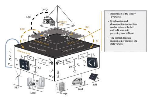
Features of the mentioned three levels are summarized as follows.
3.3.1. Primary Level
The measurement information at the primary level is sent to droop LCs for achieving P/Q power sharing, current control, and V − f regulation. Although this local control level has high-speed performance, it is not accurate enough [157]. The primary level usually tracks tasks of a decentralized structure so that it does not matter whether the control higher levels (secondary and tertiary) are in a centralized or hierarchical structure [24, 69, 96, 113, 158, 159]. The constituent elements of the primary level are specified at the lowest level in Figure 4.
3.3.2. Secondary Level
The primary level is independently sufficient for active power sharing; however, it may not be a guarantee for eliminating or mitigating the IRPS and V − f regulation problems for a lot of case studies (refer to Section 3). Therefore, the primary level sends output values of droop LCs to the secondary level through a bidirectional communication infrastructure. The new control level is developed by MGCC to improve power quality challenges [6, 70, 117, 160, 161]. The LCs regulate the dynamic response by tuning gains of AVIDC at the primary level based on reference signals received from the MGCC [9, 53, 86, 117] (see the middle level in Figure 4). The secondary level is more accurate, however slower than the primary level [52, 126, 162, 163].
- •
- •
Stabilizing power system based on the control of desired operating points [6, 72].
- •
Determination of P/Q power references to minimize voltage deviations, regulation of amplitude and angle of the output voltage at the PCC, improvement of IRPS, circulating current, and system synchronization [6, 21, 165, 166].
- •
Tackling power quality problems such as V − I control, nonlinear, and unbalanced load characteristics by calculating fundamental and high-order virtual negative/positive sequence [10, 13–20, 125].
3.3.3. Tertiary Level
This is an auxiliary layer located in the main grid for selling/buying power according to the electricity market constraints. The tertiary level optimizes the control system by following economic functions consisting of a distribution management system (DMS), a distribution network operator (DNO), and a market operator (MO) to manage the energy market [10, 152, 153] (see the highest level in Figure 4). The optimization command receives the economic and operational fee from the MO, DNO, and DMS and then transmits it to the secondary and primary levels. It is a long-term operation compared to the other two layers of control [160]. It is worth mentioning that the tertiary control level can just regulate the power flow in a steady state, so it does not guarantee V − f stability [149].
Several hierarchical control techniques have been presented in [17, 20, 34, 41, 48, 50, 55, 60, 66, 68, 72, 74, 85, 88, 94, 95, 112, 123, 146, 152, 154, 167–183]. These methods adjust the output power settings of individual VSCs according to logic controllers placed at the secondary level. In [13, 15, 18–20], the IRPS are illustrated by injecting a small harmonic signal, the type of quantity and frequency of which is determined by MGCC. However, these methods cannot guarantee system stability by relying on a classic event-triggered control. In [20], an active power small perturbations are injected to control the system for compensating IRPS, while the MGCC observes all exchanged signals and estimated parameters, for example, the output impedance of each DER. Simultaneously, a sluggish integration term is added to the conventional reactive power controller to eliminate the IRPS. In [72], a hierarchical control is presented to report IRPS by calculating the average value of reactive power so that the trade-offs between voltage regulation and reactive power sharing are guaranteed. Meanwhile, the plug-and-play mechanism is realized. In [24], a reactive power sharing algorithm can be implemented by following VSC parameters for the power self-adjusting process and for achieving maximum active power. However, both active and reactive power controllers must have access to the output reactive power information and the output voltage magnitudes of the DER. In [13, 15], the MGCC is responsible for the exchange of the harmonic voltage components with the common AC bus. This approach is a compensatory synchronization flag to LCs to improve the IRPS.
Certainly, the researchers attempt to find techniques that minimize challenges of delay, complexity, cyberattack threats, huge costs, etc., in a hierarchical structure as much as possible [116]. Thus, the SGs require a local control protocol that is intelligent and self-sufficient and does not rely on received commands from the central controllers for coordinating DERs and MG clusters.
3.4. Distributed Control
The idea of using distributed control in the form of SG was proposed in the mid-2000s for the first time [184]. Generally, all the control approaches of MGs are based on a distributed control paradigm until it is proven against this principle.
The hierarchical structure is an advanced configuration of decentralized control, so it can be expected that the hierarchical structure inherits the advantages of decentralized and even centralized control structures. Meanwhile, it has left behind a large part of their challenges [6, 23, 27, 38, 50, 53, 58, 64, 72, 73, 96–98, 154, 160, 163, 185–189]. In some reports, the authors believe that the distributed, decentralized, and hierarchical control are not different from each other [6, 23, 27, 30, 38, 39, 50, 58, 64, 72, 73, 97, 98, 134, 160, 163, 183, 185–193]. For example, in [190], the authors have preferred to introduce the two levels of control in a decentralized structure instead of defining it in an advanced hierarchical one. That is, in the fully distributed control, each controller requires just information exchange with its neighbors according to the bidirectional communication graphs without relying on a central controller [73]. However, sometimes unidirectional graph is implemented for the secondary controllers in distributed control form [185]. In [67], a robust nonlinear distributed approach is proposed to maintain the system stability and realize the P/Q power sharing with fast dynamic performance. In [111], an AVIDC is studied that synchronizes the output voltage of the DERs based on the difference between the output active power of each LC and the average active power signal to other LCs. In [73], a fully distributed control approach is presented that defines three control modules: (1) the voltage regulator, (2) the reactive power regulator, and (3) the (P − ω) regulator. The second module adjusts the (Q − V) droop coefficients to reduce the IRPS by considering the effect of the mismatched output impedance of units. Unlike most classic controllers, no frequency measurement is used in this AVIDC.
The examples mentioned are just a definition of conventional distributed control or hierarchical structure. Therefore, there are still fundamental problems such as delays, huge costs, complexity of control algorithms, and lack of trade-off between voltage regulation and reactive power sharing. Thus, advanced distributed coordination control is required.
3.4.1. Distributed Coordination Control Based on MAS
The most complex platform for SGs is the MAS-based distributed coordination control so that each DER and its internal LC act in the role of an intelligent agent [35, 57, 86, 105, 153, 186, 187, 194–196]. Global synchronization is the main control objective of agents preprogrammed in the artificial intelligence language. Agents are semiautonomous facts that exist in a software environment. Each agent can converge its conspecifics in a peer-to-peer model relative to itself through communication graphs [197]. It causes them to influence them in other environments and changes that environment according to a specific control motivation. The environment can be defined by tracking the conditions in which agents have the least penetration to change them. As agents are processed in an independent environment, these are self-sufficient factors to observe their performance [71]. Nevertheless, agents cannot be independent of their programming operator; therefore, these have just a significant degree of independence, which must be considered for a system and target [117]. In other words, each agent has a common target with other agents in a complex control system as an SG [197].
- 1.
Active agents (leader agents): It includes agents that are pinned in the control computation path as a dispatchable reference agent [39, 57, 99, 196].
- 2.
Reactive agents (passive/follower agents): It includes agents that are considered a nondispatchable obedient agent in the control computation path [39, 57, 99, 196].
- 3.
Complex agents (combination of 1 and 2) [39].
The leader–follower agents have a self-sufficient performance inspired by many control methods, which can control SG by time-varying communication infrastructure. The MAS-based distributed coordination control acts like a master–slave system for proper current sharing except that the master–slave control relies on the HBC link and receives commands from the central controller [26, 53, 76, 82, 83, 125, 198]. The MAS algorithms provide solutions for sending, receiving, analyzing, processing, accepting, and rejecting the information of other agents in a coordinated configuration [39]. In some papers, the MAS is introduced as a hierarchical or decentralized control frame [35, 57, 86, 96, 105, 113, 153, 186, 187, 195–199]. As the VSCs are inherently passive in a classic hierarchical structure, required to receive commands from MGCC, the MGCC or central controller is removed from MAS [40, 72]. Alternatively, the MGCC encounters difficulty in covering the whole information of the system in comparison with MAS [10, 21, 23, 86, 187, 195].
- 1.
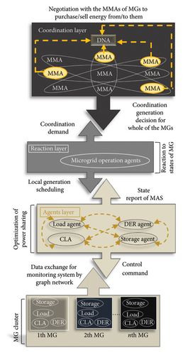
Resource agents: These include load agents, controllable load agents (CLAs), DER agents, and ESS agents at the primary layer for monitoring states of elements as setting operating points of LCs, state of charge of ESS, and dispatchable capacity of CLA.
- 2.
MG agents: It includes the MG operation agent (MOA) for managing the MG/MG cluster along with processing the optimal generation of dispatchable DERs and the MG market agent (MMA) for marketing the operation of the MG. MG cluster consists of several MGs converged in a coordinated pattern so that the MMA is responsible for negotiating with the MMAs of other MGs to purchase/sell power from/to them. The MG cluster must have a relationship with the distribution network agent (DNA) to comprehend the constraints of the energy market (see Figure 5).
- 1.
The reactive layer is often responsible for the voltage synchronization of buses through information exchange between agents. The process provides precision, recognition, and action models.
- 2.
The deliberative layer is the starting point for optimization issues such as self-sufficiency, realization of vision, and potential action models.
- •
The MAS has two types of functional nature: physical or virtual character. In terms of physical nature, an agent can be controlled in the role of a DER. However, virtual agents participate in the energy market, and therefore, these sell/reserve the measured surplus power [117].
- •
The presence of MAS in the electricity market, the complex relationship with DNO and MO in the third layer, and compliance with the local facilities on the customer side are the management challenges of MAS for supply and demand [10, 21, 86, 195].
- •
The programming-based complexity and the lack of professional knowledge of human operators cannot be ignored for the implementation protocols in MAS.
- •
The trade-off between the improvement of IRPS and V − f regulation is an important challenge for IMGs controlled by MAS.
- •
Dependency on the communication links that rely on the intervention of the global Internet to send/receive data to/from agent consensus by peer-to-peer structure leads to complicated problems such as the modeling complexity, mathematical computations, stochastic delay, costs, reliability in confronting cyberattacks, and the plug-and-play mechanism [84, 116, 117].
- •
The MAS suffers from stochastic delay because agents must use bidirectional communication graphs to exchange data with each other similar to the hierarchical structure.
3.4.2. Consensus Protocol
The MAS is the most developed distributed coordination control strategy according to the consensus algorithm [40, 161]. MASs are inherently adapted to the environment conditions because of the implementation by the node-graph (edge) protocol in each MG synchronization cycle.
- 1.
An edge-based adaptive consensus protocol that couples two nodes by a pair weight graph as a peer-to-peer network.
- 2.
A node-based adaptive protocol in which each node/agent is a database for the convergence of bidirectional LBC graphs that carry information about the environment (IMG), while time-varying weights manage the dynamic response of the MG.
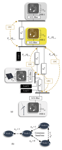
The consensus-based techniques can guarantee voltage deviation for the management of IMGs controlled by hierarchical and MAS structures, which are under threat from the IRPS [10, 21, 36, 40, 43, 70, 72, 97, 105, 113, 116–118, 124, 200]. Generally, the classification of consensus-based structures that can realize self-organizing control to improve or tackle SG problems is as follows: consensus with constraints [198, 201], event-triggered consensus [20–22, 24, 37, 58, 60, 71, 79, 109, 132, 134, 151, 180, 200, 202, 203], finite-time consensus [35, 46, 50, 52, 65, 183, 186, 204, 205], linear consensus protocol [206], heterogeneous consensus [43, 45, 127, 203, 207, 208], nonlinear consensus [23, 38, 45, 162], distributed averaging control [25, 161, 209], pinning-based distributed control [4, 8, 25, 86, 98, 106, 108, 150, 153, 161, 192, 199, 210, 211], and consensus programming-based control [23, 32, 48, 50, 55, 74, 106, 116, 127, 163, 198].
4. AVIDC-Based Volt-Var in MAS
The MASs controlled by self-adjusting droop or any other method can be implemented with/without a leader agent. At the same time, it observes SG by a possibly nonzero control for a time-varying input signal [196]. The first layer of MAS includes local elements such as RESs, VSCs, DERs, ESSs, and loads (controllable/uncontrollable) (see Figures 5 and 7). Meanwhile, the power sources can be controllable or not. For each DER, there is an agent with the same nature (controllable/leader or uncontrollable/follower). It is worth mentioning that if a resource is equipped with ESS, it will become controllable.
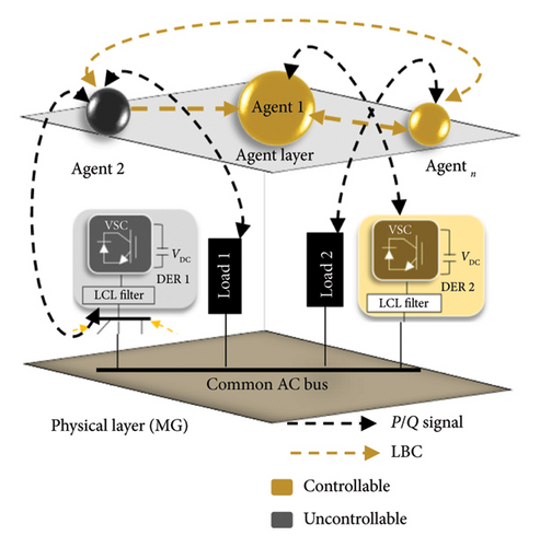
The interaction of the agents with each other is flexible in the sense that these show an adaptive behavior according to the influence of events in the environment (in terms of the failure in MG, load changes, system disturbances, battery charge, etc.). Assume that DER1 (by yellow agent) is controllable and DER2 to DERn (gray color) are uncontrollable units. If the environment is assumed to be the control of outputs for DER2 to DERn that installed at random distances, the reactive power flux changes. The environment changes are adapted according to the performance of agents that follow the controllability or uncontrollability of their sources in the second layer. Considering that, the agents must not be bounded by the parameters of their environment (as the influence of output impedance in (Q − V) control) [117]. Signaling the need to seek help from a controllable DER (leader agent), therefore, information of all the follower agents must be transferred to the leader agent, cooperatively. The leader agent corrects not only the reactive power sharing error but also the AC bus voltage drop, simultaneously. In this way, the LBC links between the agents estimate the impedance difference. Then, based on Equation (2), a virtual impedance value is calculated to compensate for the effects of output impedance mismatch. Thus, ZV is measured through graph theory in a consensus protocol to synchronize the voltages at the PCC. However, information exchange of the output voltage is limited by using constraints of adaptive droop control such as P/Q coupling and nonlinear loads [212].
In recent years, the consensus-based AVIDC schemes have been widely developed to compensate IRPS in off-grid mode [4, 8, 10, 16, 21, 27, 30, 36, 40, 43–47, 55, 70, 72, 97–100, 105, 107, 113, 116–118, 124, 200, 209, 213, 214]. In [215], a consensus-based AVIDC scheme is presented with a proportional-integral (PI) controller to compensate for the active power oscillations of paralleled VSCs. This adaptive controller uses a simple power control loop and ZV angle control to regulate the reference voltage drop and the variable phase angle caused by the mismatched output impedance of DERs without the requirement for knowledge of the line impedance. In [36], a consensus control technique by adaptive gain–slope adjustment is presented to improve the IRPS. In [100], a typical physical cyber-MG system with MAS-based automatic generation control is presented, which can compensate for the drawback of the droop control method for trade-off (Q − V), simultaneously. In [39], a two-layer theorem is discussed based on the MAS control to improve the IRPS, while it uses a systematic method for deriving SG control rules. Similarly, in [30], a two-layer subgraph structure is defined so that the task of the first subgraph layer is to guarantee the performance of all the agents that maintain the power balance between supply side and customer side. In the second control layer, the P/Q power sharing optimal is achieved even by reducing the number of edges. The optimal power flow is done by the leader agent in the second subgraph to obtain the optimized operating point, iteratively. Also, in [160], a multiobjective control strategy is introduced that includes a control scheme of paralleled VSCs to dictate V and f references at the first layer of IMG. In the second layer, an AVIDC is used to control VSCs of the first layer for tackling P/Q power sharing errors in a MAS. In [187], the hierarchical control structure is redefined by an adaptive droop-based MAS, while it defines a new zero level to facilitate the improvement of IRPS. The zero-level control and primary control can stabilize the V and f in the MG cluster and provide the reference voltage for the voltage source inverters (VSIs). In [105], a flexible droop control method is presented according to the consensus protocol control to correct the IRPS and unbalanced load sharing. This scheme obtains a reliable sinusoidal voltage at the PCC. Meanwhile, a secondary voltage regulator has also been used based on a PI controller to resolve voltage deviations, while it is not dependent on the impedance information of IMG. In [21], a consensus-based reactive power sharing technique is used by matrix analysis, while the unbalanced harmonic current sharing is covered, simultaneously. Nevertheless, this scheme is based on assuming a small phase angle between the output voltages of DERs. Therefore, it does not support voltage regulation. In [38], a consensus-based AVIDC is investigated in a multibus radial IMG. Approximately, the stable coupling gain range can be linearized around any operating point under the gain tuning guideline. In [96], a distributed negative sequence current sharing is introduced to compensate for unbalanced voltage and frequency deviation using a hierarchical dynamic consensus algorithm. Whereas the aim of the authors is not to directly improve reactive power sharing, it leads to a good IRPS compensation.
As mentioned earlier, the MAS-based distributed coordination control has often corrected the shortcomings of centralized, decentralized, and hierarchical structures according to artificial intelligence. To investigate the claim, the intelligent techniques that the MAS performance inherently depends on must be investigated. It determines how the essential challenges of an IMG such as the voltage regulation at the PCC and the IRPS, the plug-and-play mechanism, the complex modeling of LCs, and unavoidable delays are improved by MAS.
4.1. Pinning Control Algorithm
When the MG is disconnected from the bulk system, control commands are not received from the supervisory center; therefore, the new commands are received from the side of the agents. The pinning algorithm can pin a selected agent in the role of leader in each synchronization cycle of a MAS to a flagged environment. To select a set of pinned-leader and unpinned-follower agents, the distance and degree indexes are defined for the connection of the leaders relative to other MG devices [153, 199]. The process is defined in the last or third control layer to observe the output values [153, 192]. At the same time, the highest degree of authority of unpinned/follower agents is implemented for the last control layer to resolve V and f drop at the PCC. It means that a voltage observer receives the output voltage of all the DERs and then calculates the average voltage value at the primary level. Finally, the P/Q power sharing will be achieved based on pinned candidates at the secondary level [25, 153]. Thus, the dynamic MAS-based consensus averaging control must be pinned to at least one of the agents placed in the outermost control layer (second or third layers) [108, 150]. At the boundaries of the lower and upper layers, reference signals are extracted by the algebraic equations. These bounds can define a suboptimal algorithm with polynomial complexity. It flags nodes that are selected to pin the optimal network agents, efficiently [25, 199, 210]. It is worth mentioning that the operation of unpinned agents precedes the reaction of protective relays in the IMG [161, 199].
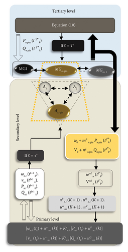
In several papers, the pinning algorithm can guarantee the performance of MASs to improve the IRPS [25, 86, 153, 196] and voltage regulation at the PCC [86, 153, 192, 210]. By some intelligent techniques such as the noroadaptive approximation technique, the fully distributed self-adjusting is asymptotically achieved. This situation holds even though the upper bounds of the nonzero inputs of the leaders and also the neural network approximation error are ambiguous for MAS [106]. In [199], the authors have proposed two adaptive algorithms for selecting pinned nodes(s), while it uses the degree and distance index of the selected leader(s) to other IMG segments according to [211]. Besides, a small part of the pinned agents is just capable of nonadaptive performance by simple feedback control. In [196], a droop control scheme is proposed for P/Q power sharing at the primary level of off-grid mode, while attaching a secondary level to the pinning algorithm implemented at the primary level completes the accuracy of trade-off (Q − V). In this case, the voltage source agents are pinned as virtual leaders. It means that the load agents are selected as a reactive and passive mechanism that is not pinned. In [86], a two-layer MG cluster is modeled, which generates current and voltage references based on P/Q power sharing errors between all the DERs. The pinned agents share the reference values with their neighbors at the secondary and primary levels for tuning voltage and frequency to nominal values. In [210], the ESS is considered as the leader agent by the algorithm-based pinning in the IMG.
Analyzing the above cases shows the most important advantages of the pinning-based MAS are to decrease controller/agent intervention and to make mathematical modeling more efficient. The most important form of the pinning control is relying on the NP-hard algorithm. Although NP-hard can solve the most complex computational problems with nonlinear binary programming, it causes the complexity of calculations that are classified in nondeterministic polynomial times.
4.2. Distributed Averaging Consensus Algorithm
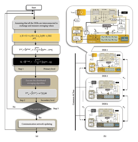
In an MG with k paralleled DERs, k = i, … j that is connected at the common current bus, LCs are equipped with a control circuit, which is not individual, necessarily (see Figure 9(b)). The added current control loop tracks the reference current provided by the common current bus. Moreover, a voltage observer located in each LC tracks the bus voltage, voltage drop at the PCC (in single-bus MGs), and output voltage of jth neighbors in each calculation cycle. In this way, the weights of a12, a1n, and a2n must be implemented during distributed averaging control to prove the plug-and-play mechanism in the cooperative structure. Another important feature is to provide a possibility for the LCs to overlap the complementary purpose of reactive power sharing and the bus voltage regulation as a trade-off, despite the nonlinearity and uncertainty of the modeling control system, disturbances, and different load characteristics (for both hierarchical and MAS structure) [21, 24, 25, 35, 40, 71, 72, 81, 97, 100, 161, 165, 209, 216].
- •
Step 1: This step includes the primary level to calculate V and Q references of each unit by integrators and . According to Section 5.2 and Figure 9(b), voltage and reactive power output values of jth DERs are sent to the ith unit through LBC links developed by consensus algorithm to calculate average voltage and reactive power sharing values as follows:
()() - •
where and are the voltage and reactive power output variations of DERs observed at the primary level. Also, , , , and are the proportional and integral terms of the DERs for V and Q averaging control, respectively.
- •
As an IMG is constantly exposed to sudden and rapid disturbances caused by the dynamic behavior of renewables and load changes, the existence of finite-time response control algorithms is essential for system stability during the converged average control. The use of finite-time consensus protocol suppresses data processing interference during reactive power sharing to restore voltage as an average value. According to this, the calculation of time-varying voltage vectors of the ith unit in a discrete-time interval is equivalent to its calculation in the entire continuous time interval as
() - •
Step 2: The controllable agents are responsible for setting averaging control gains. This step includes the secondary level to regulate the output voltage and improve the IRPS:
() - •
where is the averaging control input for a trade-off between Q and V, which is integrated based on and at the primary level.
- •
Step 3: This step observes the plug-and-play mechanism so that if it is Yes, the system goes to communication network update, and if it is No, it returns to Step 1 to monitor the j number of neighbors for receiving information from them through LBC links relative to the ith controllable agent. Then, it can calculate the average voltage and reactive power sharing by them of and QAvg, respectively.
- •
Step 4: The system is synchronized through the communication infrastructure of graphs.
The distributed averaging algorithm is often the basis of the control of autonomous intelligent MGs. In [25, 100], coordinated end-to-end information (such as average voltage and active power output of MG) is obtained for a trade-off between P/Q power sharing and V − f regulation. In [161], an AVIDC method based on the virtual synchronous generator is presented equipped with average consensus control to control (Q − V). However, this is a complex algorithm for voltage regulation and system stability. In [165], a secondary V − f control is proposed, which can play as a distributed averaging PI controller for trade-off between (Q − V). In [97], the averaging control-based trade-off (Q − V) scheme can limit the capacity of the bus’s voltage in an acceptable amplitude instead of average voltage regulation. In [216], a reactive power sharing technique is presented in terms of virtual shunt and series capacitor control, which recovers the system by using a fault-tolerant secondary control. The process is implied by a dynamic average consensus algorithm to compensate for the errors caused by deviations of the V and f in the IMG. In [65, 204], an averaging control scheme is presented for algorithmic time-limited global information sharing. This has acceptable transient behavior, meticulous control against uncertainties, and the proper features of restraining the disturbance. In this case, the agents indirectly use average data exchange and also a two-level fixed-time averaging control voltage and IRPS compensation strategy in [217]. It guarantees reference tracking before the desired fixed time is presented based on the sliding mode protocol and consensus-based MAS. In [40], a correction term ZV is derived from a consensus control approach implemented by a PI controller. This distributed averaging scheme is used to adjust the adaptive virtual inductance in the MAS structure. Another advantage is the suppression of circulating current and adjusting the output voltage of each DER. Nevertheless, the method just guarantees the configuration of paralleled microsources, and also, there is no idea to maintain the voltage close to the nominal value, despite voltage regulation. Despite the requirement of the distributed averaging algorithm for local control structures, the delay caused by the data between all DERs causes time delays.
4.3. Event-Triggered Control
In a conventional hierarchical control, a huge amount of unnecessary signals transfers from jth neighbor agents to the ith reference agent and vice versa, rapidly. It causes them to hurtle; therefore, the stochastic delay appears during the dynamic response. By event-triggered control, each agent has a degree of independence to sample events in alternating periods. Essential signals are chosen from among all unnecessary signals to deliver the agenti (yellow arrows in Figure 10). It significantly reduces unnecessary and time-consuming sampling of SG. Therefore, time delays are significantly reduced, and so the communication network capacity will be used more effectively. The sampling period is determined according to the density of the coordination task [20, 58, 60, 71, 79, 202, 203].
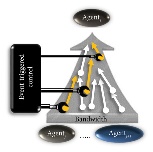
The start of sampling is from that moment when the measurement values of the MG deviate from their nominal values. It starts when thresholds are set for adjustable constant intervals, time-varying, or state-dependent tolerance paths [79]. It tracks the average of event time-varying reference signals in LCs affected by a group of consensus self-adaptive algorithms. This process is done according to the boundary layer approximation methods. Furthermore, it is updated by the measured error of the controllable quantities and the operating mode of the MGs.
The states of the jth neighbor agents are transferred to the ith reference agent by observing the instantaneous time information of the next event that is functionally necessary for the operation of the system. Moreover, the precision of the process is confirmed by experiments and systematic studies [109, 200]. Many of the available event-triggered mechanisms have threshold parameters that are always fixed. Nevertheless, adaptive approaches have been reported in the literature to solve problems of delay [79, 151]. The threshold parameter is adapted according to the triggering conditions with a dynamic event-triggered communication mechanism. It can be implemented by the consensus algorithm of the centralized power controller. Thus, the MAS-based attributed coordination control is established by power-balancing consensus algorithms with state-dependent thresholds [24, 202]. However, a load change event during the IRPS compensation can threaten the system stability. In [58], an approach for V − f regulation at the secondary control is reported by the event-triggered control in MAS. The outputs of the estimators approximate the actual values when the event is just triggered. The event-triggered algorithm prevents the processing of the estimated data. It can be done to reduce the time delay and bandwidth delay of the communication link. In [20, 180], synchronization signals are introduced by a classic event-triggered control to improve reactive power sharing. Nevertheless, the success of the proposed methods depends on the use of additional communication links to trigger the synchronization compensation steps. Moreover, the load changes are not foreseen during the IRPS compensation.
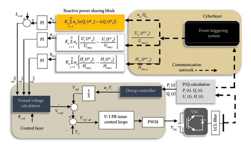
The virtual impedances are achieved to ensure both fundamental positive and negative sequences by signal and harmonic frequencies by signal for each individual microsource, where is input signal of unbalanced components from DERk=i⟶j to its nominal value Urate.i.j as well as suppressing harmonics of nonlinear components by to Hrate.i.j. Although it is done without requiring the knowledge of feeder information, it suffers from high interference of LCs, which can lead to another type of time delay.
Although the event-triggered control improves IMGs controlled by MAS, it has a complex operation, which does not guarantee the closed-loop system stability [20, 79, 180].
5. Scalability and Flexibility
The scalability of the MG controlled with AVIDC can be studied not only from the geographical point of view of the physical arrangement and installation of ground equipment and units but also from one of the four centralized/hierarchical and decentralized/distributed bases on multiagent structures due to the high dependency on the low-/high-bandwidth communication infrastructure. In centralized structures, due to high reliance on high-bandwidth telecommunications, the scalability of MG controlled with AVIDC is lower than other structures from both points of view. However, control versatility, reliability, and plug-and-play mechanisms are not guaranteed. In a hierarchical structure that has a glance at centralized control (due to the presence of MGCC and three-level control) and another glance at a decentralized structure, the scalability is bigger than centralized control. This issue in the multiagent control structure is bigger than centralized/hierarchical with high complexity and safety and with less bandwidth occupancy due to the use of peer-to-peer connection implemented by consensus protocol, whereas, in the decentralized structure, due to the absence of communications and independence from the MGCC, the highest level of scalability and geographical extent is observed.
From the point of view of MG architecture, the main aim of adaptive droop control is to achieve coordination and integration with various types of MG configurations such as radial and meshed models [218], even if MGs are implemented in different structures. According to many articles, this controller can match all types of AC MGs, hybrid AC/DC MGs, and DC MGs [69, 115, 219–232].
Also, this aim is completed by achieving a plug-and-play mechanism for all DERs, so that each unit can connect/disconnect from each desired point of the MG, without the need to change other points of the MG or its control structure. Conversely, these aims depend on the type of MG control approach. In centralized and hierarchical structures, due to the existence of communications, the controller easily adapts to the MG structure. However, in the distributed control structure based on a multiagent and decentralized manner, it is more difficult to achieve adaptive performance. Preferably, researchers in the field of adaptive droop control often provide decentralized and distributed control solutions. It is worth mentioning that as this article has a reviewing structure, what we mean by impedance-based adaptive droop control refers to a wide range of control methods. However, all of these cannot have the same success in achieving the AVIDC’s aims.
Finally, in Table 1, information on several real-world MGs controlled by AVIDC is collected, which can switch between the connected and islanded modes compared to the main grid.
| Country | Name | Capacity | Control structure |
|---|---|---|---|
France  |
ARMINES MG [233] | With 3.1-kW solar panel, 3.2-kW diesel generator, 1.2-kW fuel cell, and 18.7-kWh EES | An MG project based on a centralized structure |
Greece  |
Kythnos MG (Aegean Sea) | Isolated 10-kW solar panel, 5-kW diesel generator, and 53-kWh battery | An MG project based on centralized/distributed control |
| National Technical University of Athens MG [233] | 1.2-kW solar panel, 1-kW wind turbine, and 4.5-kW EES | An MG project based on hierarchical realized on the Jade 3.0 platform implemented in multiagent architecture | |
Korea  |
Hyundai Samho Heavy Industries [234] | An islanded MG with 2000 kVA apparent power | An islanded MG as a shaft generator system in huge ships equipped with a squirrel-cage induction generator and an adaptive observer for estimating the stator resistance in the form of virtual impedance |
Australia  |
Flinders Island [235] | 0.5 MW of PV and 0.5 MW of ESS merged with 2.0 MVA of other types of generators | An AC/DC hybrid standalone MG placed in the Bass Strait between the northern tip of Tasmania and Melbourne in Australia |
6. Regulatory and Standardization of AVIDC-Based Technologies
Standards are a road map to facilitate control processes such as power quality control, voltage and frequency regulation and system stability, exploitation of sources and fair P/Q sharing, protection, and security of the network, supporting the consumer’s rights, and supplying hardware devices and tools. These standards are based on a recording of experimental results with all the constraints of generation and networking and provide directional cost effectiveness (profit on the side of generation and consumption). Generally, the standards are divided into two categories: international and national. In scientific research, authors often prefer to act according to the standards of their institutions and research centers, and just limited research has compared the results with international or national standards. Both standards should be compared and concluded from the technical, geographical, historical, and experimental points of view of the studied technology.
- •
Networking and convergence of sources: DER standards are approved based on the feasibility of connection and disconnection (islanded mode) to the main network, internal connections between sources and their convergence, design, modeling, mathematics, and the possibility of monitoring the output values of all operating units. Based on this, AVIDC can operate in all conditions of the MG as a comprehensive and fast technique, with the ability to converge and participate in all units feeding the loads according to their contribution to the nominal power value. This conforms to standards of IEEE Standards series (2003), IEEE 1547 (2018) A and B; I and II categories, IEEE 1547-(2-6), and IEEE 2030 (1-11), IEC 62898 1, 2, and 3 series, CENELEC standard, and German standards.
- •
Prepare the ground for intelligence: The AVIDC method requires proper design in modern MGs to present the most accurate and fastest performance. Standards such as IEEE Standards series (2003), IEC 62898 1, 2, and 3 series, IEEE 1547-6, and IEEE 2030, cover requirements for source allocation as the main protocol of future SGs.
- •
Integration of ESSs into MGs: IEEE 2030 and IEC 62898 standards cover the energy management and storage of MGs; however, the IIEEE-1547-4 standard does not have a specific plan for this purpose.
- •
Maintaining power quality: This aim includes the following [233]:
- a.
Suppression of harmonic components and unbalanced load according to standards Harmonic Standards 519-1992, EN 50160 standard, IEC 61000, IEC 61727, IEC 61000-4-7, and IEC 61000-3-13.
- b.
Power factor control according to European standards, CENELEC standard, Germany BDEW, Germany VDE-AR-N4105, and IEC 62898 1, 2, and 3 series.
- c.
Reliability and stability almost correspond to most of the standards in the table.
- d.
Voltage regulation according to IEEE Standards series (2003), IEEE Harmonic Standards 519-1992, IEEE 1547 (2018) A and B, IEC 62898 1, 2, and 3 series, and IEC 61000-3-13:2008, with European standards, CENELEC standard, Germany BDEW, and Germany VDE-AR-N4105.
- e.
Reactive power control according to CENELEC standard, IEC 62898 1, 2, and 3 series, and IEEE 1547 (2018) A and B.
- a.
- •
Coordination with the economic tariffs of the electricity market according to the CENELEC standard, IEC62898 1, 2, and 3 series, and IEEE 2030 series.
| Origin | Standard | Properties | ||
|---|---|---|---|---|
American  |
IEEE Standards series (2003) |
|
||
| IEEE 1159 standard [236] | • Power quality control | |||
| Institute of Electrical and Electronics Engineers (IEEE) 519 [237, 238] |
|
|||
| IEEE Harmonic Standards 519-1992 [239] | Bus voltage | Individual voltage orders (%) | THD (%) | |
| V < 70 KV | 3.0 | 5.0 | ||
| 70 ≤ V < 161 KV | 1.50 | 2.50 | ||
| V ≥ 161 KV | 1.0 | 15.0 | ||
| IEEE-1547-a (2014) |
|
|||
| IEEE 1547 (2018) A and B; I and II categories |
|
|||
| IEEE 1547-2 | • Variation forms of DER technologies and interconnection issues | |||
| IEEE 1547-3 | • Fluctuation–parameters–methodology–monitoring–information exchange for stakeholder for MG | |||
| IEEE 1547-4 |
|
|||
| IEEE 1547-6 | Spot and using auxiliary distribution grids from the point of view of design, components, and operation | |||
| IEEE 2030 1-11 series |
|
|||
European  |
International electrotechnical commission (EN) 50160 standard [240] |
|
||
| IEC 61000 [237] | • Mitigating harmonics and interharmonics in low-frequency cases | |||
| IEC 61727 [241] |
|
|||
| IEC 61000-4-7 [242] |
|
|||
| IEC 61000-3-13:2008 [243] | • Definition of a factor for analyzing the total voltage unbalance to both supply side and demand side | |||
| IEC 62898 1, 2, and 3 series [233] |
|
|||
| CENELEC standard [233] |
|
|||
Germany BDEW [233]  |
|
|||
Germany VDE-AR-N4105 [233]  |
|
|||
- Note: Interharmonic mean noninteger multiples of the fundamental frequency.
7. Economic and Environmental Impact of AVIDC-Based Technologies
Investigating the impact of AVIDCs on the economy of power systems can be a double-edged sword. Due to the use of modern communication technologies despite occupying bandwidth, relying on complex control devices, and using advanced power electronic components, RESs, etc., the cost of capital may increase initially; however, this is a long-term investment on both sides of demand and supply. This is realized by reducing and eliminating network elements such as transmission networks, traditional power plants, and power losses. These economic benefits are further enhanced by power management through ESS. Optimization algorithms are approaches to achieve the optimal set point of a variable for the objective function so that it results in the least cost and time. These algorithms provide a possibility to achieve the optimal operating points of the main output variables of MGs. Regardless of which platform runs the optimization algorithm such as hierarchical structure [34, 68, 74, 85, 123, 152, 154, 168, 172, 175, 176, 179, 183, 244, 245] or MAS control [23, 30, 32, 55, 116, 127, 163, 198], it requires a secondary level equipped with a consensus algorithm for running optimization.
The characteristics of this concept are classified in Table 3.
| Control method | Advantage | Disadvantage |
|---|---|---|
| • Genetic algorithm [34, 88, 244] | • Robustness [23, 34, 154, 176] | • Huge computing burden [60, 198] |
| • Model predictive control [50, 60, 68, 74, 163, 176, 245] | • Guaranteeing the plug-and-play mechanism [34, 50, 154, 178] | • Dependency on complex control algorithms |
| • Fuzzy logic control [94, 168, 173] | • Resilience [154, 176] | • Lacking influence of practical factors on prediction [50, 60, 68, 74, 163, 176, 245] |
| • Neural networks [74, 94] | • Fast dynamic response [94, 244] | • Low expandability |
| • Particle swarm optimization [32, 94, 175] | • Reducing the cost by redesigning the reasonable cost function [50, 154, 179] | • Dependency on multilevel communication links or MGCC |
| • Mixed-integer linear programming [172] | • The V − f regulation [50, 94, 168, 175, 176, 183, 244] | • Influence of delay/data drop in the calculation algorithm [113] |
| • Mixed-integer nonlinear programming [179] | • System stability [94, 175, 176, 245] | • Threatening of system stability by stochastic delays |
| • Accurate power sharing between all the DERs [55, 172, 183] | • The requirement of the data analysis and cumbersome computational load | |
| • Resistant to constant time-varying communication delays [74, 172, 183] | • The requirement of the prior knowledge of parameters of MG for estimation-based techniques | |
| • Ensuring the safety of equipment | ||
| • Minimizing data drop [113] |
Certainly, the purpose of RESs is to help reduce environmental problems, but there are equivocal issues. The gradual development of low-carbon MGs controlled by AVIDC has significantly prevented the development of biological hazards. However, AVIDCs developed with wind and solar modules, etc., may create environmental problems such as finding a suitable location for installation far from agricultural lands, pastures, water sources, and animal ecosystems. If these points are not feasible, they may disrupt the pollination of plants and cause a lot of noise. Finally, chemical pollution caused by nonrenewable electronic waste, the threat of communication noise to human health, and the interference in electronic devices are other challenges of AVIDC. Definitely, in the strategic documents of SGs, appropriate standards have been established. It is worth mentioning that by improving the control of reactive power sharing, using AVIDC, the power loss is minimized. Also, it can significantly reduce the harmonics, noises, and disturbances of power systems; as a result, it helps to reduce the health risks of humans and fauna.
8. Performance Evaluation
What differentiates a controller from its rivals is its ability to overcome disturbances to maximize achieving various system objectives. In Table 4, AVIDC’s premium features in four communication infrastructures are collected based on the latest published articles. As the power system becomes more intelligent and tends toward MAS control, it has a more successful performance.
| Features | Centralized control | Decentralized control | Hierarchical control | MAS-based control |
|---|---|---|---|---|
| Precise compensation of the IRPS | According to [61, 78, 128] | According to [7, 10, 11, 13, 14, 16, 19, 27–29, 33, 53, 54, 62, 70, 86, 90, 94, 95, 102–104, 113–116, 118–125, 128, 137, 138, 165] | According to [6, 9, 16–20, 23, 24, 29, 46, 55, 67, 72, 85, 88–90], [93, 94, 101, 104, 123, 125, 146, 165–179, 246, 247] | According to [2–4, 10, 21, 23, 30, 31, 36–39, 41, 43–47, 60, 65, 74, 96, 97, 105, 107, 113, 123, 139, 165, 196, 209, 212–217, 248] |
| V − f regulation | According to [130, 132] | According to [7, 33, 90, 103, 142, 144, 145, 249–253] | According to [6, 18, 58, 92, 93, 98, 116, 125, 146, 149, 165, 168–170, 173–175, 181, 190, 247, 254, 255] | According to [21, 23–25, 30, 32, 35, 36, 38, 40, 43–47, 55, 58, 65, 96, 97, 100, 105], [107, 116, 123, 153, 160–162, 165, 176, 183, 187, 196, 204, 212–217, 248] |
| Accuracy of current sharing | According to [125, 128] | According to [251, 256–258] | According to [228, 259] | According to [21, 40, 64, 81, 96] |
| The degree of control complexity | Simple for MG and complex for monitoring purposes by EMS; according to [118, 126, 127, 132] | Relatively simple | Complex; according to [9, 55, 88, 94, 101, 146, 167–177, 179, 183, 189] | High complex |
| System stability | According to [46, 130, 132] | According to [7, 18, 19, 27, 28, 31, 33, 62, 70, 81, 86, 94, 103, 104, 119, 125, 140], [142, 144, 145, 157, 225, 228, 246, 247, 249–253, 256, 260–269] | According to [18, 72, 98, 117, 125, 143, 146, 149, 165, 169, 170, 173–175, 181, 183, 189, 247, 254, 255] | According to [21, 25, 29, 30, 32, 36, 43, 58, 65, 67, 86, 200, 204, 215, 270] |
| Ability to coordinate all the resources | Unacceptable; according to [148] | Unacceptable | Acceptable | High acceptable |
| Scalability and resilience | Unacceptable | Relatively acceptable; according to [18, 27, 104, 141, 256, 260, 263, 271–273] | High acceptable; according to [6, 89, 116, 143, 189] | High acceptable; according to [23, 58, 84, 105, 212, 270] |
| Plug-and-play mechanism | No | Yes; according to [27, 70, 133, 138, 146, 225, 257, 270, 274, 275] | Yes; according to [117, 178, 255] | Yes; according to [10, 36, 37, 50, 73, 97, 117, 210] |
| Reliability | No | Yes; according to [18, 27, 70, 133, 138, 146, 225, 270, 273, 274] | Yes; according to [168, 178, 255] | Yes; according to [25, 43, 58, 105, 185, 200] |
| Redundancy | High | Low | High | High; according to [10, 125, 276] |
| Extensibility (in terms of geographic scope) | No | Yes | Yes | Yes; according to [10, 125, 276] |
| Robustness | According to [61, 78, 117–119, 122, 123, 126–129] | According to [115, 118, 133, 225–227, 257, 269, 270, 272, 275, 277–281] | According to [117, 125, 143, 174] | According to [6, 10, 23, 37, 41, 50, 67, 72, 97, 108, 117, 210, 212, 248, 282] |
| Suffering from stochastic delays | No; to rely on real-time process; according to [14, 41, 61, 103] | No; to rely on the primary level; according to [268] | Yes; to use LBC links; according to [118, 125, 168] | Yes. However, it can be overcome; according to [21–23, 25, 30, 36, 39, 41, 56, 58–60, 63–65, 67, 68, 70, 71, 73–75, 107, 109, 199, 204, 213, 214] |
| Ability to mitigate harmonics | Guaranteed; to obey received commands from the central controller | Nonguaranteed; according to [16, 19, 29, 135, 136, 142, 225–227, 273, 283] | Guaranteed; to obey received commands from MGCC; according to [11, 17, 25, 28–32, 51, 93, 96, 178, 228, 254, 259] | Guaranteed; to obey received commands from agents; according to [21, 22, 105] |
| Improvement of power loss | Acceptable; to obey received commands from the central controller | According to [29, 178, 251, 273] | No valid information | According to [113, 248] |
| Cost-effectiveness | No | Yes; according to [115, 118, 133, 225–227, 257, 269, 270, 275, 277–281] | No; according to [9, 55, 88, 94, 101, 146, 166–179] | Relatively yes; according to [23, 32, 50, 55, 198] |
| Dependency on the knowledge of MG parameters | Yes | No; according to [19, 90, 247, 250, 251, 264, 265, 284] | No; according to [117, 125, 126, 170] | No; according to [22, 105, 215] |
8.1. Comparison of AVIDC With Other Adaptive Control Approaches
- 1.
Droop-free method [81, 104, 141, 260]
- a.
Master–slave: In this technique, the output current of DERs must be permanently adapted with a reference DER in a slack bus. Therefore, these are not safe during current overshoots in the different load conditions. Also, this method requires a central controller and bandwidth occupancy. Furthermore, it does not have a guarantee for the plug-and-play mechanism (due to the existence of the slack bus), so reliability and stability are at risk for different loading conditions.
- b.
Sliding mode: This technique achieves the purpose of system stability without emphasis on power sharing. However, if it is done while covering different loading conditions, it suffers from the chattering phenomenon, and so its accuracy is precarious. Furthermore, it requires the observer and bandwidth occupancy.
- a.
- 2.
Droop-based method
The nonimpedance-based droop methods such as the angle droop method do not guarantee reactive power sharing in different loading conditions, and active power sharing is often discussed [261]. Thus, compared to other rivals, AVIDC can recover voltage deviations under different load conditions while supporting reactive power sharing simultaneously. Moreover, it guarantees the plug-and-play mechanism because it does not include a slack bus and DER reference so that all sources are parallel. In Table 5, the features of AVIDC are compared with other adaptive methods.
| Type of control method | Advantage | Disadvantage | |
|---|---|---|---|
| Droop-free methods | Master–slave [10, 81, 104, 125, 141, 288] |
|
|
| Sliding mode [10, 104, 260, 269] |
|
|
|
| Droop (impedance-free) methods | The (P − ω)/(Q − V) dot droop [285, 286, 289] | ||
| The angle droop control [261] |
|
|
|
| The virtual flux droop technique [287, 291] | • Nonguaranteed voltage regulation [287, 291] | ||
| Comparison | Impedance-based adaptive droop control (AVIDC) |
|
|
- Note: In some papers, the multiagent structure is categorized as a droop-free method, which can merge with the droop method.
8.2. The Major Technical Challenges of AVIDC
- •
This controller relies on nested control loops, which cause the complexity of the system and, as a result, increase the time delay of the dynamic response.
- •
To control the trade-off between reactive power sharing and voltage regulation, it is not yet able to provide a fully guaranteed approach.
- •
When the IMG is faced with harmonic and unbalanced critical load characteristics, the error correction compared to the reference values is carried out by PI controllers in the dq framework, which has no successful performance in suppressing nonsinusoidal outputs, improving voltage THD, and a desired dynamic response. It just measures the phase error [92, 232, 292–297]. Therefore, the authors have tended toward relatively favorable PR controllers in the αβ framework. Although PRs have a favorable dynamic response and can be designed in single-phase and three-phase fields, they are affected by frequency fluctuations and are not acceptable for operational MGs [92, 173, 292–301]. In addition, both PI and PR controllers need detuning.
- •
Some AVIDCs depend on knowledge of MG parameters and information [13, 301–304].
- •
AVIDCs require active filters and preferably passive filters [231, 305] for compensation, which increases the size and cost of the system from the point of view of high dependency on hardware components, and the system constantly requires the detuning of coefficients; otherwise, the stability of the system is disturbed [19, 22, 93, 231, 305–314]. There is also the possibility of a lack of desired frequency response and phase shift in some frequencies. In practical examples, it is possible that the system’s improper switching will be damaged.
- •
All AVIDCs are not guaranteed to work in two modes, connected and disconnected from the network, and synchronize between these two modes.
- •
With the addition of renewable sources including wind turbines and solar panels, there is no guarantee for the desired implementation of AVIDC in practice.
9. Future Research Directions
- •
Improving voltage and frequency control and stability of IMGs.
- •
Investigating the impact of AVIDCs on the suppression of harmonic and unbalanced components of output voltage and current.
- •
Investigating the performance role of active and passive filters developed with AVIDC control.
- •
Control analysis of real RESs such as solar and wind modules under AVIDC performance.
- •
Investigating the performance of AVIDC in low-voltage MGs with a low X/R ratio.
Based on the future innovations proposed in the last option, the performance of AVIDC can be simulated in a resistive MG used in a decentralized structure, using a novel adaptive control strategy to improve power sharing. Then, the results are compared with the simulation results of an inductive similar MG.
9.1. Application of AVIDC in Resistive MGs
In this situation, AVIDC is required to calculate a virtual resistance, instead of virtual inductance, according to the system disturbances to compensate for the mismatched voltage drops caused by the mismatch of the output impedances. In this way, the resistance component of the virtual impedance overcomes the inductance component. This section implements a case study to provide more information about resistive MGs.
9.2. A Case Study
In this section, a case study is investigated to show how AVIDC can work in resistive MGs. It is an IMG with nominal frequency f = 50 Hz and line-to-line voltage VL−L = 390 V, simulated using Altair PSIM software. The system is equipped with two parallel DERs with apparent power equal to 10 kVA. Each microsource has a separate control unit, similar to other units. The resources are connected through LBC links according to Figure 12.

9.2.1. Proposed Control System
The control scheme is implemented by a process to adjust the virtual impedance value. This process consists of two operating modes, including the conventional droop/boost mode and adaptive virtual impedance tuning mode. Previously, [321] proposed a similar control approach to improve reactive power sharing in inductive IMGs. The effect of adaptive virtual impedance control in a low-voltage MG with a low X/R ratio will be studied in this paper.
Normally, all sources work in constant voltage mode. The adjustment process started with a coordinating signal, which requires a LBC link. Then, all sources switch between two operating modes sequentially using internal timers. In the conventional droop/boost mode, each source implements (P − V) and (Q − ω) characteristics to find a better working point from the viewpoint of active power sharing. The equations of the conventional droop process can be recalled from Equations (31a) and (31b). After a short time, the controller enters the adaptive virtual impedance tuning mode. In this mode, the virtual resistance value is adjusted based on the results of the previous mode.
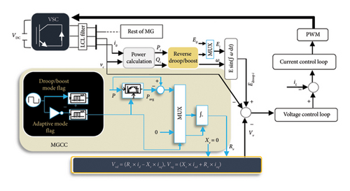

The parameters of MG and controller are detailed in Table 6.
| Microgrid parameters | Value | Controller parameters | Value |
|---|---|---|---|
| Lf1 = Lf2 | 360.76 × 10⁻⁶ | PI controller in V–I inner loops | Kpv = 1 |
| S1 = S2 | 10 kVA | Kiv = 100 | |
| Cf1 = Cf2 | 103.6 × 10⁻⁶ | Kpc = 1 | |
| Load 1 | 0.0693 + j0.0002 Ω | Kic = 10,000 | |
| Load 2 | 0.0343 + j0.0001 Ω | ωc = 62 Hz | |
| Resistive MG | ∆f | 0.0.1 Hz | |
| ZLine1 | 0.1226 + j0.0245 Ω | ∆V | 0.02 pu |
| ZLine2 | 0.0300 + j0.0060 Ω | Kavi for conventional droop | 10 × 10−6 |
| Inductive MG | |||
| ZLine1 | 0.0245 + j0.1226 Ω | Kavi for reverse droop | 1.8 × 10⁻⁶ |
| ZLine2 | 0.0060 + j0.0300 Ω | ||
9.2.2. Simulation Results
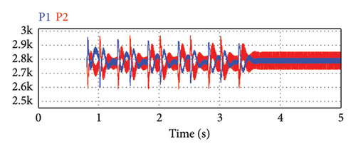
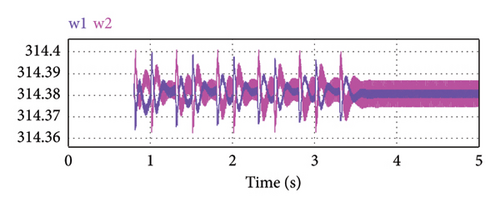
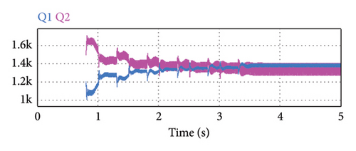
The simulation results can be analyzed according to Figure 15. In Figure 15(a), the active power flow tends toward equal values of load sharing between the two parallel DERs using the adaptive virtual resistance control mode. As active power sharing is a function of voltage regulation, the microsources output voltage variations during the virtual resistance adaptation process can be observed in Figure 15(b). Now, the controller can adjust the voltage in an acceptable range near the nominal value. In Figures 15(c) and 15(d), reactive power and the angular frequency of microsources are illustrated, respectively. As can be seen, the reactive power sharing remained ideal and the frequency is in an acceptable range near the nominal value. In the adaptive tuning mode, the MG frequency stabilizes toward the nominal value. In addition, compared to Figure 15, Figure 14 can be studied using AVIDC in inductive IMGs.
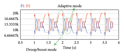
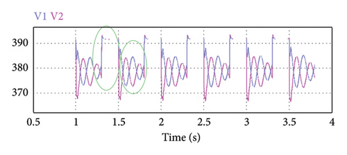
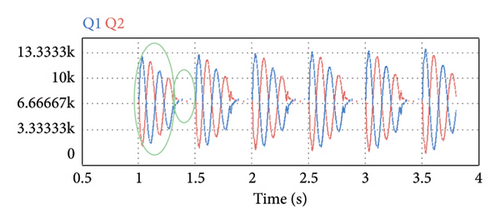
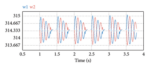
According to Figure 14(a), active power sharing is often maintained in the droop-controlled inductive MG. Subsequently, the MG frequency also tends to the nominal values in Figure 14(b) with the allowed tolerance. Thus, the two control modes finally converge to control the reactive power sharing as shown in Figure 14(c). Also, the IMG voltage is set at the nominal value (see Figure 14(d)). It is worth mentioning that in inductive MGs, Equation (32) must be rewritten in terms of Q instead of P.
Based on the obtained results, it can be concluded that by correctly adjusting the gain of the adaptive controller in terms of P and Q, without the need to change the droop slope, an acceptable response can be obtained from AVIDC in both resistive and inductive MGs.
10. Conclusion
The purpose of this paper is to illustrate improving or eliminating techniques of the reactive power sharing error according to the AVIDC in centralized, decentralized, hierarchical, and MAS-based distributed coordination control structures. The IMG control methods are often based on a hierarchical structure; otherwise, centralized control is implemented. Nevertheless, the hierarchical structure emphasizes the use of the MGCC and the time-varying LBC links, and so it suffers from unwanted delay. Although centralized and hierarchical structures affect power quality concepts such as reliability, cost effectiveness, and flexibility of LCs, the power supply side conservatively uses these structures because of the lack of standards. Finally, the MAS-based distributed control provides the smartest infrastructure that draws inspiration from the advantages of three centralized, decentralized, and hierarchical structures to improve their disadvantages. The consensus-based MAS is a self-control pattern with a configuration similar to hierarchical control, except that MGCC attendance is canceled. This structure is equipped with a consensus protocol so that each LBC link is assumed as a graph, and each agent as a node to transfer information of the reactive power and voltage of the output of the DERs between all the agents. In this paper, the algorithms that determine the merits of MAS-based distributed control have been analyzed such as event-triggered control, pinning algorithm, distributed averaging control, and finite-time control. These can reduce delays caused by data exchange traffic through the communication network, the complexity of multiloop control algorithms, and the asymmetric trade-off between Q and V, with respect to the consequence of the mentioned algorithm in the last sentence. Moreover, the existence of average control can guarantee the plug-and-play mechanism in the IMGs. Also, the intervention of LCs along with complex modeling can be reduced by the pinning algorithm. Nevertheless, several challenges remain as unsolved drawbacks for MAS such as nested control loops, relying on knowledge of MG parameter information, and the threat of cyberattacks. Therefore, cybersecurity protocols are required to manage vulnerable smart systems.
Nomenclature
-
- ABE:
-
- Attribute-based encryption
-
- AVIDC:
-
- Adaptive virtual impedance droop control
-
- BESS:
-
- Battery energy storage systems
-
- DER:
-
- Distributed energy resource
-
- DNA:
-
- Distributed network agent
-
- DNO:
-
- Distribution network operator
-
- DMS:
-
- Distribution management system
-
- EMS:
-
- Energy management system
-
- HBC:
-
- High-bandwidth communication
-
- IMG:
-
- Islanded microgrid
-
- IRPS:
-
- Inaccuracy of reactive power sharing
-
- LBC:
-
- Low-bandwidth communication
-
- LC:
-
- Local controller
-
- MAS:
-
- Multiagent system
-
- MMA:
-
- Microgrid market agent
-
- MG:
-
- Microgrids
-
- MGCC:
-
- Microgrid central controller
-
- MPC:
-
- Model predictive control
-
- MO:
-
- Market operator
-
- MOA:
-
- Microgrid operation agent
-
- PCC:
-
- Point of common coupling
-
- PCS:
-
- Physical cybersystems
-
- PI:
-
- Proportional integral
-
- PLL:
-
- Phase-locked loop
-
- PMU:
-
- Phasor measurement unit
-
- PSO:
-
- Particle swarm optimization
-
- RES:
-
- Renewable energy sources
-
- SCADA:
-
- Supervisory Control and Data Acquisition
-
- SG:
-
- Smart grid
-
- VSC:
-
- Voltage source converter
-
- VSI:
-
- Voltage source inverter
-
- WAMS:
-
- Wide-area measurement systems
Conflicts of Interest
The authors declare no conflicts of interest.
Funding
No funding was received for this research.
Open Research
Data Availability Statement
Data sharing is not applicable to this article as no datasets were generated or analyzed during the current study.


