Magnet Shape Modeling in Slotless Axial Flux Permanent Magnet Machines Under No-Load Conditions
Abstract
This paper presents a new 3D analytical model based on the Fourier–Bessel series for electromagnetic modeling of the performance of slotless axial flux permanent magnet (AFPM) machines under no-load conditions. The machine geometry is divided into different domains including the permanent magnet (PM) domain, the air-gap domain, and so on. The Laplace equation in terms of scalar magnetic potential is solved in each domain, and their solutions are expressed based on the Fourier–Bessel series to accurately consider the radial variation of the air-gap magnetic field. A 2D geometry function based on the Fourier–Bessel series is introduced to accurately consider the different PM shaping in the magnet domain. The boundary condition is then used to determine the unknown constants in the general solutions. This 3D analytical model is prepared to calculate the no-load flux linkage of stator phases while considering different PM shapes and skewing effects. Two indexes including the amplitude of the fundamental component and the total harmonic distortion (THD) of no-load phase flux linkage are considered to investigate the effect of skewed PMs and other PM shapes. The capability of the proposed 3D analytical model is also presented to calculate the air-gap magnetic field due to the stator phases for determining the inductance matrix. Finally, the accuracy of the proposed 3D analytical model is verified by comparing it with the corresponding results obtained through the finite element method (FEM) and the experiment setup.
1. Introduction
Slotless axial flux permanent magnet (AFPM) machines have found various applications in industries due to the lack of cogging torque and low vibration [1, 2]. For this reason, the accurate 3D modeling of slotless AFPM machines is necessary to calculate the air-gap magnetic field. The finite element method (FEM) is the most famous technique for the performance analysis of the AFPM machines [3, 4]. The field reconstruction method which acts based on the FEM was used in [5] for the analysis of one AFPM machine. The FEM can accurately consider all nonideal effects such as the magnetic saturation and the slotting effect. However, the FEM is a time-consuming technique for 3D modeling of the AFPM machines. For this reason, it should be better only used in the final stage for verifying the analytical results [6]. The analytical techniques which have been so far used for modeling and analysis of the AFPM machines are, respectively, the quasi-3D models, the magnetic equivalent circuit (MEC) model, and the subdomain (S-D) model.
The most commonly used analytical model for the analysis of the AFPM machines is the quasi-3D analytical model. In this model, the geometry of the AFPM machine is divided into several annular slices in the radial direction to consider the curvature effect due to the radial variation of geometry. The 2D analytical models and the law of superposition are then used to analyze the 3D model. The quasi-3D model based on the FEM was used in [7]. The quasi-3D model based on the harmonic magnetic modeling in the Cartesian coordinate was proposed in [8]. The quasi-3D model based on one S-D model was presented in the mean radius of axial flux eddy current brakes [9, 10] and in different radii of the AFPM machines [11]. The quasi-3D model based on the MEC model was used in [12, 13] for the electromagnetic analysis of the AFPM machines. The quasi-3D model based on the combination of the solution of Maxwell’s equations in the air-gap region and the MEC model in the iron parts was presented in [14]. Generally, it can be said that the accuracy of quasi-3D models increases as the number of 2D models in different radii increases. Also, the edge effect which is caused by the unequal radial length of the rotor and the stator cannot be considered by using the quasi-3D models. For this reason, the correction factor obtained through the FEM was used to consider the edge effect in the air-gap magnetic field results of the quasi-3D model [15, 16]. The 3D MEC model can be used to model and analyze the AFPM machines [17]. However, the MEC model is not user-friendly and it is not accurate for calculating the air-gap magnetic field components. The 3D S-D model has been also used for electromagnetic analysis of the AFPM machines without considering the edge effect [18].
This paper presents a 3D analytical model for the electromagnetic analysis of the slotless AFPM machines which can consider the curvature effect of the PM geometry and the edge effect due to the different radial lengths of the stator and rotor cores. This paper is organized as follows.
The main parameters of analyzed AFPM machines are introduced in Section 2. The principle of the proposed 3D analytical model is presented in Section 3. The flux linkage calculation by using the proposed analytical model is presented in Section 4. The conclusions of the work are given in Section 5.
2. Parameters of the Studied AFPM Machine
The main parameters of the analyzed single-sided 3-phase slotless AFPM machine with the axial magnetized trapezoid and rectangle PMs are introduced in Table 1. The views of the rotor and stator disks of the studied AFPM machine with sector-shaped PM and radial coils have been illustrated in Figure 1.
| Parameter | Value (unit) |
|---|---|
| Outer radius of stator back-iron (rso) | 150 (mm) |
| Inner radius of stator back-iron (rsi) | 100 (mm) |
| Height of stator back-iron | 10 (mm) |
| Number of coils | 24 |
| Height of coil | 4 (mm) |
| Width of coil | 7 (mm) |
| Number of turns per coil | 51 |
| Air-gap length | 2 (mm) |
| Outer radius of PM (rmo) | 155 (mm) |
| Inner radius of PM (rmi) | 95 (mm) |
| Number of PMs | 16 |
| Height of PM | 2.5 (mm) |
| Ratio of pole arc to pole pitch (trapezoidal PM) | 0.8 |
| Width of rectangle PM | 30 (mm) |
| Length of rectangle PM | 60 (mm) |
| Outer radius of PM back-iron (rro) | 160 (mm) |
| Inner radius of PM back-iron (rri) | 90 (mm) |
| Height of PM back-iron | 10 (mm) |
| Remanence of PM (BR) | 1.2 (T) |
| Relative permeability of PM | 1.1 |

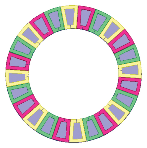
As shown, the stator phases and rotor PMs are illustrated with different colors for more clarity.
3. Proposed 3D Analytical Model
In the proposed 3D model, the machine geometry is divided into several domains. The 2D cross sections of the slotless AFPM geometry in the r − z plane and the φ − z plane are shown in Figure 2. The proposed 3D model can also consider the edge leakage fluxes and the leakage flux between adjacent PMs, which are shown in Figure 2.
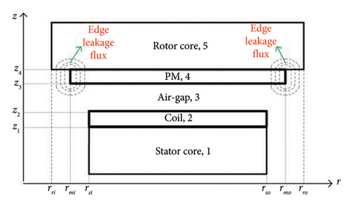
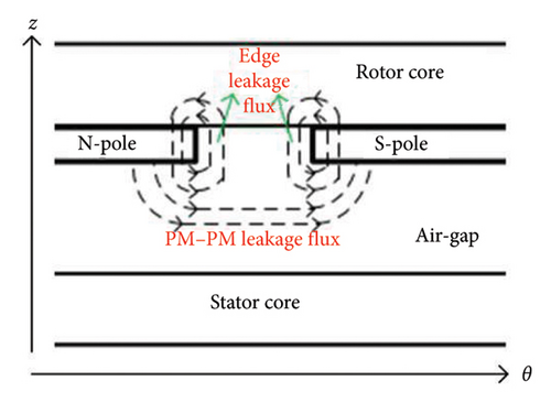
Laplace equation (1) is solved by using the variable separation method while assuming that the stator and rotor cores in the slotless AFPM machine have the infinite magnetic permeability. In Figure 2, the edge and overhang effects are due to the different radial lengths of domains. To accurately consider the geometrical variations in radial and tangential directions, the Fourier–Bessel series is used to represent the general solution of equation (1) in the ith domain, as shown in equation (7). j(k, l) in equation (7) is the kth root of the first-kind Bessel function Jl(r).
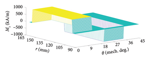
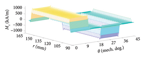
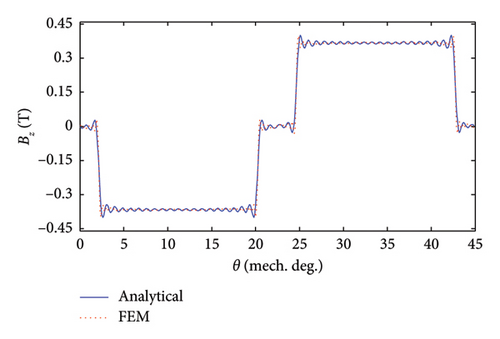
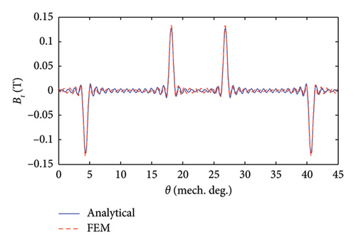
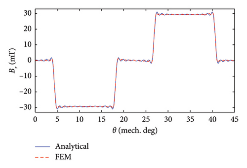
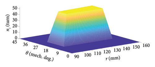
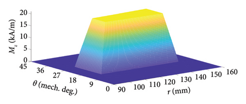
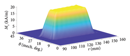
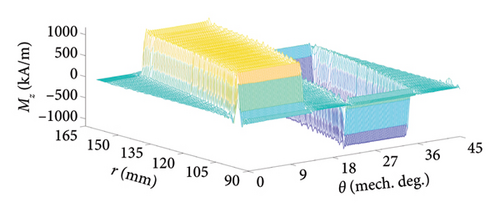
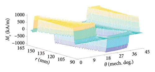
For the analyzed AFPM machine, the 2D turn function of one stator coil and the real and approximated distribution of Mz of corresponding virtual PM are shown in Figure 5 when assuming Ic = 1(A).
Similar to the no-load condition, the system of equation (15) is formed by applying the boundary condition at z = z1, z = z2, and z = z4 while removing the PM region in Figure 2.
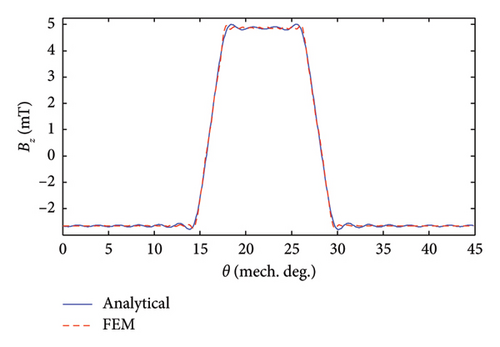
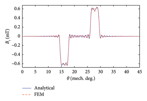
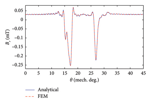
Under the excitation of Phase A with one ampere (IA = 1[A], IB = 0[A], IC = 0[A]), the components of air-gap flux density are shown and verified in Figure 6. The rationale behind choosing these specific current conditions is to calculate the self and mutual inductances of stator phases in the next section.
4. Flux Linkage Calculation
The 2D distribution of the turn function of the ith coil has been illustrated in Figure 5(a) while considering the distribution of conductors in the coil sides. The flux linkage with other stator coils can be easily calculated through shifting the result obtained from equation (17).
The calculation of phase flux linkage can be used to determine the elements of the inductance matrix while removing the PM poles. As shown in equation (19), nA(r, θ) is the 2D distribution of the turn function of Phase A and Bz(r, θ) is the 2D distribution of the main component of air-gap flux density due to the excitation of the relevant phase.
- 1.
The fundamental component and THD of phase flux linkage are reduced using the skewed PMs.
- 2.
The highest fundamental component and the highest THD of phase flux linkage have been obtained from the slotless AFPM machine with the circular PMs.
- 3.
The lowest THD of phase flux linkage has been obtained from the slotless AFPM machine including the trapezoidal PMs with the skew angle of 30°.
- 4.
The AFPM machine with the skewed trapezoidal PMs has more optimal phase flux linkage than it with the skewed rectangle PMs.
- 5.
In general, the slotless AFPM machine with the sinusoid PMs has more optimal phase flux linkage than others.

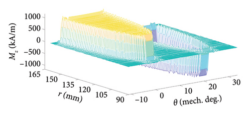

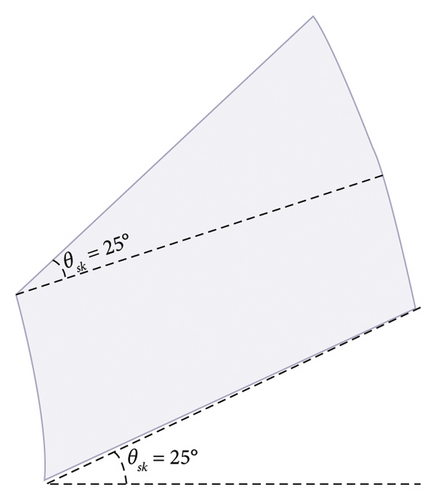
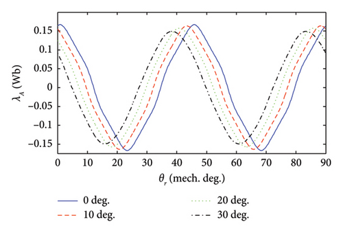
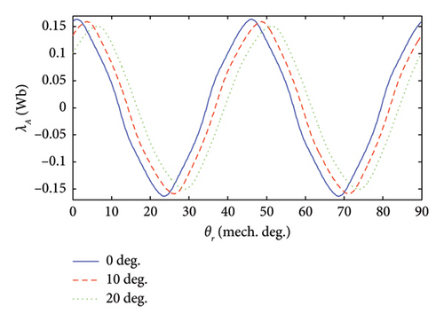
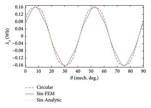
| PM shape | Skew angle | Fundamental component (Wb) | THD (%) |
|---|---|---|---|
| Trapezoid | 0° | 0.1555 | 5.24 |
| 5° | 0.1548 | 5.11 | |
| 10° | 0.1541 | 4.59 | |
| 15° | 0.1528 | 3.89 | |
| 20° | 0.1512 | 3.13 | |
| 25° | 0.1488 | 2.48 | |
| 30° | 0.1462 | 2.05 | |
| Rectangle | 0° | 0.1545 | 4.25 |
| 5° | 0.1536 | 3.88 | |
| 10° | 0.1521 | 3.54 | |
| 15° | 0.1497 | 3.37 | |
| 20° | 0.1461 | 3.42 | |
| 25° | 0.1416 | 3.51 | |
| Circular | — | 0.1691 | 5.5 |
| Sinusoid | — | 0.1548 | 3.9 |
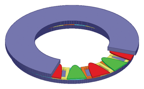
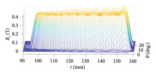
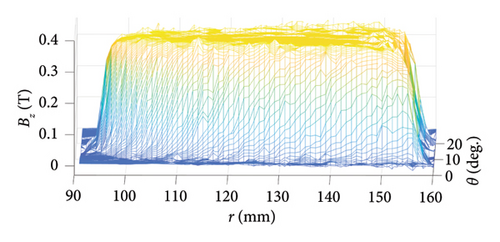
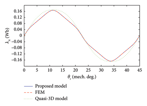
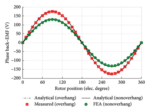
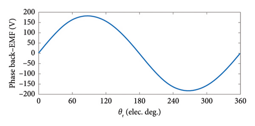
The 3D FEM model of the analyzed slotless AFPM machine with sinusoidal PM poles is shown in Figure 10. For this model of the analyzed AFPM machine, the capability and accuracy of the proposed 3D model for considering the edge effect have been shown and verified in Figure 11. In [19], the quasi-3D model based on the Hague solution has been used to calculate the z-component of air-gap flux density of the stator coreless AFPM machines. Figure 12 shows the high accuracy of the proposed 3D analytical model compared to the quasi-3D model. To verify with the experimental result, the phase back–EMF result of the manufactured slotless AFPM machine in [20] due to only PMs (dλA/dt) has been compared with the corresponding result obtained through the proposed 3D analytical model. As shown in Figure 13, there is a good agreement between both the results.
5. Conclusion
This paper proposed a new and fast 3D analytical model based on the scalar magnetic potential for electromagnetic analysis of the slotless AFPM machines. The geometry of the AFPM machine was divided into several domains, and the Laplace equation was solved in the air-gap region to determine the air-gap flux density components. To consider different PM shaping and skewing effects, the 2D distribution of PM magnetization was expressed in the Fourier–Bessel series. For this reason, the general solution of the Laplace equation was also expressed in the Fourier–Bessel series. The proposed approach was used to calculate the phase flux linkage while considering the PM shapes with or without the skewing effect. It was shown that the AFPM machine with skewed PMs has more sinusoidal phase flux linkage with a reduced fundamental component. Generally, it can be concluded that the AFPM machine with the sinusoidal PMs has more optimal phase flux linkage, which has low THD and high fundamental components, simultaneously. The proposed 3D analytical model can be extended to consider the slotting effect in future works.
Conflicts of Interest
The authors declare no conflicts of interest.
Funding
This research received no specific grant from any funding agency in the public, commercial, or not-for-profit sectors.
Open Research
Data Availability Statement
The data that support the findings of this study are available on request from the corresponding author. The data are not publicly available due to privacy or ethical restrictions.


