Segment Reduction-Based SVPWM Applied Three-Level F-Type Inverter for Power Quality Conditioning in an EV Proliferated Distributed System
Abstract
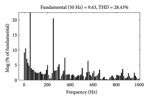
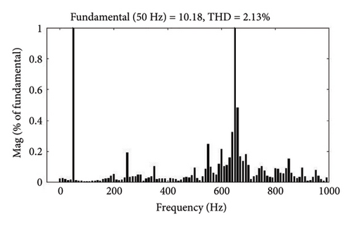
The objective of this paper lies in the realization of a three-level F-type inverter (3L-FTI) as a shunt active filter in an EV-proliferated environment. The switches are triggered using segment reduced space vector pulse width modulation (SVPWM). This modulation technique provides a lower number of switching transitions than existing PWM strategies. Consequently, the inverter switches experience a decrease in both switching stress and switching losses. A 3L-FTI is a diode-free structure that reduces the harmonics in the source current with a high power factor (PF), where instantaneous reactive power (IRPT) theory is employed to generate the reference currents from the utility grid. In contrast to traditional three-level inverters, two-thirds of switches in 3L-FTI can tolerate a voltage stress equal to half of the DC input voltage. While studying the behaviour of this shunt active filter, with three different nonlinear loading conditions, the current total harmonic distortion (THD) is reduced from 28.43% to 2.13% after compensation, which is under 5% of IEEE standard 519-2014. Therefore, the 3L-FTI controlled by segment reduction SVPWM can be considered as better candidate for active filter in an EV proliferated distribution system.
1. Introduction
Due to proliferation of electric vehicle (EV) and charging station integration [1, 2], the nature of current and voltage harmonics in the distribution system have emerged as major concerns. The battery charging units of electric vehicles have adverse effects on various components of power distribution system parameters including harmonic levels, voltage profile, power demand, and transformer power loss [3–6]. Increased levels of distorted current and voltage waveforms cause losses, overheating, reduce the operational life of distribution and instrument transformers [7], and ultimately result in the malfunction of delicate electrical equipment.
In motor drive systems, power converters with diode rectifiers are still used for driving the motor speed in a residential, commercial, and industrial tasks. Due to their nonlinear (NL) effects, diode rectifiers provide lower power losses, and significantly increase current harmonics. Low power quality, resonance, and finally stability problems with the distribution networks can be caused by the current harmonics [8, 9]. Battery EV (BEV) and Plugin hybrid EV (PHEV) obtain their power, either entirely or partially, from the utility grid, which consists of power converters. A wide range of semiconductor switches including diodes, thyristors and other semiconductor devices are utilized extensively to regulate the electric power supplied to loads. The integration of EV charging system contributes NL loading effects on the distribution system. Therefore, it is essential to minimize the effects of EV charging on the distribution grid [10, 11].
The literature [12–16] recommends the implementation of shunt active power filter (SAPF) to mitigate any adverse consequences induced by these bidirectional AC/DC converters. These solid-state converters, functioning as NL loads (NLLs), handle the reactive power and harmonics supplied by AC mains. They also generate unbalanced currents and consume a huge amount of neutral line current from the distribution grid. Previously, in order to mitigate harmonics, passive filters have been utilized. In addition to size, fixed frequency and resonance, passive filters have many drawbacks. In terms of implementing vital solutions to PQ issues, bidirectional AC/DC converters have been forced to address the seriousness of harmonic disturbances in electric grids. In such a case, APF can be a good candidate to address the issues.
A SAPF control method generally comprises of two components: voltage/current controller and the mechanism for generating the reference current. The reference [17] investigates the ability of EVs to manage voltage imbalances by adjusting their charging current in response to voltage measurements in the vicinity. The article [18] suggests a thorough way to look at energy and power to see if the vehicle-to-grid (V2G) mechanism can serve the purpose of reducing power quality (PQ) problems. This type of V2G solution may pose a significant obstacle for smart grid systems. In [19], an efficient model predictive control (MPC) technique is described with a T-type three-level neutral point clamped (NPC) inverter based SAPF. This three-level inverter necessitates eight switches per phase. A finite-set MPC was implemented for a SAPF utilizing two parallel inverters that shared the same dc-link, as described in article [20]. Utilization of two interleaved inverter sets, which requires PWM generation for the above mentioned parallel inverters, is a significant limitation of this method. The paper [21] provides implementation of distributed generation (DG) units powered by renewable energy sources in residential zones. These units have the potential to alleviate power quality issues associated with harmonics.
Reducing the THD of terminal voltage and current of grid-tied inverter poses a significant challenge for researchers. For the generation of PWM signals, to drive the SAPF, numerous PWM approaches were described in [22–24]. Space vector modulation (SVM) techniques were widely applied in the advanced control of shunt PQ compensation devices in distribution systems. The paper [25] evaluates a NPC three-level inverter as SAPF in accordance with space vector pulse width modulation (SVPWM). The literature [26] discusses a hysteresis control-based PWM approach for three-level inverters in addition to MPC. Integrated hysteresis current control and SVPWM were utilized to regulate the NPC inverter in this case. Another method for reducing harmonics is to use reference current generation-based control algorithms. SRF (dq) and (pq) theory have been applied in paper [27] to create a dual fundamental component extraction algorithm for the fundamental component of load current for a three-level inverter.
In contrast, since it is observed that EVs generate harmonic content that fluctuates in phase, cluster charging may result in harmonic cancelation and a smoothing effect to enhance perception of EV charging behaviour. The EV charging profile and waveforms (EV-CPW) dataset for AC (level 1 and level 2) charging is presented in paper [28]. The database consists of charging profiles and high-resolution AC current and voltage waveforms associated with 12 distinct electric vehicles. In order to address power quality concerns arising from the fluctuating characteristics of electric vehicle charging, specific devices may be necessary, such as APFs, which are designed to eliminate harmonics [29–31]. A modular, three-level SAPF with a self-adaptive active damping control technique was proposed in the study [32]. A hybrid approach combining Gramian angular summation field (GASF) method with a convolutional neural network (CNN) has been presented in paper [33], to classify power quality disturbances.
Still, accuracy of the system in steady state decreases as a result of repeated controller actions and grid frequency variations. In article [34], SAPF is a combination of distinct kinds of inverter modules with various switching frequencies, LCL filter ranges, and current ratings. The system is bulky due to the use of large components on the supply side of the filter.
Thus, the present work investigates a new segment reduced SVPWM algorithm for 3L-FTI [35] as SAPF for an EV-proliferated distribution system. The inverter used in the above system has been constructed to meet the standards (IEEE 519-2014) of current harmonics in a distribution network. This system is capable of producing the desired compensation current while simultaneously verifying the efficient working of a SAPF, even under the influence of a nonlinear load, without using any huge filter requirements. A simulation study using MATLAB/Simulink and an experiment using an FPGA processor are used to confirm the design idea and the proposed segment reduced SVPWM algorithm’s effectiveness. The rest of the paper is organized as follows: Section 2 describes a brief overview of 3L-FTI and its system configuration, and Section 3 describes the reference current generation of 3L-FTI. Section 4 contains a detailed description of the segment reduced SVPWM switching algorithm. Section 5 discusses the simulation and experimental results, respectively. Finally, the conclusion is presented in Section 6.
2. System Description
Similar to numerous studies in the field, this paper employs a three-level structure for the DC/AC converter in order to provide power conditioning for EV-proliferated distribution networks, specifically for the purpose of harmonic compensation of NL loads [36, 37]. Figure 1 illustrates the medium voltage distribution system, which includes linear, NL, and EV loads connected at the PCC.
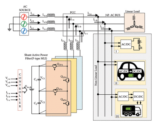
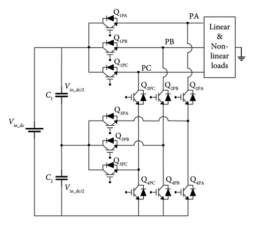
A 3L-FTI is connected at PCC, which is functioning as a SAPF in this system, as seen in Figure 1. The SAPF primarily restores source currents (Is−a, Is−b and Is−c) that have been degraded by the NLLs currents. When compared to conventional inverters which have only two levels, the multilevel inverter offers an array of functions such as less voltage and current harmonics. The suggested 3L-FTI topology is comprised of 12 switches without clamping diodes. Figure 2 depicts the structure of 3L-FTI. Each phase consists of four semiconductor switching devices, such as Q1PA − Q4PA, Q1PB − Q4PB, and Q1PC − Q4PC, respectively. The 3L-FTI utilizes a shared supply voltage between two dc-link capacitors (C1 and C2) with identical capacitance voltage Vin_dc/2. With both the Q1PA and Q3PA switches in the on position, the output value is +Vin_dc/2. A −Vin_dc/2 output is produced when the switches Q2PA and Q4PA are switched on. When switches Q2PA and Q3PA are turned on, the output level is zero. The switching states of an inverter for phase A (PA) are illustrated in Table 1, along with the active switches for each state. The values 1, 0, and −1 in this table correspond to the positive, zero, and negative voltage levels of the inverter.
| Switching state | Active switches in phase A (PA) | In-active switches in phase A (PA) | Load voltage/phase |
|---|---|---|---|
| 1 | Q1PA, Q3PA | Q2PA, Q4PA | +Vin−dc/2 |
| 0 | Q2PA, Q3PA | Q1PA, Q4PA | 0 |
| −1 | Q2PA, Q4PA | Q1PA, Q3PA | −Vin−dc/2 |
2.1. Switching Transitions
Regardless of current direction, the switches need to be switched at the correct time for the phase current to flow exactly in the respective branch. There are three possible pathways for the current to flow from the dc voltage link to the load. Figures 3(a), 3(b), and 3(c) depict the direction of current flow in the inverter mode in PA. When Q1PA and Q3PA are switched on to follow a symmetrical pattern of switching, Q3PA remains inactive. Based on this, the voltage stresses on lower arm switches are less during conduction period.
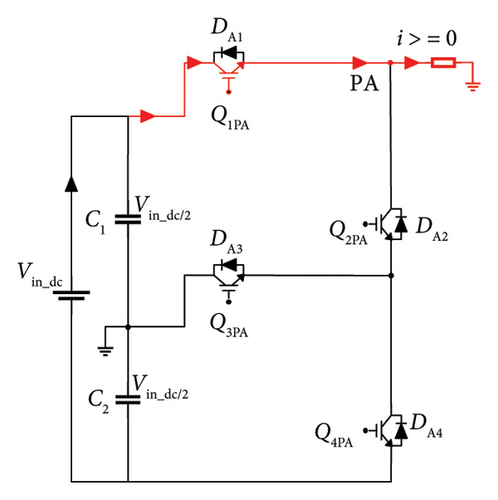
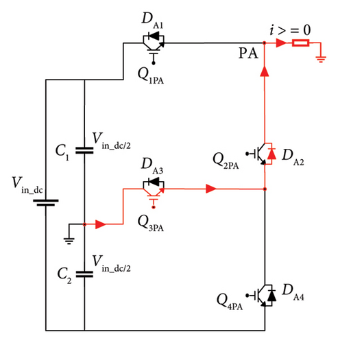
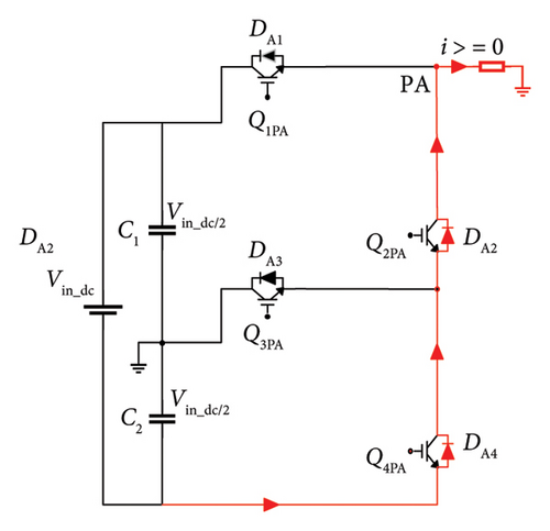
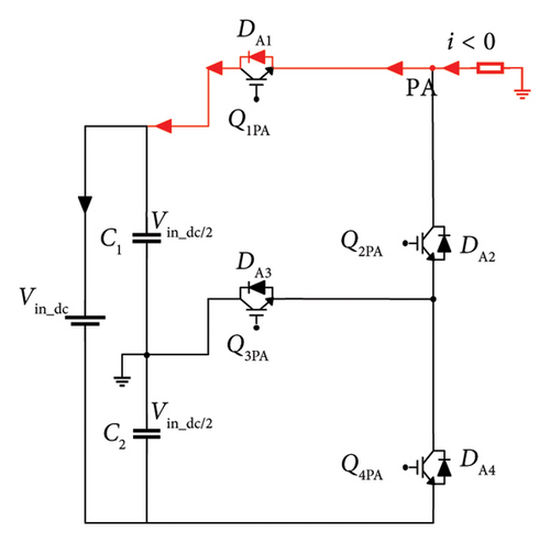
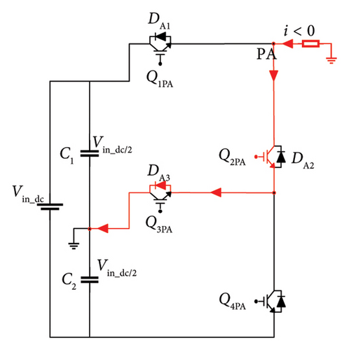
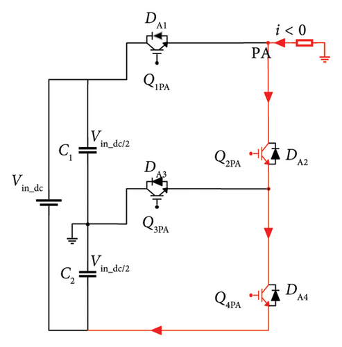
The required switch rating for the presented inverter is 0.5 times lesser in lower arm when compared to the rating of upper arm switches. During this mode, the line current is positive (i > 0). The recommended 3L-FTI operates in bidirectional mode namely in rectification and in inverter modes. Figures 3(d), 3(e), and 3(f) show the current flow direction from load to dc voltage link. The line current is negative (i < 0), and the converter operates in rectification mode. Table 2 outlines the switching sequence of the inverter to derive line-line and line-neutral output voltage of 3L-FTI.
| Switches | Switching devices of phase A | Switching devices of phase B | Switching devices of phase C | VAN | VBN | VAB | |||||||||
|---|---|---|---|---|---|---|---|---|---|---|---|---|---|---|---|
| Sector | Q1PA | Q2PA | Q3PA | Q4PA | Q1PB | Q2PB | Q3PB | Q4PB | Q1PC | Q2PC | Q3PC | Q4PC | |||
| I | On | Off | On | Off | Off | On | Off | On | Off | On | On | Off | +Vin−dc/2 | −Vin−dc/2 | Vin−dc |
| II | On | Off | On | Off | Off | On | On | Off | Off | On | Off | On | +Vin−dc/2 | 0 | +Vin−dc/2 |
| III | Off | On | On | Off | On | Off | On | Off | Off | On | Off | On | 0 | +Vin−dc/2 | −Vin−dc/2 |
| IV | Off | On | Off | On | On | Off | On | Off | Off | On | On | Off | −Vin−dc/2 | +Vin−dc/2 | −Vin−dc |
| V | Off | On | Off | On | Off | On | On | Off | On | Off | On | Off | −Vin−dc/2 | 0 | −Vin−dc/2 |
| VI | Off | On | On | Off | Off | On | Off | On | On | Off | On | Off | 0 | −Vin−dc/2 | +Vin−dc/2 |
3. Instantaneous Reactive Power (IRPT)-Based Reference Current Generation for 3L-FTI
The distribution grid PQ is improved by grid-connected SAPFs via the control algorithm illustrated in Figure 4. In order to produce a reference current under unbalanced voltage conditions, the IRPT-based control technique is suggested for this system. Additionally, it should be noted that the segment reduced PWM control method has been designed to maintain the sinusoidal grid current, regardless of irregular grid voltages, distorted load current, or electric vehicle charging and discharging current.
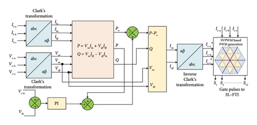
These currents are compared with the actual source currents (Is−a, Is−b, Is−c), as illustrated in Figure 4.
4. Segment Reduced SVPWM Control on 3L-FTI
Assuming, subsector one of sector I contains Vr.
Determination of three nearest switching vectors for subsector one is as follows:
The voltage vectors denoted with a, b, and c represent the closest values for the inner triangle of sector I, subsector 1, as illustrated in Figure 5. The calculation for voltage vector ‘a’ is as follows: where V01, V02, and V03 represent the redundant voltage vectors associated with this node.
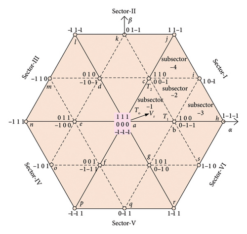
The redundant voltage vectors denoted as V21 and V22 belong to node ‘b’ within sector I, subsector 1.
The redundant voltage vectors denoted as V11 and V12 are specified for the node ‘c′ within sector I, subsector 1.
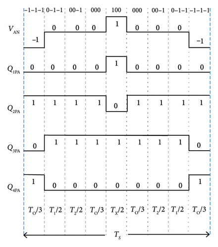
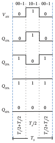
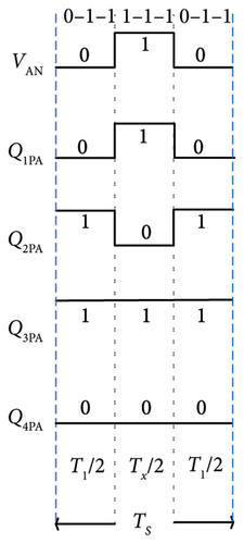
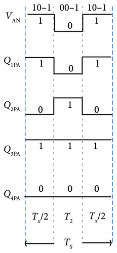
As shown in Figure 5, the standard switching sequence of ABC from sector-I, subsector 1 is (–1–1–1) – (0–1–1) – (00–1) – (000) – (100) – (110) – (111) – (111) – (110) – (100) – (000) – (00–1) – (0–1–1) – (–1–1). It consists of 14 alternating segments. By removing the redundant voltage vectors (110) – (111) – (111) – (110) – (100) from the 14 segment switching sequence, the modified nine-segment SVPWM method has been developed, which is illustrated in Figure 6a. Following is the sector switching sequence for subsector 2, which contains the reference voltage (Vr): (0–1–1) – (00–1) – (10–1) – (100) – (110) – (110) – (100) – (10–1) – (00–1) – (0–1–1). After removing the redundant vector, the resulting vector sequence consists of three segments: (00–1) – (10–1) – (00–1) as shown in Figure 6(b). If Vr is located in subsector 3, their eight-segment switching sequence becomes (0–1–1) – (1–1–1) – (10–1) – (100) – (100) – (10–1) – (1–1–1) – (0–1–1). By applying segment reduction, this array of sequence can be reduced into a three-segment model. Figure 6(c) shows a simplified switching sequence consisting of three segments from subsector 3.The reference voltage vector (Vr) for subsector 4 is made up of eight segments that make up the exact switching sequence, which is denoted by (110) – (11–1) – (10–1) – (00–1) – (00–1) – (10–1) – (11–1) – (110). The evolution for a refined three-segment SVPWM sequence for subsector four is illustrated in Figure 6(d). Table 3 presents the performance comparison of conventional and segment reduced SVPWM for a 3L-FTI with an RL load. For this investigation, the frequency and amplitude modulation indices are 100 and 0.9, respectively.
| Parameters | Conventional SVPWM | Segment reduced SVPWM |
|---|---|---|
| Current harmonics (%) | 16.44 | 14.89 |
| Voltage harmonics (%) | 36.17 | 31.64 |
| Total power loss (watts) | 53.95 | 44.53 |
| Neutral point fluctuation (%) | 0.22 | 0.16 |
| Fluctuation between two capacitor voltages (volts) | 88 | 64 |
5. Performance Verification of 3L-FTI With NL Loads
This section presents performance evaluation of IRP theory-based segment reduced SVPWM control structure for 3L-FTI. The NL condition is selected to analyse in three different scenarios. The comparative performances are verified, and studies are carried out using MATLAB/Simulink and real-time systems, respectively.
5.1. Simulation Result Analysis
To investigate the impact of EV charging stations on the distribution system, a simulation model of proposed SAPF and control algorithms is created and tested in MATLAB/Simulink.
The design parameters, such as distribution grid supply voltage, load output voltage ratings are presented in Table 4. It has been tested with harmonic analysis for different load conditions.
| Parameters | Simulation | Experimental | |
|---|---|---|---|
| AC distribution line voltage | VRMS(LL) | 415 V | 100 V |
| Frequency of grid | fs | 50 Hz | 50 Hz |
| DC link voltage | Vin−dc | 400 V | 100 V |
| DC link capacitors | C1, C2 | 1000 μF | 100 μF |
| Filter inductance | Lf | 5 mH | 2 mH |
| Switching frequency | fs | 5 kHz | 5 kHz |
-
Case 1: NL-RL load
-
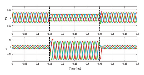
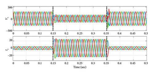
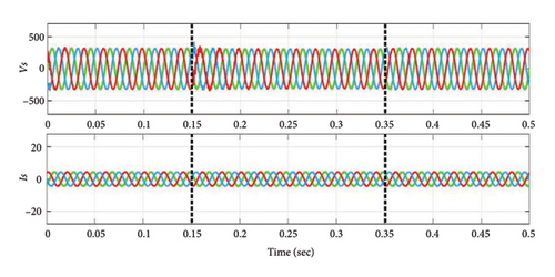
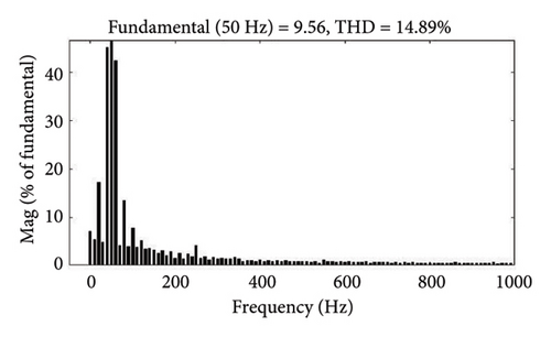
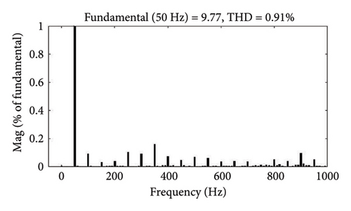
In this instance, a three-phase diode bridge rectifier supplying a series-connected 50 Ω resistor and a 2 mH inductor constitutes the NL-RL load. Considering this NL-RL load condition, disturbance is applied between 0.15 s and 0.35 s, the performance of VS, IS, VL, and IL before power quality conditioning is depicted in Figures 7(a) and 7(b). During this period, the load demand increases. In this case, the segment reduced 3L-FTI effectively decreases the THD of source currents (IS−a, IS−b, and IS−c), as demonstrated by the results in Figure 7(c). Before and after PQ correction, Figures 7(d) and 7(e) show the FFT analysis of the three-phase source currents (IS) for Case 1. According to the data presented in Table 5, the source current THD values have decreased from 14.89% to approximately 0.91%, thereby meeting IEEE standard 519–2014.
-
Case2: NL-level-1 battery as load
-
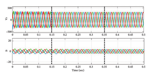
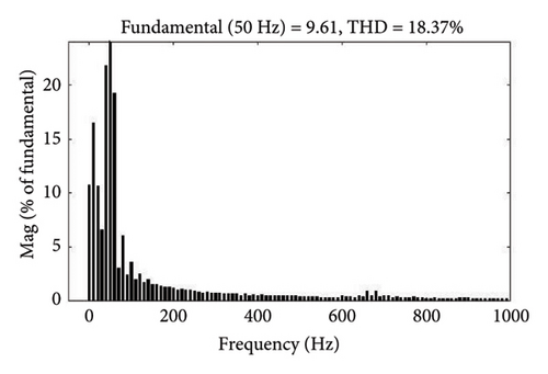
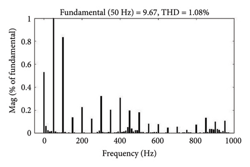
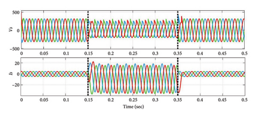
In Case 2, the SAPF system operates with EV battery (50 Ah) as NL-level (1) load for a duration of 0.15 s to 0.35 s. The voltage and current profiles, including VS, IS, VL, and IL, are shown in Figures 8(a), and 8(b). Integrating the SAPF, as illustrated in Figure 8(c), maintains the source voltage and current. Before compensation, the generated current THD during 0.15 s–0.35 s is around 18.37%. With the suggested controller, it drops to 1.1% and source current becomes sinusoidal. Figures 8(d) and 8(e) show the FFT analysis of source current before and after compensation.
-
Case3: NL-level-3 battery as load
-
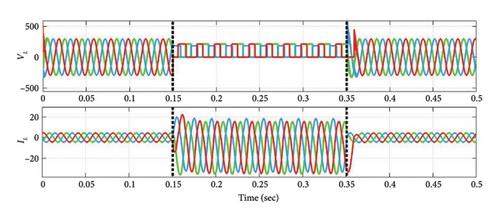
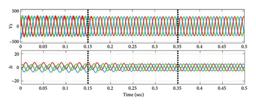
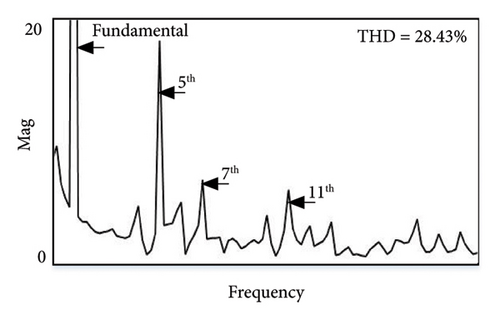
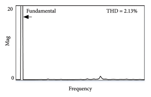
The simulation results for NL-level (3) battery (150 Ah) load are displayed in Figures 9(a), and 9(b), with addition of battery load during 0.15 s–0.35 s. As the compensation current is applied at the PCC during above said time, THD value is almost reduced to 2.13% in all phases from 28.43% shown in Figure 9(c). Similarly, the FFT spectrum of current THD value of the system is presented in Figures 9(d), and 9(e). Three case studies are compared for the prominent harmoniecs before and after power quality correction for Vs and Is, respectively, as shown in Table 5.
| Load conditions | 3rd | 5th | 7th | 9th | 11th | THD% | 3rd | 5th | 7th | 9th | 11th | THD% |
|---|---|---|---|---|---|---|---|---|---|---|---|---|
| Current THD (before compensation) | Voltage THD (before compensation) | |||||||||||
| Case1 | 2.47 | 1.52 | 0.69 | 0.92 | 0.68 | 14.89 | 1.3 | 23.99 | 10.58 | 1.64 | 10.22 | 31.64 |
| Case2 | 1.29 | 0.82 | 0.55 | 0.39 | 0.24 | 18.37 | 8.63 | 5.57 | 0.71 | 2.85 | 0.44 | 43.94 |
| Case3 | 5.44 | 3.71 | 4.55 | 1.30 | 1.22 | 28.43 | 13.48 | 8.32 | 2.12 | 5.82 | 3.71 | 47.28 |
| Current THD (after compensation) | Voltage THD (after compensation) | |||||||||||
| Case1 | 0.12 | 0.1 | 0.16 | 0.07 | 0.06 | 0.91 | 0.53 | 0.14 | 0.36 | 0.35 | 0.16 | 3.2 |
| Case2 | 0.13 | 0.12 | 0.2 | 0.19 | 0.08 | 1.1 | 0.84 | 1.28 | 1.15 | 2.08 | 1.03 | 4.12 |
| Case3 | 1.15 | 18.1 | 6.93 | 1.81 | 1.31 | 2.13 | 2.72 | 1.21 | 2.33 | 3.87 | 1.55 | 4.66 |
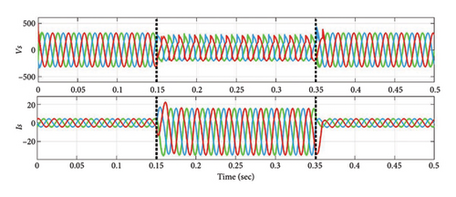

Thus, it can be inferred from the examples discussed in above three cases, the SAPF system responds effectively to varying NL loading situations for RL and EV charging batteries. In compliance with IEEE standard 519, the suggested method simultaneously reduces the source current THD in all three scenarios.
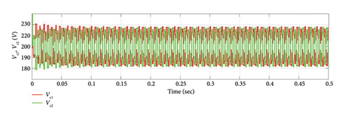
Figure 10 shows the voltage across DC link capacitors C1 and C2 with a switching frequency of 5 kHz. The comparative findings based on the structure of three-level inverter-based shunt APFs are summarized in Table 6. This table clearly shows that, when compared to the existing control algorithms, the suggested segment reduced SVPWM with 3L-FTI inverter based SAPF operates with reduced THD values of source current, demonstrating the improved performance of the recommended SAPF system.
| Features | [19] | [25] | [26] | [27] | [32] | [33] | Proposed system |
|---|---|---|---|---|---|---|---|
| Topology | 3L-T-type as SAPF | 3L-NPC as SAPF | 3L-NPC as SAPF | 3L-NPC as SAPF | 3L-NPC as SAPF | 3L-NPC as SAPF | 3L-FTI as SAPF |
| Switches/leg | 8 | 4 | 4 | 4 | 4 | 4 | 4 |
| Diodes/leg | — | 2 | 2 | 2 | 2 | 2 | — |
| Inductors/leg | — | — | — | — | 2 | 2 | — |
| Capacitors/leg | — | — | — | — | 1 | 1 | — |
| Control algorithm | Model predictive control | SVM | Hysteresis current control | SVPWM | Resonance control | Self-adaptive active damping | Segment reduced SVPWM |
| % THD | Not mentioned | 4.1 | 4.57 | 2.8 | 6.009 | 4.89 | 2.12 |
5.2. Experiment Result Analysis
In this section, the experimental results obtained for the segment reduced SVPWM based 3L-FTI applied SAPF system. The parameters of the scale down experimental testbed are shown in Table 4, and the setup is presented in Figure 11. The effectiveness of the proposed system is validated using 10 Ah and 30 Ah battery ratings in the laboratory. An AC bus with RL and battery loads emulates NL load. The Spartan 6 controller FPGA module is utilized to implement the proposed PWM algorithm for 3L-FTI. A four-channel digital oscilloscope is used to capture the results, and harmonic analysis is performed. Loads consist of a three phase diode bridge rectifier with an RL load, level-1 battery load, and level-3 battery load on PCC.
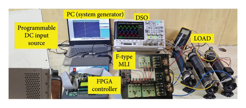
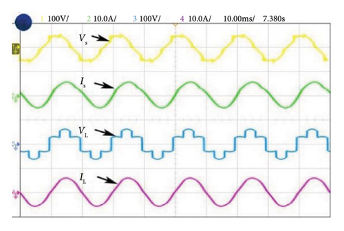
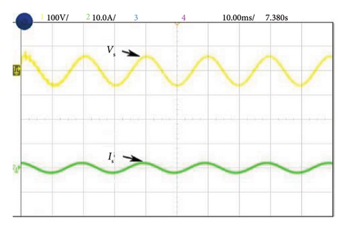
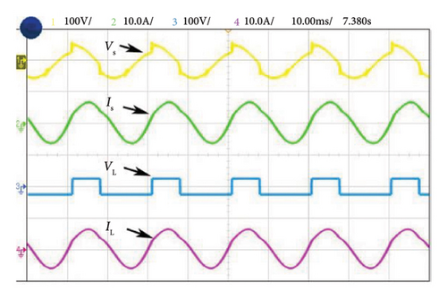
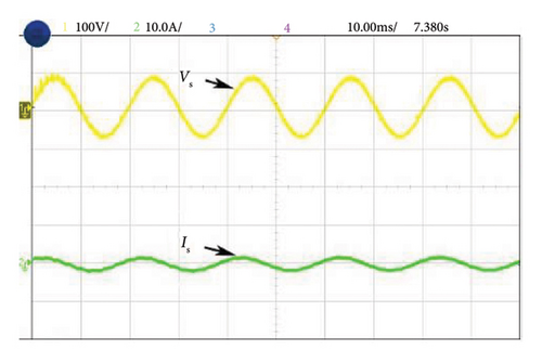
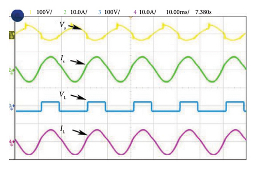
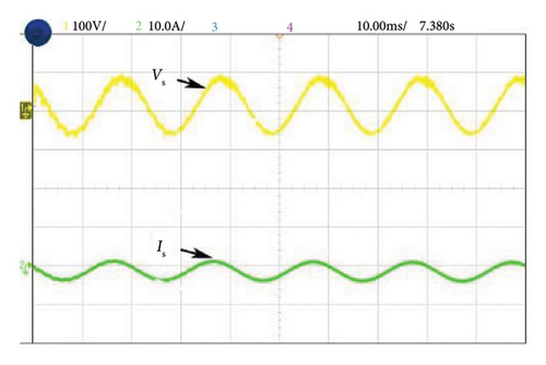
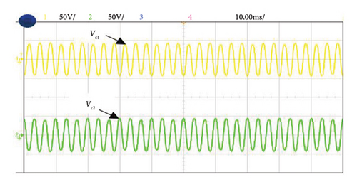
Figure 12(a) illustrates the harmonic current and voltage in the distribution system during Case 1 of NL loading such as RL load before introducing the shunt active filter. The source and load voltages of Case 1 after compensation are shown in Figure 12(b). Here, source current is balanced and the THD is reduced and maintained at a level of 0.91%. Figures 13(a) and 13(b) illustrate the experimental performance analysis of SAPF system with proposed controller under Case 2. Here, source current THD is considerably reduced up to 1.1% of its rated value. Similarly in Case 3, a current THD of 2.13% is obtained as shown in Figure 14(a), and 14(b). The voltages Vc1 and Vc2 are measured across the DC link capacitors C1 and C2, respectively, as depicted in Figure 15.The FFT spectrum analysis for Case 3 with NL loading conditions are shown in Figures 16(a), and 16(b). With desired results obtained for source current and source voltage by SAPF, this system proves to be an effective and efficient power quality conditioning device.
6. Conclusion
This paper focuses on the application of 3L-FTI as a SAPF in a three-phase four-wire system. A new segment reduced SVPWM algorithm is incorporated to generate triggering pulses for the IGBT switches in 3L-FTI. As the research focus is on realizing the segment reduced SVPWM 3L-FTI as SAPF in an EV proliferated environment, a conventional IRPT control algorithm is implemented to generate the reference current. MATLAB/Simulink-based rigorous simulative analysis for the proposed SAPF system is carried out under different NL loading conditions. The percentage of THD recorded for each case of compensated source current (Is) is as follows: THD for NL resistive-inductive load is 0.91%, THD for NL-level 1 battery load is 1.08%, and the THD for NL-level 3 battery load is 2.13%. The THD of observed current on varying load conditions are below 5% which is in accordance with IEEE Standard 519-2014. Furthermore, the experimental outcomes confirm the effective performance of segment reduced SVPWM 3L-FTI as SAPF.
Nomenclature
-
- EV
-
- Electric vehicle
-
- NL
-
- Nonlinear load
-
- PQ
-
- Power Quality
-
- THD
-
- Total harmonic distortion
-
- SAPF
-
- Shunt active power filter
-
- 3L-FTI
-
- Three-level F-type inverter
-
- PF
-
- Power factor
-
- SVPWM
-
- Space vector pulse width modulation
-
- IRPT
-
- Instantaneous reactive power theory
-
- MLI
-
- Multilevel inverter
-
- BEV
-
- Battery electric vehicle
-
- PHEV
-
- Plugin hybrid electric vehicle
-
- APF
-
- Active power filter
-
- LPF
-
- Low-pass filter
-
- V2G
-
- Vehicle to grid
-
- MPC
-
- Modern predictive control
-
- DG
-
- Distributed generation
-
- NPC
-
- Neutral point clamped
-
- EV-CPW
-
- EV charging profile and waveforms
-
- PCC
-
- Point of common coupling
-
- NLLs
-
- Nonlinear loads
-
- RL Load
-
- Resistive inductive load
-
- NL-RL Load
-
- Nonlinear-RL Load
-
- FPGA
-
- Field programmable gate array
-
- IGBT
-
- Insulated gate bipolar transistor
Conflicts of Interest
The authors declare no conflicts of interest.
Author Contributions
All authors planned the study and contributed to the idea and field of information; introduction, M.M.; methodology, M.M. and C.N.; formal analysis, M.M.; writing–original draft preparation; M.M.; writing–review and editing, C.N., and R.C.B.; supervision, C.N.; and corresponding author, R.C.B.. All authors have read and approved the manuscript.
Funding
No funding was received for this research.
Acknowledgements
The authors would like to thank their universities for the support provided.
Open Research
Data Availability Statement
Data will be made available on suitable request.


