Active and Reactive Power Sharing Between Dispatchable Distributed Generation Units Within a Microgrid With Multiple Grid Interconnections, Using Enhanced Interconnection Flow Controller
Abstract
This paper discusses the enhancements made to the basic interconnection flow controller (IFC) design recommended for microgrids for managing active power flow on the interconnection lines between the microgrid and main grid. The enhancements focus on two key features: the frequency response balancing within the active power controller, and integration of the interconnection reactive power flow controller (IRFC). A microgrid, in grid interconnected mode, is defined to be ideal, when it either acts a constant load or as a constant source with reference to the main grid. The designed enhancements ensure that microgrid continue to operate ideally, not only with reference to the active power but also with regards to the reactive power flow from the main grid, even during minor frequency deviations in the main grid. The suggested modifications aim to maintain system stability by dynamically adjusting active and reactive power flows between the microgrid and the main grid. The simulation results show that the enhanced-IFC (e-IFC) outperforms the standard IFC, especially during varying reactive power demand and frequency deviation events. The proposed e-IFC achieves an 80% reduction in active power flow deviation (from ±10% to ±2%) and improves frequency recovery time by over 50% (from 6.5 to 3.2 s). Reactive power flow regulation is maintained within ±2% of reference under dynamic load conditions, ensuring voltage stability. The e-IFC’s ability to independently control both active and reactive power flows offers an ideal, more stable and efficient operation of the microgrid, improving overall system reliability.
1. Introduction
Microgrids are now emerging as key components of modern power systems, designed to operate either in grid-connected mode or in isolation mode. IEEE defines a microgrid as “A microgrid is a group of interconnected loads and distributed energy resources within clearly defined electrical boundaries that acts as a single controllable entity with respect to the grid” [1]. Interconnected microgrids should ideally function as a constant load or source for the main grid. One of the key challenges in achieving optimal microgrid operation is the intermittent nature of renewable energy sources. As the penetration of renewable sources increases, maintaining a constant power flow to or from the main grid becomes increasingly difficult. This challenge is further compounded for microgrids with multiple interconnections, where the complexity of managing power flow across several grid interfaces intensifies the issue. This ideal operating scenario can only be realized if the dispatchable and distributed generating units (DDGUs) within the microgrid are capable of fully compensating for fluctuations in local demand and generation. Variability in local generation or demand may arise from the variance in the load, intermittency of renewable, Non-DDGUs (NDDGUs), or from partial or complete outage of any generation source. Achieving optimal operation becomes even more challenging for microgrids with higher levels of renewable penetration and fluctuating loads/demand compared to those with lower renewable penetration and more stable load profiles.
Challenges such as frequency deviations and reactive power imbalances can severely impact the performance and reliability of these systems. The proliferation and integration of variable renewable energy sources have introduced new challenges related to almost every aspect of microgrids operations and stability. Ensuring stable power flow and system reliability requires effective control mechanisms, particularly for balancing active and reactive power and maintaining frequency.
Researchers have been studying to mitigate these challenges for a long time. For active and reactive (P&Q) power control and management within a microgrid several techniques are presented in the literature. All recent contributions in this area are mainly focused towards either the internal voltage control of a microgrid or the economic dispatch of the DDGUs. In all the recent referenced publications, microgrid with one connection to the main grid was considered.
The research presented in [2] proposed a novel bi-level optimization model for combined cooling, heating, and power (CCHP)-dominated integrated community energy systems (ICESs) in the day-ahead distribution electricity market (DEM). The model introduced a new trading mechanism between ICES operators (ICESOs) and the distribution system operator (DSO) to optimize both active and reactive power scheduling. The proposed model enhances the operational efficiency of ICESs by enabling optimized power scheduling and effective integration of distributed energy resources.
In [3], an enhanced control strategy for microgrids integrating renewable energy sources is proposed. It utilizes a finite control set-model predictive control (FCS-MPC) approach, which is designed for both islanded and grid-connected operational modes. The proposed control strategy includes voltage control, power sharing, and negative-sequence current control loops to ensure system stability and efficiency in both modes. By reducing computational demand and minimizing inverter switching, the control method enhances system performance in terms of voltage regulation, power quality, and harmonic reduction. A similar MPC-based method for dynamic control and optimization of distributed energy sources within a microgrid is presented in [4].
A predictive control-based algorithm is proposed in [2] for achieving optimal energy management (OEM) in renewable-based hybrid microgrids (HMGs). This method consisted of a modified model predictive control-based improved Firefly1to3 algorithm (MMPC-IFA1to3). Using this method, active and reactive power references were generated, resulting in simpler switching operations in voltage source converters. This research focused mainly on active and reactive power management through objective function minimization. The proposed IFA1to3 was demonstrated to minimize costs, ensure power availability, and mitigate voltage deviations in renewable-based HMGs.
Parallel operation of voltage source converters and synchronous generators within a microgrid is studied in [5] and a droop-based frequency control is recommended. The research proposed a supervisory center controller to ensure stable system frequency.
A comprehensive comparison and review of reactive power sharing methods within microgrids operating in islanded mode is provided in [6, 7]. The paper presented a review of the recommended communication-less reactive power sharing approaches recommended in referenced literature. The comparative analysis concluded that the new methods are all improvements to the traditional Q/V droop method and are greatly sensitive to the network configuration and other network parameters.
An improved VSG control algorithm based on fuzzy logic algorithm is proposed in [7]. This integrated control algorithm of power distribution is recommended for islanded microgrids.
In [8], a centralized reactive power sharing method is discussed for isolated microgrids. The proposed method is shown to be resilient to the communication link failures, which are the main cause of the reactive power sharing error and subsequent voltage instability of the microgrid. An adaptive virtual impedance control was used in a centralized manner under normal operating conditions, while in case of communication link failure, a centralized/decentralized control method is recommended.
A method for optimizing power flow in distribution networks that integrate multiple microgrids is presented in [9]. The research introduced a Multi-Actor-Attention-Critic (MAAC) deep reinforcement learning approach, designed to solve the challenges of dimensionality explosion in high-dimensional optimization problems. The proposed method focuses on balancing active and reactive power within large-scale non-convex environments, ensuring system stability, reducing network losses, and improving computational efficiency. Additionally, the paper incorporates transfer learning to enhance the adaptability of the optimization algorithm in dynamic operational scenarios, such as grid topology changes or device switches. The paper focused on optimizing power flow within a single grid environment that integrates multiple microgrids with one grid interconnection.
As another example of a dynamic droop controller [10], proposed an advanced control strategy for managing the power flow between AC and DC subgrids in HMGs. The traditional normalized droop control, while useful for bidirectional power coordination, often leads to issues such as power transmission inaccuracies and voltage deviations from rated values, especially under varying load conditions. To address these challenges, the research introduced an adaptive droop control method that dynamically adjusts the droop coefficient based on real-time system conditions. Similar to all others mentioned above, this research also considered a microgrid with a single grid connection.
The paper [11] proposed a data-driven strategy for coordinated Volt/Var control (VVC) in active distribution networks (ADNs) with multiple microgrids. This strategy aimed to ensure secure and efficient operation despite the presence of false data injection attacks (FDIAs). The approach utilized convolutional neural networks (CNNs) to emulate the behavior of microgrid central controllers (MGCC). A voltage sensitivity-based reactive power adjustment method is also proposed to streamline the iterative optimization process. To protect data integrity and security, the paper integrated encryption algorithms (GGH and RSA) into the communication process between microgrids and DSOs. This technique is based on the communication-based controller considering microgrids with single interconnections.
A control and power management system (CAPMS) for hybrid PV-battery microgrids that operates in both grid-connected and islanded modes is presented in [12]. This study emphasized the real-time control of both AC and DC bus voltages and ensured a smooth transition between operational modes. By integrating maximum power point tracking (MPPT) and dynamic battery management, the system maintains power balance and stability even during fluctuations in solar irradiance or load demand. Additionally, CAPMS enabled flexible power flows and voltage regulation across various operating scenarios. The research provided a method to control power delivery within a hybrid inverter either in islanded or grid connected mode. A similar technique is proposed in [13] but only for isolated microgrids. The paper presented a decentralized power management and load-sharing method for a photovoltaic (PV)-based islanded microgrid consisting of various PV units, battery units, and hybrid PV/battery units. The proposed method considered available PV power and battery conditions of the units to share the load among them.
A voltage control strategy for an integrated medium- and low-voltage distribution network based on active-reactive power coordination optimization is proposed in [14]. It established an integrated control model for the medium- and low-voltage distribution network, taking voltage offset and network loss as the optimization objectives. The method utilized reactive power compensation devices and active power control of energy storage systems (ESS) as control variables. The proposed strategy claimed to effectively solve the problem of voltage overrun in the distribution network by coordinating the active and reactive power of the medium- and low-voltage systems.
A comprehensive comparison of the proposed active and reactive power strategies is presented in [15], while [16] detailed various control mechanisms, including droop control, MPC, and multi-agent systems (MAS). The research addressed the increasing integration of renewable energy sources into microgrids and the associated control challenges. It reviewed state-of-the-art control strategies and trends, classifying microgrid control into three hierarchical levels: primary, secondary, and tertiary. These levels manage microgrid operations, from internal controls to coordination with the larger power grid. It is noted that none of the strategies reported in these technology reviews [15, 16] were focused on the interconnection flow, as almost all of the quoted research papers were focused on microgrids with single grid connection.
Interconnection flow controllers (IFCs), crucial for managing power flows in interconnected grids, face notable limitations. High initial costs and complex installation requirements pose significant barriers, particularly for smaller or resource-constrained grids. Additionally, IFCs struggle with flexibility, often failing to adapt quickly to dynamic changes in grid conditions such as fluctuating renewable energy outputs. This technological rigidity, combined with scalability challenges and potential cybersecurity vulnerabilities, necessitates cautious integration and ongoing assessment to ensure grid stability and efficiency.
- •
Balancing active power flow and frequency response controller.
- •
IRFC.
The rest of the paper is organized as follows: Section 2 has the methodological approach, Section 3 presents the simulation results for balancing the enhanced-IFC (e-IFC), Section 4 talks about the IRFC, Section 5 presents the Simulation Results for the IRFC, and finally, Section 6 concludes the paper.
2. Methodological Approach
The following section with suitable subsections will demonstrate the considered methodological pathway considered in this research work with suitable conceptual illustration and mathematical formulation.
2.1. Design Enhancements
- •
Balancing active power flow and frequency response controller.
- •
IRFC.
2.1.1. Balancing Active Power Flow and Frequency Response Controller
Figure 1 displays the upgraded IFC’s control block diagram. Frequency response control in a grid interconnected microgrid is designed to maintain system stability by adjusting the active power output from DDGUs when the grid’s frequency deviates from its nominal value.

When grid frequency increases: If the frequency of the main grid rises above the set deadband (the allowable range of frequency deviation before corrective action is taken), it indicates an oversupply of power. The frequency response control will react by trying to reduce the active power output from DDGUs to help balance the overall power supply.
Impact on power flow: As the active power output from the DDGUs decreases, the microgrid will become more dependent on the power imported from the main grid via the interconnection lines. The active power flow control system will monitor this increase in power flow from the grid.
Flow deadband: If the power imported from conventional grid exceeds the predefined flow deadband (the allowable deviation in power flow from reference), the flow controller will react. It will try to increase the active power output from the DDGUs again to reduce the import of active power from the main grid. This mechanism keeps the power flow within acceptable limits while maintaining the ideal operation of the microgrid, as a constant load or generator to the main grid.
When grid frequency decreases: A drop in the main grid frequency below the deadband signifies a power deficit in the system. The frequency response control will try to increase the active power output from the DDGUs to counteract the shortage and stabilize the grid.
Impact on power flow: As the DDGUs produce more active power, the microgrid will need less power from the main grid, resulting in a reduction in power flow from the interconnection lines.
Flow deadband: If the reduction in power imported from the main grid exceeds the set flow deadband, the flow controller will detect this change and will try to decrease the active power output from the DDGUs. This action will bring the power flow from the main grid back to within the allowable range, ensuring a balance between local generation and grid import/export.
Frequency deadband: This is the range within which frequency fluctuations are tolerated without triggering a control response. The recently introduced frequency deadband will allow for slight variations in frequency without immediately adjusting the power output of the DDGUs, providing more stability and reducing unnecessary actions.
Flow deadband: Similarly, the flow deadband defines the acceptable range of deviation in the power flow from the main grid. If the flow of power from the grid deviates beyond this range, the flow control mechanism will step in to adjust the DDGUs’ output.
Kpf: This parameter determines how strongly the frequency response control adjusts the active power output from the DDGUs in response to frequency deviations. A higher Kpf means that the DDGUs will respond more aggressively to frequency changes, either increasing or decreasing their power output quickly. Tuning this parameter allows operators to set the desired sensitivity of the microgrid’s frequency response.
KpFL: This parameter dictates how the flow controller reacts to deviations in the power flow through the interconnection lines. A higher KpFL will cause the system to respond more strongly to changes in power flow, adjusting the DDGUs’ power output accordingly. Tuning KpFL helps maintain a stable power exchange with the main grid.
Balancing Action:
The described system works to balance the active power flow in case of frequency deviations in the main grid.
This delicate balancing of power between the microgrid and the main grid ensures that the system remains stable, even when subjected to frequency fluctuations. By setting the frequency and flow deadbands as well as the proportional gain parameters (Kpf and KpFL), system operators will have the flexibility to fine-tune the microgrid’s responsiveness and ensure smooth power sharing between local generation and the main grid.
3. Simulation Results and Discussions: e-IFC
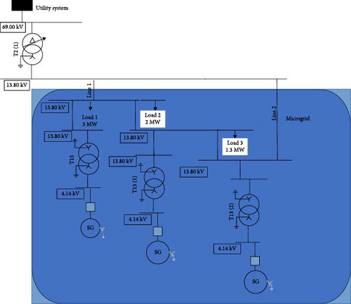
To test the above-mentioned balancing e-IFC, following simulations were conducted using the system model shown in Figure 2:
- 1.
Case Study 1. Frequency of the main grid is reduced to 59.8 Hz (from 60 Hz nominal). The same frequency variation is used to compare the IFC and e-IFC.
- 2.
Case Study 2. In Case study 2, the frequency of the main grid is increased to 60.2 Hz (from 60 Hz nominal). The same frequency variation is used to compare the IFC and e-IFC.
- 3.
Case Study 3. Stepwise grid isolation test is conducted in case 3. The performance of simple IFC and e-IFC is compared.
3.1. Case Study 1: Reduction in Frequency of the Main Grid
- 1.
At t = 5 s, the frequency of the main grid is reduced to 59.8 Hz.
- 2.
At t = 20 s, the frequency of the main grid was brought back to the nominal 60 Hz value.
In this case study, the described test simulates frequency disturbances in the main grid and examines how the e-IFC responds to these events over time.
Two key events occur in the test:
Event 1: Frequency Drop (at t = 5 s)
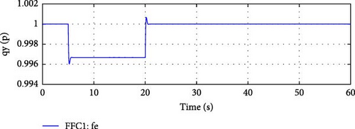
Simulation Setup: At 5 s into the simulation, the frequency of the main grid is reduced from its nominal value of 60 to 59.8 Hz. This represents a situation where the main grid experiences a power deficit or other disturbance, causing a frequency drop below the expected level. Figure 3 demonstrates the induced or simulated change in the grid frequency.
Microgrid Response:
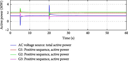
Frequency Response Control Activation: The reduction in grid frequency triggers the microgrid’s frequency response control within the e-IFC. Since the main grid frequency has fallen below the frequency deadband, the e-IFC reacts by initially increasing the active power output from the DDGUs, as shown in Figure 4.
Active Power Flow Control: As the DDGUs increase their power output, the microgrid becomes less reliant on power from the main grid. This results in a reduction in the power flow through the interconnection lines between the microgrid and the main grid.
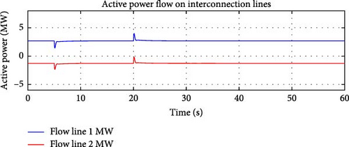
Flow Deadband Monitoring: Once the decrease in power flow from the grid exceeds the flow deadband, the flow control mechanism within e-IFC attempts to decrease the DDGUs’ output to prevent over-adjustment and bring the active power flow closer to the desired reference range, as shown in Figure 5.
Event 2: Frequency Restoration (at t = 20 s) Simulation Setup: At 20 s into the simulation, the main grid’s frequency is restored to the nominal value of 60 Hz. This simulates the recovery of grid stability, where the frequency is returned to normal operating conditions.
Microgrid Response:
Frequency Response Control Deactivation: Once the grid frequency is brought back to 60 Hz, the frequency response controller within the e-IFC no longer detects an abnormal condition. As a result, it reduces the active power output from the DDGUs, which had been increased during the frequency drop.
Active Power Flow Control: As the DDGUs’ output decreases, the microgrid needs more power from the main grid to meet its demand. This leads to an increase in the active power flow through the interconnection lines.
Flow Deadband Monitoring: If the power flow from the grid increases beyond the flow deadband, the flow control will adjust by slightly increasing the DDGUs’ output to reduce grid dependency and ensure that the power flow remains within allowable limits.
Objectives of the Test
Evaluate Frequency Response: The test is designed to assess how effectively the e-IFC’s frequency response control reacts to deviations in the main grid’s frequency. The system should respond promptly to stabilize both the microgrid and the grid’s frequency.
Test Power Flow Control: The test also examines how well the active power flow control manages the power exchanged between the microgrid and the main grid, ensuring that the flow remains within predefined limits (deadbands) to prevent overloading the interconnection lines.
Verify Control System Coordination: The balancing actions of both the frequency response control and the active power flow control are validated in this scenario. These systems must work in tandem to maintain grid stability, adjusting the power output of the DDGUs based on real-time grid conditions.
Power Flow Stability: Monitoring the power flow through the interconnection lines ensures that the flow remains within the allowable deadband, indicating that the microgrid’s controllers are successfully balancing local generation with grid imports.
This test demonstrates the capability of the e-IFC to dynamically adjust its power output in response to grid disturbances, ensuring stability, and maintaining reliable operation through a combination of frequency and active power flow control.
If the same operating conditions are tested for simple IFC, then we get following results:
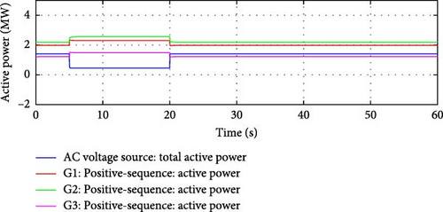
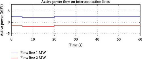
It is evident from Figures 6 and 7, that the simple IFC was not able to maintain the active power flow over the interconnection lines. The frequency controller was able to dominate during the frequency event, while the flow controller was not able to maintain the sum of the active power flow over the interconnection lines while the frequency was depressed.
Performance of the Simple IFC
Inability to maintain Active Power Flow: The simple IFC failed to regulate the sum of the active power flow over the identified interconnection lines between the microgrid and the main grid effectively during the frequency disturbance. This issue arises because simple IFC was not sophisticated enough to handle the dynamic nature of the power flow, especially during events where there is a significant change in grid conditions (such as frequency deviations).
Impact on Interconnection Lines: The active power flow over the interconnection lines fluctuated outside the expected or desired range, meaning that the microgrid’s control system did not effectively balance the power exchange with the main grid.
Frequency Control Dominance During the Event: During the frequency event (when the grid frequency was depressed), the frequency controller took priority in managing the microgrid’s response. The frequency controller is designed to react to deviations from the nominal grid frequency (such as when the frequency drops below 60 Hz), increasing or decreasing the active power output of the DDGUs to stabilize the frequency.
3.2. Case Study 2: Increase in Frequency of the Main Grid
- 1.
At t = 5 s, the frequency of the main grid is increased to 60.2 Hz.
- 2.
At t = 20 s, the frequency of the main grid brought back to the nominal 60 Hz value.
Opposite to Case Study 1, when the frequency of the main grid is increased, the e-IFC was still able to maintain the sum of the active power flow over the two interconnection lines close to the flow reference.
Frequency Increase vs. Frequency Decrease: When the grid frequency increases, it indicates an oversupply of power, leading to the need for the microgrid to reduce its active power generation to help balance the system. Figure 8 shows the simulated change in frequency.

e-IFC Response: The e-IFC, as opposed to the basic version, was designed to respond more effectively to changes in both frequency and active power flow. The controller in this instance was able to maintain the total active power flow over the two interconnection lines around the intended flow reference, even while the main grid’s frequency has increased, demonstrating optimal performance.
e-IFC Functionality
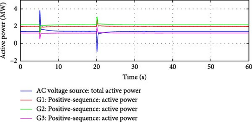
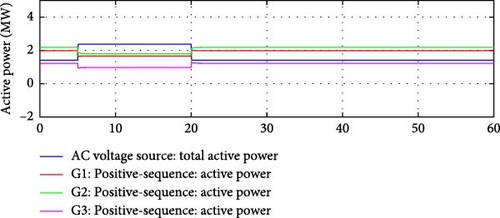
Frequency Response: The e-IFC includes advanced coordination between the frequency controller and the flow controller. When the frequency of the main grid increases, the frequency response controller reduces the output from DDGUs. Figure 9 shows that the active power output from the DDGUs comes back to the initial value after a small transient caused by the change in the system’s frequency. It also demonstrates the active power flow from the main grid remains within the allowable range of the reference (1.4 MW).
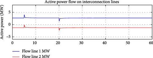
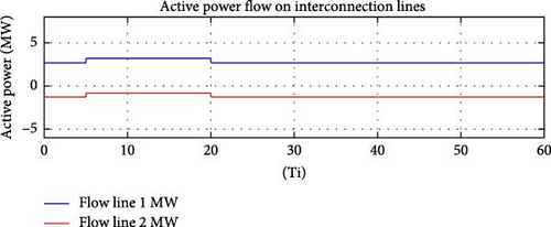
Flow Control Coordination: Simultaneously, the flow controller monitors the active power flow through the interconnection lines. As the DDGU output is reduced, power from the main grid naturally increases to meet the demand of the microgrid. On the other hand, the improved IFC makes sure that the total power flow over the connecting lines remains near the flow reference (i.e., the desired power exchange level). Figure 10 shows the active power flow over the two interconnection lines. It is evident in Figure 10 that the active power flow on the interconnection lines remains closely aligned with the desired power exchange level, demonstrating the effectiveness of the improved IFC controller.
Effective Use of Flow Reference:
Flow Reference Maintenance: The flow reference represents the ideal or optimal amount of active power flow that should pass through the interconnection lines between the microgrid and the main grid. In this case, despite the frequency increase in the main grid, the e-IFC maintained the power flow near this reference point. This was achieved by balancing the DDGUs’ output and the power imported from the grid, ensuring that the sum of active power over both interconnection lines remained within the allowable range.
Flow Deadband Management: The controller effectively managed the flow deadband, the allowable range of deviation from the flow reference. This prevented large fluctuations in power flow, which could have caused instability or stress on the interconnection lines.
Implications for Microgrid Stability
Maintaining Stability During Frequency Increase: The ability of the e-IFC to maintain power flow close to the flow reference, even during a frequency increase, is a crucial improvement. In practical terms, this means that the microgrid can operate more smoothly without causing imbalances in the power exchange with the main grid.
The results of the same simulated steps but with a simple IFC is given below.
Figures 11 and 12 demonstrate that the simple IFC, as expected, again failed to maintain the sum of the active power flow over the interconnection lines during the time when the main grid’s frequency was over the normal value.
3.2.1. Case Study 3: Stepwise Grid Isolation
- 1.
At t = 6 s, Line 1 is tripped.
- 2.
At t = 20 s, Line 2 is tripped. Microgrid operated in grid isolation mode after 20 s.
The stepwise grid isolation test for a microgrid involves simulating a transition from grid-connected operation to grid isolation mode by sequentially tripping interconnection lines between the microgrid and the main grid. This test is critical for evaluating the microgrid’s or active power sharing controller’s resilience and ability to operate independently, ensuring a smooth transition without significant disturbances to local loads. Below is an elaboration of the test with each event and the expected response from the microgrid.
Stepwise Events Simulated
Event 1: Line 1 Trip at t = 6 s.
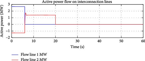
At 6 s into the simulation, Line 1, which is one of the interconnection lines between the microgrid and the main grid, is tripped. This causes the microgrid to lose one of its primary paths for power exchange with the main grid. The overall active power flow is to be maintained at the flow reference level by the e-IFC.
Power Flow Redistribution: With Line 1 tripped, the microgrid can no longer export or import power through this line. As a result, the remaining Line 2 will need to handle the entire power exchange between the microgrid and the main grid.
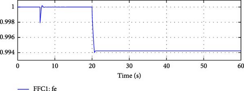
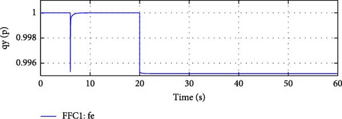
Frequency Stability: During the transition, the microgrid was able to maintain its frequency, as shown in Figure 13.
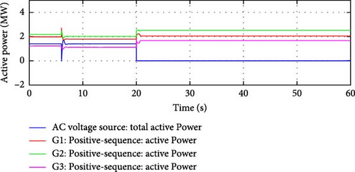
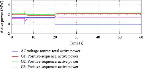
Active powers from the DDGUs, shown in Figure 14, adjust to ensure interconnection flow remains within allowable limits.
Active Power Flow Controller Adjustment: The active power flow controller, e-IFC detected the change in power distribution caused by the loss of Line 1 and adjust the active power flow through Line 2 to ensure ideal operation of the microgrid by maintaining the same overall (sum of active power flows over Line 1 and 2) active power flow (equal to flow reference) over only one interconnection line, Line 2. Figure 15 shows that the e-IFC was able to achieve an active power flow from main grid equal to the sum of initial line flows. The controller worked to maintain the flow close to the flow reference, ensuring the ideal operation of the microgrid under N-1 operating conditions.
Event 2: Line 2 Trip at t = 20 s.
At 20 s into the simulation, Line 2 is also tripped, disconnecting the microgrid entirely from the main grid. After this point, the microgrid operated in islanded mode or grid isolation mode, relying solely on its internal power generation to meet local demand.
Transition to Islanded Mode: The microgrid now enters isolation mode, meaning that it must supply its own power without any external support from the main grid. The DDGUs will become the sole source of power for the microgrid, and their control systems must quickly adapt to the new operating conditions.
Frequency Control in Isolation Mode: In grid isolation mode, the only method to vary the active power output from the DDGUs is by varying the frequency. The frequency controller will closely monitor any deviations from the nominal frequency and adjust the active power output from the DDGUs accordingly. As shown in Figure 13, the frequency of the microgrid was to be reduced to compensate for the loss of 1.4 MW import from the main grid. Since for e-IFC the flow control works in opposite direction, therefore the decrease in frequency is expected to be slightly higher than in the case of simple IFC mode.
The results of the same test conducted with simple IFC mode are given below.
Comparing Figures 13 and 16 confirms that the change in frequency in the case of e-IFC (0.994 pu) is slightly greater than simple IFC (0.995 pu).
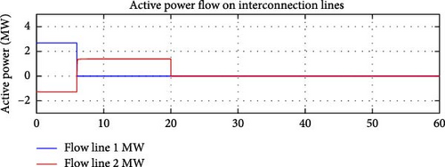
Results shown in Figures 14 and 17, demonstrate that both IFC and e-IFC were able to adjust the DDGU’s active power output, after the loss of first interconnection line, in a manner that the flow of active power at the remaining interconnection line remains within the allowable limits or close to the flow reference. The same is depicted in Figures 15 and 18.
Active Power Redistribution: Since the microgrid can no longer import power from the main grid, the active power output of the DDGUs increased to meet local demand.
The stepwise grid isolation test simulates the gradual transition of a microgrid from grid-connected to islanded operation by tripping one interconnection line at a time. After Line 1 is tripped at t = 6 s, the microgrid experiences a shift in power flow, with Line 2 handling the full exchange with the main grid. When Line 2 is tripped at t = 20 s, the microgrid enters grid isolation mode, relying entirely on its internal generation to meet demand. During this transition, the microgrid maintained stability in terms of active power flow and frequency, requiring coordinated control mechanisms to ensure smooth operation without significant disturbances to local loads.
4. IRFC
For a microgrid with multiple interconnections with the main grid(s), the IRFC is designed to control the flow of the reactive power between the microgrid and the main grid to a particular predefined reference value. Similar to IFC, this controller is also designed to monitor the sum of the reactive power flow on the designated interconnection lines and will work to ensure that the overall flow towards or from the microgrid remains constant. This will ensure that the microgrid acts as a constant load or a generator to the main grid even with reference to the reactive power flow.
Reactive power is critical in maintaining voltage levels, ensuring that both the microgrid and the main grid operate efficiently without voltage instability or fluctuations.
Overview of Reactive Power Flow Control in a Microgrid
Reactive power flow control in a microgrid interconnected with the main grid ensures that voltage stability is maintained across the system. Reactive power flow is influenced by the demand from local loads and the overall voltage profile of the microgrid and the interconnection with the main grid.
When the microgrid operates in grid-connected mode, the IRFC continuously monitors the sum of reactive power flows across all designated (Line 1 and Line 2 in our case) interconnection lines between the microgrid and the main grid. The controller ensures that the reactive power flow stays within a specific reference range to ensure ideal operation of the micro grid.
Similar to active power control (IFC), the IRFC monitors the total reactive power flow over all (or designated) interconnection lines between the microgrid and the main grid. The sum of reactive power flows through the interconnections is calculated and compared to a reference value. This reference value corresponds to the optimal amount of reactive power exchange needed to maintain voltage stability across the microgrid.
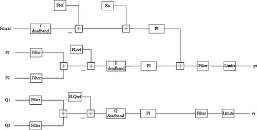
If the sum of reactive power flowing through the interconnection lines deviates from the reference, the IRFC will try to take corrective actions by instructing the local DDGUs to adjust their reactive power output. The overall control block diagram of the e-IFC with integrated IRFC is given in Figure 19.
Reactive Power Compensation by DDGUs:
Each DDGU in the microgrid is capable of producing and absorbing reactive power, allowing it to compensate for any mismatches between reactive power supply and demand.
If the sum of reactive power flow through the interconnections falls outside the acceptable range (beyond the deadband), the DDGUs will adjust their reactive power output to bring the total reactive power flow closer to the reference value.
Proportional-Integral (PI) Control: The reactive power adjustment by the DDGUs is based on the PI controller. Each DDGU has a gain factor (KpQFL and KiQFL) that determines how strongly it reacts to changes in the overall reactive power flow. These gains ensure that the DDGUs respond in proportion to the size of the reactive power imbalance.
Introduction of a Deadband:
To avoid unnecessary and frequent reactive power adjustments for small fluctuations, a deadband is introduced in the controller. The deadband allows the sum of the reactive power flow to vary slightly around the reference value without triggering reactive power corrections.
This deadband reduces the wear and tear on equipment caused by constant adjustments and ensures that the reactive power flow stays within an acceptable range, promoting system stability.
Load Variation and Reactive Power Compensation: When the load within the microgrid varies, there may be an accompanying change in the local demand for reactive power. Increased loads often lead to increased reactive power requirements to maintain voltage stability. In this scenario, the local DDGUs will automatically compensate for these load variations by adjusting their reactive power output. For instance, if the microgrid experiences a high reactive power demand due to inductive loads (e.g., motors), the DDGUs will produce more reactive power to stabilize the voltage.
Response to DDGU Trips:
If one or more DDGUs within the microgrid trip or go offline, the remaining DDGUs will need to adjust their reactive power output to maintain a constant flow of reactive power over the interconnection lines. This ensures that the overall reactive power flow across the interconnections stays balanced and that the system voltage does not drop or rise uncontrollably.
System-Wide Reactive Power Compensation:
One of the key strengths of IRFC is the ability to balance reactive power across multiple interconnections. If one DDGU is unable to meet the reactive power demand due to a fault or trip, the remaining DDGUs will increase their reactive power output to ensure that the sum of reactive power flow remains constant.
In contrast, any reactive power controller designed at the feeder level, like FFC for active power, may lead to isolated pockets of voltage instability if one feeder experiences high reactive power demand that the local DDGU cannot compensate for, as other DDGUs in the system may not respond. By controlling the reactive power flow centrally, the IRFC ensures that the voltage levels across the microgrid are more stable and less prone to fluctuations, even during load variations or system disturbances.
Load Variations and Reactive Power Balancing: The ability of DDGUs to compensate for local load variations in interconnection reactive flow control ensures that the microgrid can maintain stable operation even during periods of high reactive power demand.
In summary, the IRFC (being part of the e-IFC) manages the sum of reactive power flow across designated or all interconnections between the microgrid and the main grid, comparing it to a reference value and making necessary adjustments.
Deadbands help reduce unnecessary reactive power adjustments, ensuring stability without constant corrections.
This comprehensive control system ensures that both active and reactive power flows are effectively managed by a microgrid connected to the main grid, supporting overall system stability and reliability and fulfilling the requirements of an ideal microgrid.
5. Simulation Results and Discussions
- 1.
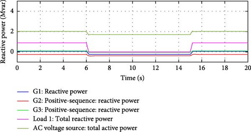
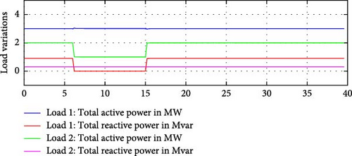
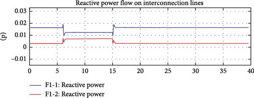
Case Study 4. Reactive power demand variation. Using the same microgrid model, as shown in Figure 2, reactive demand of Load 1 (0.9 MVAr) was ramped down to 0 MVAr at t = 6 s in 0.2 s. The reactive demand was then ramped back to 0.9 MVAr at t = 15 s in 0.2 s.
- 2.
Case Study 5. Active and reactive power demand variation Reactive demand of Load 1 (0.9 MVAr) was ramped down in 0.2 s to 0 MVAr and active power demand of Load 2 is ramped down to 1 MW (from 2 MW in 0.2 s) at t = 6 s. The reactive demand of Load 1 was then ramped back up to 0.9 MVAr and active demand of Load 2 was also restored back to 2 MW at t = 15 s.
- 3.
Case Study 6. Active power, reactive power, and frequency all varied simultaneously. All three parameters (Frequency of the grid, Reactive demand of Load 1, and Active demand of Load 2) varied at t = 6 s.
Load 1:100% reactive power ramped down to 0 MVAr in 0.2 s (from 0.9 MVAr) at t = 6 s, and then ramped back up to the previous value in the same time (0.9 MVAr in 0.2 s) at t = 15 s.
Load 2:50% Active power ramped down to 1 MW at t = 6 s, and then ramped back up to the previous value (2 MW in 0.2 s) at t = 15 s.
The frequency of the grid was dropped instantly to 59.8 Hz at t = 6 s and returned back to normal value (60 Hz) at t = 15 s.
5.1. Case Study 4: Reactive Power Demand Variation
To test the performance of the IRFC section of the e-IFC, the reactive power demand of one of the simulated loads (Load 1) within the microgrid was reduced to 0 MVAr from 0.9 MVAr. This internal variation in the reactive power demand will induce a change in the overall reactive power flow, especially flow from the interconnection lines. Since Load 1 is connected to the bus where one of the interconnection lines (Line 1) is connected, therefore any change in Load 1′s reactive demand should have a direct impact on the sum of reactive power flowing over the interconnection lines.
Impact on Interconnection Reactive Power Flow:
The reduction in Load 1′s reactive power demand caused a decrease in the reactive power flow over Line 1. The sum of reactive power flows across both interconnection lines (Line 1 and Line 2) was also reduced initially, as the overall reactive power demand of the microgrid was decreased.
The e-IFC, specifically the IRFC section, detected this change and worked to maintain reactive power flow by adjusting the output of the local DDGUs.
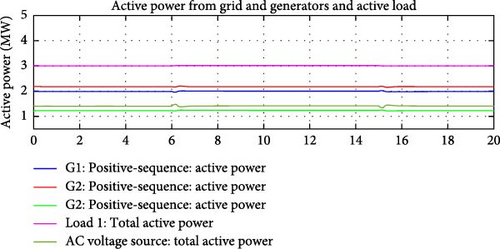
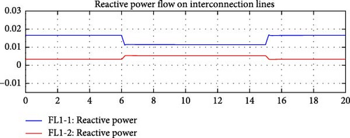
Results (Figures 20–22) demonstrate the performance of the e-IFC with IRFC, as it was able to maintain a constant reactive power flow over the interconnection lines, Line 1 and Line 2. The internal reactive demand variation was compensated by the DDGUs by varying their reactive power outputs.
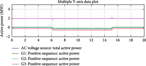

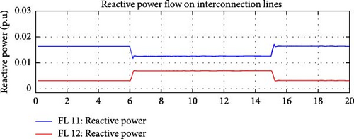
Only one load (Load 1) was selected to simulate the reactive demand variation; however, all three DDGUs contributed to compensate for the internal variation.
Reactive Power Flow Stabilization:
The e-IFC, with the integrated IRFC, was able to maintain a steady and controlled reactive power flow across both Line 1 and Line 2, which connect the microgrid to the main grid.
This is a critical achievement, as reactive power flow management directly impacts voltage stability in the microgrid. Any significant variations in reactive power can cause voltage fluctuations, leading to potential instability.
Despite the simulated reduction in reactive power demand from Load 1 (from 0.9 to 0 MVAr), the system responded quickly to stabilize the reactive power flow and avoid any potential voltage instability across the microgrid and its interconnections with the main grid.
Compensation by DDGUs:
A noteworthy aspect of the test is the cooperative behavior of the DDGUs. While only Load 1 was selected to undergo a change in reactive power demand, all three DDGUs contributed to compensating for this internal variation.
The e-IFC, through its PI control, ensured that each DDGU adjusted its reactive power output in proportion to the deviation in the overall reactive power flow.
This demonstrates the collective responsibility of the DDGUs in maintaining system stability, as the e-IFC coordinates the reactive power contributions from each DDGU to ensure that the overall reactive power flow remains constant.
Load 1′s Impact and System Response:
Load 1, which was chosen for the reactive power demand variation, has a direct impact on Line 1, as it is connected to the bus where Line 1 is located. The reduction in Load 1′s reactive power demand caused an initial disturbance in the reactive power flow through Line 1, which was quickly detected by the IRFC. The IRFC immediately responded by adjusting the reactive power outputs of the DDGUs, ensuring that the total reactive power flow over Line 1 (and by extension, Line 2) stayed within the desired range, close to the reference values.
This outcome highlights the robustness of the IRFC in managing the reactive power flow over the interconnection lines, as IFC demonstrated that active power flow. The ability of the IRFC to respond quickly to changes in reactive power demand enhances the overall resilience of the microgrid, ensuring stable operation even during dynamic load variations.
5.1.1. Case Study 4A: Reactive Power Demand Variation With Simplified Excitation System (SEXS) Automatic Voltage Regulator (AVR) at DDGUs
To highlight and benchmark the performance of IRFC, the same reactive power variation test is conducted while using a simple and standard SEXS model of AVR at DDGUs. Its main function is to regulate the output voltage of a synchronous generator by controlling the excitation current supplied to the generator’s field windings. The SEXS model is part of the IEEE standard models for excitation systems and is used extensively in power system studies due to its simplicity and ability to represent basic dynamic behaviors of excitation systems. The SEXS model uses a transfer function to represent the voltage regulator’s dynamics and the generator’s response. In simplified terms, the SEXS model can be represented by a block diagram (Figure 23) that includes:

- •
A voltage error signal (difference between reference voltage and actual terminal voltage),
- •
An amplifier with a gain,
- •
A time delay representing the response of the exciter,
- •
Saturation limits to prevent over-excitation or under-excitation.
IFC was used as the active power controller during this test.
Results depicted in Figures 24–27 clearly demonstrate that SEXS exciter was not able to control the flow on the interconnection lines, as expected.
5.2. Case Study 5: Active and Reactive Power Demand Variation
Again, for Configuration 2, as shown in Figure 28, reactive demand of Load 1 (0.9 MVAr) was ramped down in 0.2 s to 0 MVAr and active power demand of Load 2 is ramped down to 1 MW (from 2 MW in 0.2 s) at t = 6 s. The reactive demand of Load 1 was then ramped back up to 0.9 MVAr and active demand of Load 2 was also restored back to 2 MW at t = 15 s.

This test was designed to test both sections (active and reactive power flow control) of the e-IFC. By ramping down active and reactive power at the same instant will evaluate the robustness of the controller as both active and reactive power flows will have to be maintained at desired and corresponding reference levels.
By simultaneously manipulating both active and reactive power levels, the test evaluates the ability of the e-IFC to coordinate the two types of power flows, which are inherently interrelated but controlled separately. This will provide insights into how well the IRFC and Active Power Flow Control sections of the e-IFC perform together.
The test will assess whether the e-IFC can maintain both active and reactive power flows within the acceptable deadbands, ensuring that any deviation caused by the ramp-down is corrected quickly without oscillations or overcorrections.
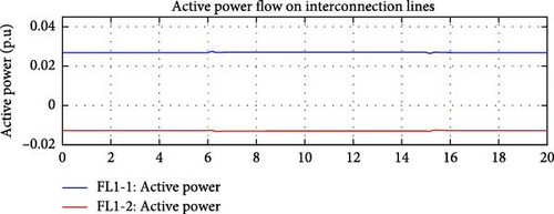
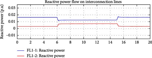
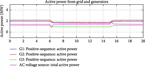
Figure 28 shows the simulated active and reactive load variations. Figures 29–32 demonstrate the action of the active and reactive power flow control simultaneously. Balanced active power flow control and IRFC worked together to ensure sum of both active and reactive power flows over the interconnection lines remains close to the corresponding flow reference values. DDGUs were able to compensate active and reactive power variances diligently. Reactive and active power flows on the interconnection lines are captured in Figures 29 and 30, respectively.
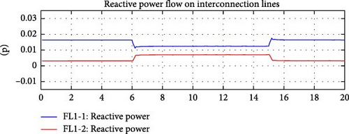
These results provide a detailed visualization of how the e-IFC, incorporating both active power flow control and the IRFC, operates when simultaneously managing active and reactive power flows. The balanced control strategy ensures that changes in either active or reactive power demand are compensated quickly and efficiently by the DDGUs within the microgrid. Maintaining both power flows close to their respective reference values is essential to prevent instability in the system, such as frequency deviations (linked to active power) and voltage fluctuations (linked to reactive power).
A key feature demonstrated in these results is the coordination and independence between the active power flow control and IRFC.
This balanced coordination ensures:
Simultaneous compensation: Both active and reactive power flows are maintained in a stable range, despite simultaneous changes in demand for both. This shows that the e-IFC can handle complex dynamic situations where both types of power flows are affected.
Dynamic response from DDGUs: The DDGUs dynamically adjust their power outputs based on the detected deviations from reference values. The active power flow control adjusts the DDGUs’ active power output, while the IRFC coordinates the DDGUs’ reactive power output. This dual control ensures that the total power flows over the interconnection lines remain within the desired ranges.
Stable operation across interconnection lines: By maintaining both power flows close to their reference values, the e-IFC prevents disturbances from propagating across the microgrid. If active or reactive power flows deviate significantly from the references, it could lead to frequency or voltage instabilities, negatively impacting the microgrid’s interaction with the main grid. The figures show how the e-IFC keeps both flows within acceptable limits.
The figures highlight how the DDGUs smoothly transition to compensate for changes in power demand, whether active or reactive. This compensation is crucial to maintain balanced power flow over the interconnections, ensuring that neither active nor reactive power flows deviate significantly from the reference values.
5.2.1. Case Study 6: Frequency, Active, and Reactive Power Demand Variation
This test intends to test all three features (balancing active power control, frequency response control, and IRFC) of e-IFC at the same time. All three parameters are varied at the same instant to evaluate the stability and ability of the e-IFC.
Simultaneous Control of Multiple Parameters:
By varying active power, frequency, and reactive power at the same time, the test challenges the e-IFC’s ability to handle multivariable control. The three control mechanisms must work in tandem to prevent disturbances in one parameter from affecting the others.
All three parameters (frequency of the grid, reactive demand of Load 1 and active demand of Load 2) varied at t = 6 s. Load 1 − 100% reactive power ramped down to 0 MVAr in 0.2 s (from 0.9 MVAr) at t = 6 s, and then ramped back up to previous value in the same time (0.9 MVAr in 0.2 s) at t = 15 s. Load 2 − 50% Active power ramped down to 1 MW at t = 6 s, and then ramped back up to previous value (2 MW in 0.2 sec) at t = 15 s. The frequency of the grid was dropped instantly to 59.8 Hz at t = 6 s and returned back to normal value (60 Hz) at t = 15 s.
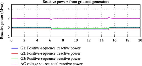
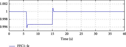
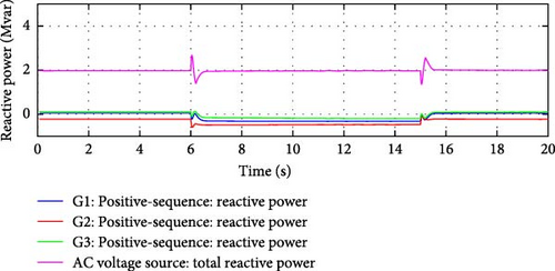
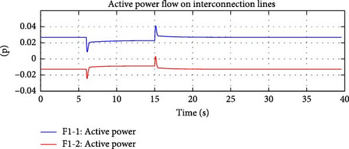
Figure 33 shows the simulated change in the system frequency. Figure 34 captures the active and reactive power variations simulated for Load 1 and Load 2. Figures 35–38 demonstrate that the e-IFC was able to respond successfully for all three simulated variations. It was able to independently control and manage active and reactive power flows on the two interconnection lines to ensure microgrid’s ideal operation even during dynamic operating conditions.
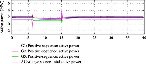
The key point in this test was both sections of the e-IFC related to balancing active power were tested at the same time, as the active demand of the microgrid was varied along with the frequency. The controller was able to only compensate the varied active demand and was able to balance the impact of the frequency response. The balancing active power control mechanism worked in tandem with the frequency response control, ensuring that the microgrid’s internal active demand was met, while also addressing the frequency deviations from the main grid. This demonstrates the robustness and coordination between the different sections of the e-IFC, especially under dynamic operating conditions.
To demonstrate the independence of the active and reactive power controllers (IRFC) within e-IFC, the controller was tested by also varying the microgrid’s internal reactive demand at the same instant. Figure 36 clearly demonstrates that the reactive power from the grid remained at a constant value during these variations. Although, reactive power flow on two interconnection lines did vary, as shown in Figure 38. However, the sum of the reactive power flow remained close to the flow reference value.
This test focused on the ability of the e-IFC to independently control active and reactive power flows on the two interconnection lines. Results demonstrate that the active and reactive power flow on both interconnection lines was effectively managed. The e-IFC was able to detect the changes in the active power demand and respond accordingly by adjusting the DDGUs’ active and reactive power outputs.
The results collectively highlight the robustness and flexibility of the e-IFC in controlling both active and reactive power flows, even under complex and dynamic conditions.
5.3. Independent Active and Reactive Power Control
In modern power systems, particularly in microgrids with distributed generation and high renewable penetration, the ability to independently control active (real) and reactive power is essential for ensuring system stability, power quality, and efficient/ideal operation. While active power (measured in watts) is directly responsible for doing useful work (running electrical devices, lighting, etc.), reactive power (measured in volt-amperes reactive, or VARs) is essential for maintaining voltage levels across the power grid, which is necessary for the transmission of active power.
- •
If the system were to experience a change in reactive power demand (e.g., from inductive loads), and the active power control was not decoupled, this could result in frequency deviations or power imbalances.
- •
Conversely, variations in active power due to load changes or generation output fluctuations could induce undesirable voltage variations if reactive power is not independently controlled.
The decoupling of active and reactive power control ensures that disturbances or adjustments in one do not propagate or negatively affect the other. Independent control mechanisms provide the ability to manage these types of variations locally and effectively.
- •
Renewable generation introduces variability: Renewable energy sources, especially solar and wind, exhibit intermittency in power output. Independent active power control allows the system to manage variations in active power output from these sources without compromising the voltage stability provided by reactive power control.
- •
Power electronics in DG units: Many DG sources, like solar inverters, rely on power electronics that allow independent control of active and reactive power. This is critical for voltage regulation in the distribution network while also ensuring that the microgrid can maintain frequency stability.
The ability to manage active and reactive power independently is therefore critical to the successful operation of microgrids and renewable energy systems, where dynamic changes in power generation and consumption can have rapid and significant effects on both voltage and frequency. In systems where microgrids are interconnected with a larger grid, it is essential to independently control the flow of active and reactive power to maintain stability and avoid causing disturbances in the main grid.
In all the simulated tests presented above, the e-IFC successfully demonstrated its capability to independently control both active and reactive power flows over the interconnection lines. This achievement highlights the robustness of the controller’s design and its ability to manage power dynamics in real-time. With the enhancements made to the IFC, transforming it from a simple active power controller into a comprehensive PQ controller (active-reactive power controller), the independent management of active and reactive power is a key and critical feature.
6. Conclusion
The e-IFC design presented in this paper significantly improves the stability and efficiency of microgrid operations, particularly in managing both active and reactive power flows. Through the addition of frequency response balancing control and the IRFC, the system is better equipped to handle grid disturbances and ensure smooth transitions between grid-connected and islanded modes. Simulation results demonstrate that the e-IFC outperforms the standard IFC, particularly in scenarios involving frequency deviations and power flow imbalances. By providing independent control of active and reactive power, the enhanced design ensures more stable and reliable microgrid operation, making it an essential upgrade for future smart grid applications.
Future studies might expand the suggested improved IFC to support real-time implementation and assess its resilience to real-world hardware limitations and communication delays utilizing hardware-in-the-loop (HIL) testing platforms. To further improve dynamic performance, automatic tweaking of the controller gains (Kp, Ki) via adaptive or metaheuristic optimization techniques will be investigated. The performance of the controller in large-scale microgrids with more than two connections, including situations with simultaneous multi-line failures, will be examined in further research. The integration of sensitivity analysis of flow deadband thresholds will enhance system resilience while reducing superfluous control operations.
Disclosure
The manuscript focuses on enhancing the interconnection flow controller (IFC) by integrating frequency response balancing and an interconnection reactive power flow controller (IRFC) to optimize active and reactive power sharing in microgrids with multiple grid interconnections. It presents key design improvements, mathematical formulations, and simulation results, demonstrating the superiority of the enhanced controller (e-IFC) over standard methods. In contrast, the thesis provides a broader analysis, including comparative studies, literature reviews, and extended simulations to validate the controller across various operational conditions. The manuscript serves as a core technical contribution within the thesis entitled, “Active and Reactive Power-Sharing Method for Micro Grids With Multiple Grid Connections” highlighting specific innovations, while the thesis expands on practical applications, stability analysis, and real-world adaptability.
Conflicts of Interest
The authors declare no conflicts of interest.
Author Contributions
Syed Muhammad Rizvi: conceptualization, software, formal analysis, data curation, writing – original draft. Ahmed Abu-Siada: supervision, methodology, administration. Md. Fatin Ishraque: writing – review and editing, validation, software, investigation. Sk. A. Shezan: Software, supervision, methodology, administration. Innocent Kamwa: supervision, methodology, administration. Ali H. Alenezi: supervision, methodology. Md. Nimul Hasan: writing – original draft, review and editing, validation, software.
Funding
This work was supported in part by the Canada National Sciences and Engineering Research Council through the Laval University, Grant ALLRP567550-21. The authors extend their appreciation to the Deanship of Scientific Research at Northern Border University, Arar, KSA for funding this research work through the project number “NBU-FPEJ-2025-3623-01.”
Acknowledgments
The authors extend their appreciation to the Deanship of Scientific Research at Northern Border University, Arar, KSA for funding this research work through the project number “NBU-FPEJ-2025-3623-01.”
Open Research
Data Availability Statement
The data supporting this study’s findings are available from the corresponding author upon reasonable request.


