Metal-Organic Frameworks Coated Cellulose Nanofibers for Localized Carbon Dioxide Capture
Abstract
The consequences of global warming due to increasing levels of greenhouse gas emissions stress the need to develop carbon capture technologies expeditiously. Metal-organic frameworks (MOFs) have been proven to be effective carbon dioxide (CO2) sorbents, but challenges lie in their integration into practical applications owing to the hurdles in processing the powder MOFs into usable structures. Herein, the Cu-MOFs nanocrystals were in situ grown over different cellulose substrates, including bacterial cellulose nanofibers lamellas (BCNFLs) and wood-derived cellulose nanofibers (WCNFs). The successfully prepared sorbents were evaluated for CO2 capture applications, along with their kinetic and diffusion dynamics. The loading of MOFs nanoparticles was confirmed via FESEM, showing the interconnected network of cellulose nanofibers (CNFs) and interwoven MOFs particles. The surface area and porosity of the samples, analyzed by the N2 sorption method, were proportional to the MOFs in the sorbents. The MOFs/BCNFLs and MOFs/WCNFs composites demonstrated CO2 uptake of approximately 1 and 1.19 mmol/g, respectively, and maintained stability over numerous cycles, highlighting the robustness of the developed structures. The CO2 sorption isotherms were explained by the Langmuir–Freundlich model, accounting for surface heterogeneity, and exhibited a selectivity () of 49 with a heat of adsorption of 27 kJ/mol. The MOFs/BCNFLs exhibited 2.2 times higher sorption kinetics and a 25% greater diffusion coefficient than WCNFs, attributed to the thin MOFs layer that minimized mass transport limitations. Our findings underscore the significance of structural optimization and the potential of cellulose nanofiber-coated MOFs for practical carbon capture applications.
1. Introduction
Uncontrolled emissions of greenhouse gases, particularly carbon dioxide (CO2) from the energy sector, are exacerbating global warming [1]. CO2 emissions are primarily driven by burning fossil fuels, and given the current reliance on these energy sources, achieving the necessary reductions in carbon emissions remains a significant challenge [2, 3]. One potential pathway for progress includes implementing carbon capture technologies, such as adsorption, absorption, membrane separation, chemical looping, cryogenic distillation, and direct air capture, which can reduce the emission of CO2 into the atmosphere [4, 5]. An alternative way to mitigate global warming is to reduce atmospheric CO2 levels by implementing localized CO2 capture filter systems before they are released. These filters can be made of CO2 capture sorbents such as zeolites, activated carbon, and metal-organic frameworks (MOFs), all of which exhibit considerable sorption capacity [5, 6]. Zeolites are commercially used for CO2 capture applications owing to their good sorption capacity, regenerability, and cost-effectiveness [5]. Meanwhile, MOFs represents a relatively new class of materials with exceptional structural characteristics, including an ultra-high surface area and tunable pore chemistry [7, 8]. They perform better than traditional CO2 sorbents regarding sorption capacity and selectivity [9, 10]. Their versatile chemistry allows for tailored property modifications to suit specific applications. For example, CO2 capture performance can be significantly enhanced by grafting amine functional groups into the MOFs framework [11–13].
Although MOFs are promising materials for CO2 capture, bulk MOFs powder is not ideal for commercial applications due to high pressure drops, particle aggregation, and restricted gas accessibility in fixed bed systems [14]. Typically, these materials are required in the form of specific structured geometries, such as pellets, granules, or monoliths [14]. The geometry of the sorbent structure plays a crucial role in determining sorption kinetics and CO2 capacity [15], while pressure drop associated with sorbent loading and bed design remains a critical factor for real-world applications [15–17]. Depositing the MOFs over facile and flexible polymer composite lamellas can overcome the mass transfer limitations and offer better sorption kinetics. Specifically, cellulose nanofibers (CNFs) are biobased materials that can be produced from agricultural waste or wood biomass. As mentioned above, localized CO2 capture applications need materials that can be transformed into thin film-like structures and coated with MOFs or other carbon capture materials. The CNF offers both the features of being flexible to be processed into various structures and is easily coated with MOFs material owing to surface chemistry [14, 18]. CNFs provide ample surface for MOFs growth and can be employed in CO2 capture applications under mild process conditions [19]. CNFs can be obtained from wood by chemical treatment, often under harsh conditions, and are called wood-derived CNFs [20]. Meanwhile, CNFs can be obtained from microbial fermentation processes called bacterial CNFs [21]. The literature suggests that bacterial cellulose offers advantages over wood-derived cellulose, including high purity, superior mechanical strength, and enhanced sustainability due to its environmentally friendly production process [22]. However, bacterial cellulose has certain limitations associated with low yield, higher cost, and limited scalability due to controlled fermentation processes. In contrast, wood-derived cellulose is economical, readily available, and scalable but may contain impurities from precursors even after purification [23]. Further, bacterial cellulose exhibits greater hydrophilicity than wood-derived cellulose, thereby offering better characteristics as a substrate for coating MOFs nanoparticles [24].
MOFs coating onto a substrate typically involves an organic ligand and a metal precursor serving as a seed [25]. Depending on the desired application and material availability, various techniques can be employed to achieve MOFs deposition, such as atomic layer deposition (ALD), dip-coating, and solvothermal techniques. In ALD-based MOFs synthesis, a thin metal oxide seed layer is first deposited over the substrate and then converted into a MOFs/CNFs composite. This technique typically requires several coating cycles to load a sufficient quantity of MOFs nanoparticles onto the substrate. Commonly reported substrates for MOFs coating via ALD are CNFs, SiO2 nanofibers, etc., which are used in applications such as sensing, catalysis, and gas separation [26, 27]. Bechelany et al. [28] reported the growth of MOFs crystals over electrospun nanofibers using the ALD method. The metal precursor was first deposited over fibers, around 0.2 nm per coating cycle, through several cycles and subjected to solvothermal treatment in a solution containing 2-methylimidazole to form the ZIF-8/nanofibers, yielding uniformly deposited MOFs crystals over nanofibers. However, the ALD method is limited by high costs, stemming from the specialized equipment required, elevated operational expenses, and its limitations for scaling up to larger applications. In addition, the dip-coating strategy has also been reported to deposit MOFs layers over a substrate, wherein the substrate is alternately immersed in a metal solution and a linker solution through multiple cycles to achieve a sufficient MOFs coating [24]. Nonetheless, this technique results in weaker adhesion of the MOFs nanoparticles to the substrate and struggles with complexities in substrate geometry. Furthermore, the solvothermal strategy has been successfully employed for MOFs deposition on substrates [29–31]. The solvothermal method stands out for its versatility (requires simple equipment, enabling the effective coating of a broad range of nanoparticles onto various substrates. For example, Zhao et al. [32] reported MOFs deposition over nanofiber kebabs through the solvothermal method. The MOFs solution was first prepared (UiO-66, 67, and UiO-66-NH2), and kebab nanofibers were added to the MOFs suspension. However, to facilitate heterogenous nucleation and enhance MOFs activity, the nanofibers first required a TiO2 coating using ALD [32]. Therefore, the solvothermal method was employed in this study to deposit the MOFs over the CNFs.
This study investigates Cu-MOFs deposition on two distinct cellulose-based substrates: bacterial cellulose nanofibers lamellas (BCNFLs) and wood-derived cellulose nanofibers (WCNFs). The solvothermal method was used to deposit the Cu-MOFs nanocrystals on these substrates, resulting in the successful development of MOFs/BCNFLs and MOFs/WCNFs composites. The prepared composites were thoroughly characterized to assess their structural, morphological, and surface properties and were further evaluated for CO2 capture applications. Additionally, the impact of substrates on MOFs performance and CO2 sorption kinetics was systematically examined.
2. Materials and Methods
2.1. Chemicals
The following chemicals were used during the synthesis: 1,4-diazabicyclo [2.2.2]octane (DABCO, > 99%, Sigma Aldrich), copper (II) nitrate hemi pentahydrate (> 99.99%, Sigma Aldrich), 9,10-anthracenedicarboxylic acid (H2ADC, 95% Sigma Aldrich), N, N-dimethylformamide (> 99%, Sigma Aldrich), ethanol absolute (VWR) and methanol (> 99.8%, VWR). Microfibrillated cellulose (WCNFs) with 9.6% dry content was provided by MoRe Research AB.
2.2. Synthesis of Bacterial CNFs
The bacterial strain Komagataeibacter sucrofermentans (DSM 15,973) used in this study for cellulose production was purchased from DSMZ (the German Collection of Microorganisms and Cell Cultures). The strain was maintained as cryostocks in 15% (v/v) glycerol and stored at 80 °C. For inoculum preparation, HS (Hestrin–Schramm) medium at pH 6.8 was used [33], containing (g/L) glucose 20; peptone 5; yeast extract 5; citric acid 1.15; and disodium hydrogen phosphate 2.7. A 50 mL culture was incubated statically at 30°C for 72 h. This statically grown culture was then vigorously agitated to separate the bacterial cells from the CNFs, and the resulting cell suspension was used as a bacterial inoculum for BCNFLs production.
To produce bacterial CNFs by K. sucrofermentas, a 500 mL flask containing 200 mL of medium with a carbon source (20 g/L) was inoculated with 10% (v/v) bacterial suspension and incubated statically at 28°C for 16 days. At the end of the cultivation period, the synthesized CNFs membrane was harvested from the culture medium. The CNFs were then alkali-treated with 1 M NaOH by boiling for 1 h to remove the adhered bacterial cells, followed by neutralization in boiling water for 2 h. This process was repeated several times until the BCNFLs became colorless. Finally, the wet BCNFLs was lyophilized for 24 h to remove water, and the dry weight was determined gravimetrically as g/L (dry weight [g] of BNC/volume [L] of production medium).
2.3. Synthesis of MOFs-Coated CNFs
The 200 mg BCNFLs were first soaked in 50 mL of DMF, followed by the addition of 0.6 mmol 9,10-anthracenedicarboxylic acid and 0.5 mmol DABCO. The mixture was stirred for 2 h at 80°C. The 0.6 mmol of copper precursor was separately dissolved into 25 mL of DMF and then added dropwise into the above mixture, forming MOFs-coated BCNFLs. The resulting suspension was stirred for an additional 30 min before being transferred to a Teflon-lined autoclave, which was placed in an oven at 120°C for 48 h to ensure the complete formation and growth of MOFs nanocrystals. After synthesis, the product was centrifuged and repeatedly washed with DMF to remove unreacted material. The purified material was then subjected to solvent exchange with ethanol by soaking for 12 h, followed by washing with ethanol. Finally, the product was washed once with methanol and dried before vacuum thermal activation.
To prepare the MOF/WCNFs composite, the wet WCNFs (9.8% dry contents) was dispersed in 50 mL of DMF and stirred at 80°C until complete evaporation of residual water. The rest of the synthesis procedure was carried out as mentioned above.
2.4. Characterizations
The morphology and structure of the synthesized sorbents were analyzed using scanning electron microscopy (SEM; FEI Magellan 400 field emission XHR-SEM, and JEOL JCM-6000Plus). The crystallinity of the sorbents was analyzed using the AERIS powder X-ray diffractometer (Malvern PANalytical, UK). The thermal stability was evaluated using the STA 449 F3 (Netzsch, Germany). The surface and textural characteristics were measured using the Gemini VII 2390 Surface Area Analyzer (Micromeritics, Norcross, USA). All the gas sorption isotherms measurements were carried out on the abovementioned equipment, Gemini VII. Before gas sorption measurements, the samples were activated at 120°C under vacuum. CO2 sorption kinetic measurements were performed using a thermogravimetric analyzer equipped with differential scanning calorimetry (TGA/DSC, SDT 650, TA Instruments, USA). Before kinetics measurements, samples were pretreated at 120°C for an hour to remove the moisture or gaseous impurities.
3. Results and Discussion
3.1. Production of BCNFLs
Cultivating K. sucrofermentas in HS medium supplemented with 20 g/L glucose resulted in a total BCNFLs production of 2.17 ± 0.14 g/L (Figure 1). This yield is comparable to that of other strains, such as Komagataeibacter xylinus DSM 2004 and DSM 46604, which produced 2.10 and 0.53 g/L of bacterial CNFs, respectively, under similar glucose supplementation conditions [34]. It was observed that various cultivation parameters, including the carbon source, pH, aeration, nitrogen source, and agitation, strongly influence BCNFLs production [35]. For example, different carbon sources affect yield and structural quality, while pH impacts bacterial metabolism. Aeration is crucial for oxygen transfer, and nitrogen sources support cell growth. Among these, agitation has shown the most significant influence, as it directly affects oxygen availability and shear forces, thereby impacting both the yield and quality of BCNFLs [35].

3.2. MOFs Coating on Cellulose Nanofiber Substrates: Structural and Thermal Analysis
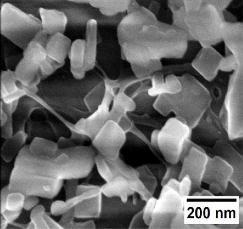
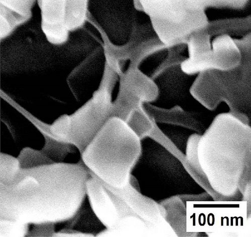
In situ, the coating of MOFs nanoparticles onto different cellulose nanofiber substrates was successfully obtained and analyzed by SEM. The loading of organic linkers on the substrates created a strong attraction with the substrate, while the addition of copper precursors promoted MOFs nanocrystal growth. As shown in Figure 2a,b, MOFs nanocrystals are distinctly grafted onto the surface of BCNFLs, forming a uniform coating. The magnified image (Figure 2b) further reveals the network of nanofibers in the BCNFLs beneath the MOFs layer, confirming the attachment of MOFs particles. In addition, the aspect ratio estimated from the SEM images of pristine BCNFLs was in the range of approximately 130–220.
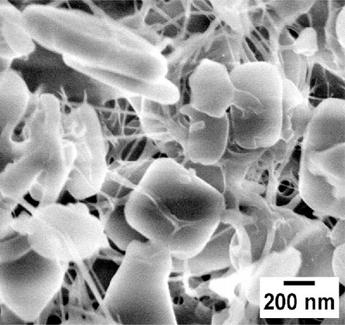
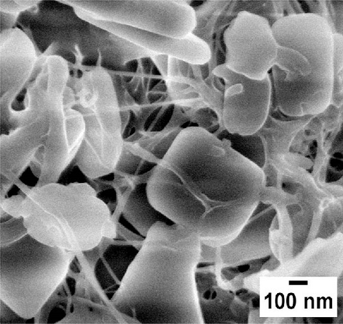
Similarly, Figure 2c,d illustrates MOFs particles grafted onto the nanofibers of WCNFs. Unlike BCNFLs, MOFs particles in WCNFs are distributed around the fiber surface, possibly due to the dispersion difference between lamellas and fibers. The varying size of MOFs nanocrystals is noticeable in the magnified micrographs, suggesting that the growth of MOFs crystals was influenced by the characteristics of substrates, possibly the surface energy and roughness [30]. The observation highlights the crucial role of the substrate in modulating crystal growth. The shape or morphology of MOFs nanoparticles is the same for both composites, which shows that the structure of the substrate did not affect the intrinsic morphology of the MOFs, thereby allowing the MOFs crystals to grow successfully.
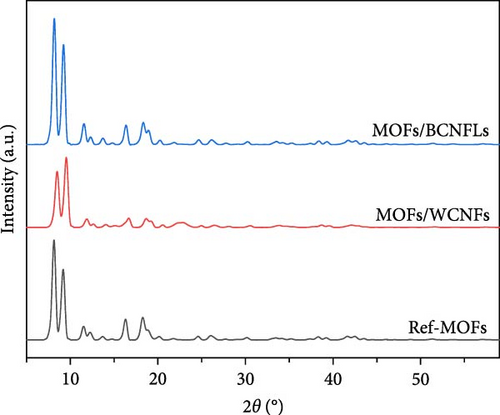
XRD analysis (Figure 3a) confirms the formation of MOFs on both substrates, with characteristic peaks around 8.5° and 9.5° matching reference Cu-MOFs [36, 37]. The MOFs/BCNFLs exhibited sharper peaks, while MOFs/WCNFs showed slight peak broadening and peak shifts, which could be ascribed to the difference in substrate properties and subsequent size of MOFs particles, which was also observed in the SEM micrographs. The absence of CNF peaks suggests low crystallinity and a shielding effect from the intense MOFs diffraction signals [24].
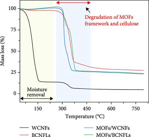
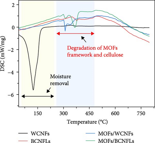
The thermal properties of composites are fundamental in deciding sorption and desorption process parameters. Figure 3b shows the weight loss of the substrate and composites. The WCNFs substrate showed significant weight loss at temperatures below 150°C due to its high moisture content, as mentioned in the methodology section. Another TGA event, showing the weight loss starting at approximately 300°C, could indicate structural degradation of cellulose and the onset of pyrolysis of cellulose [38]. In contrast, the BCNFLs showed negligible moisture-related weight loss, with primary degradation occurring at around 300°C (due to the depolymerization and decomposition of glycosyl units) [39]. The MOFs composites showed a two-step weight loss in the region under 250°C, attributed to moisture and pore-entrapped solvent molecules removal [40]. Their TGA curves show the onset of pyrolysis at around 300°C, with two shoulders corresponding to the collapsing of the MOFs framework and cellulose decomposition, highlighting the thermal stability limitation of MOFs [41, 42]. As shown in Figure 3c, the DSC results complemented the TGA events, showing the endothermic events for moisture removal and the pyrolysis of MOFs and cellulose. Moderate thermal stability up to the temperature of 300°C shows the potential of these composites for various carbon capture applications.
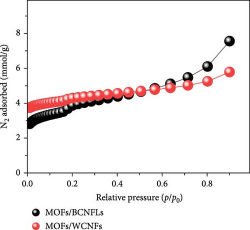
The prepared composites were further characterized by N2 sorption analysis to evaluate their textural properties (Figure 3d). The sorption isotherms show inflection points at a relative pressure of ≤ 0.2, indicative of micro- and mesopores. The isotherm shapes closely reflect Type I and Type IV behaviors, corresponding to low and high pressure regions, respectively. This indicated that the composites comprise a mix of micro and mesopores, reflecting the hierarchical MOFs structure [36]. Landström et al. [36] reported a similar sorption pattern of hierarchical Cu-MOFs, highlighting the importance of porous structure for CO2 capture applications. The surface area of MOFs/WCNFs (363 m2/g) was higher than that of MOFs/BCNFLs (293 m2/g), which could relate to the loading of MOFs on cellulose substrate. The substrate in the form of nanofibers allows a higher degree of nanoparticle coating due to the availability of more surface for MOFs nucleation. Meanwhile, in the case of the BCNFLs, the surface coating is made over the sides of the lamellas. The N2 sorption pattern of both composites closely resembles the pure MOFs sorption isotherms reported by Landström et al. [36], which shows that the MOFs particles determined the textural properties of the composites.
3.3. CO2 Sorption
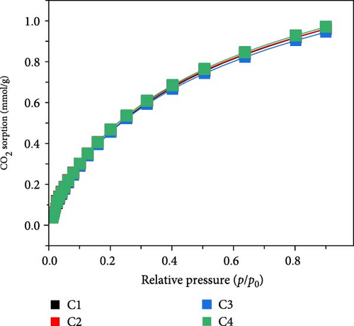
The prepared composites were systematically evaluated for their CO2 capture performance. Figure 4a shows the CO2 sorption isotherms at 20°C for MOFs/BCNFLs, revealing a sorption capacity of approximately 1 mmol/g CO2 at 1 bar. This value aligns closely with the Cu-MOFs loading proportion, considering that the reported CO2 uptake of pure Cu-MOFs is 2.58 mmol/g at 20°C and 1 bar [36]. This shows that CO2 sorption originated from the MOFs and that BCNFLs did not significantly contribute to the sorption; rather, it acted as a template for the dispersion of MOFs. The MOFs/BCNFLs was further evaluated for cyclic CO2 sorption to assess the stability of the composite for practical applications. The sorbent demonstrated consistent CO2 uptake over four consecutive cycles, with no noticeable performance degradation, confirming the framework’s robustness [43] and regenerability. This suggests that CO2 capture occurs mainly via physisorption, which ensures the complete regeneration of the sorbent under vacuum without thermal treatment.
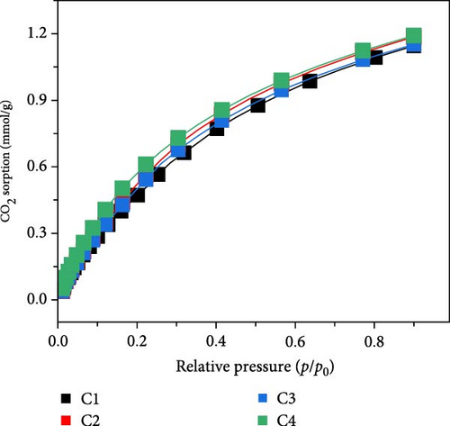
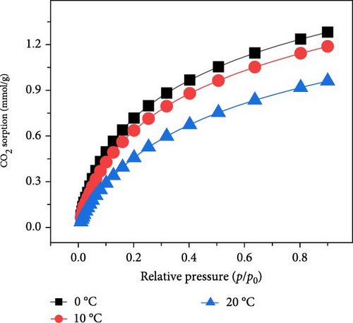

Similarly, the CO2 sorption of MOFs/WCNFs was evaluated, and the results are shown in Figure 4b. The sorbent exhibited a CO2 uptake of 1.19 mmol/g, showing superior performance compared to MOFs/BCNFLs. The enhanced sorption capacity of the sorbent can be attributed to a higher MOFs loading on the cellulose nanofiber. Cyclic CO2 sorption tests further validated the composite’s stability and reusability, with MOFs/WCNFs maintaining consistent performance for four consecutive cycles. The physisorption mechanism in Cu-MOFs can proceed either via van der Waal forces or electrostatic interactions between CO2 and active adsorption sites [44, 45]. As confirmed by N2 sorption isotherms, the microporous characteristics exhibited by both composites could play a dominant role as trapping sites for CO2 molecules. Additionally, N2 sorption isotherms demonstrated a hierarchical structure for both the composites, exhibiting extra structural features for efficient CO2 sorption and regeneration, assisting the cyclic performance of the materials. Despite BCNFLs offering better layering of MOFs, loading could be slightly lower than WCNFs due to their dispersion in the solution.
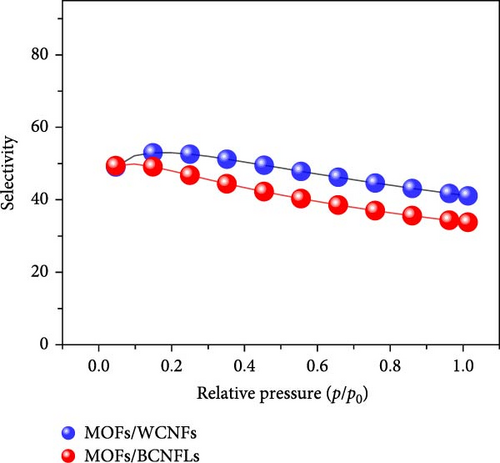
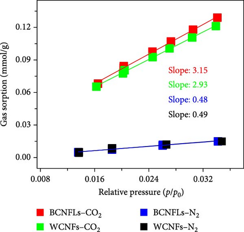
The ratio of Henry’s constants of CO2 (kx) and N2 (ky) were used to calculate the selectivity [52]. The calculated selectivity () was approximately 6.5 and 6 for MOFs/BCNFLs and MOFs/WCNFs, respectively, indicating good CO2/N2 separation potential.
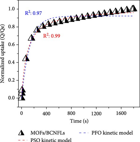
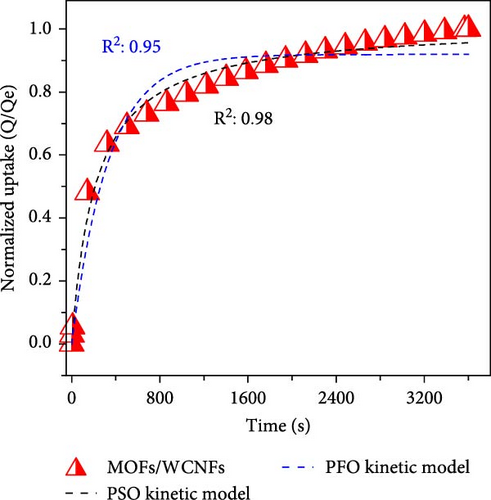
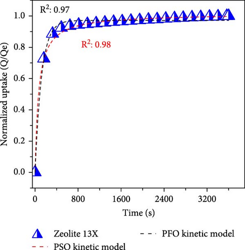
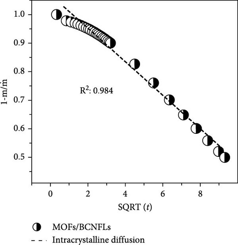
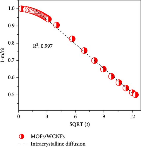
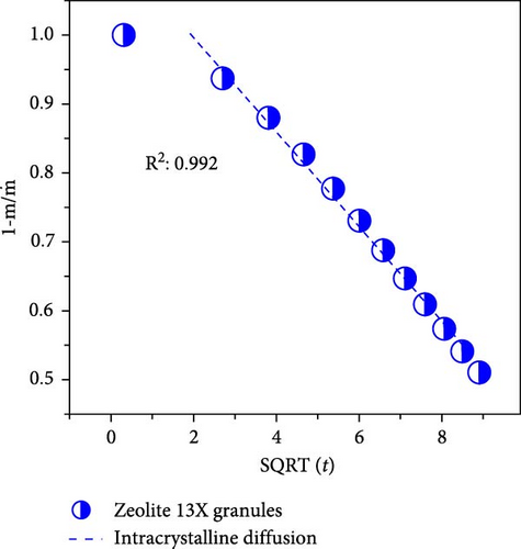
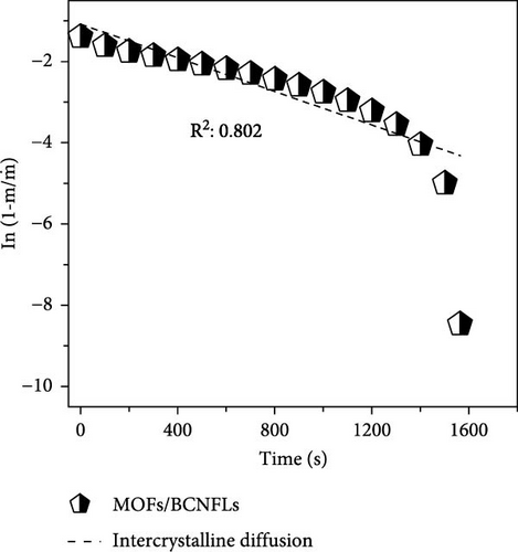
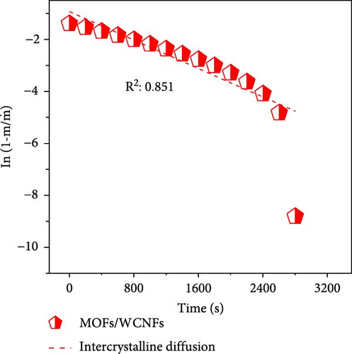
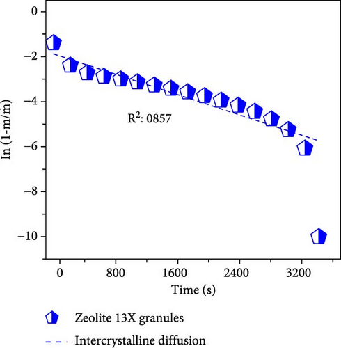
To differentiate the importance of the substrate types for the coating of MOFs over nanofibers, kinetics parameters were estimated by recording CO2 adsorption using TGA-DSC. Figure 5a–c shows the normalized uptake of CO2 versus time to understand the kinetic parameters, which were compared against NaX granules, a standard and commercially used sorbent for CO2 capture applications. The data fitted well with pseudo-first-order (PFO) and pseudo-second-order (PSO) kinetics models as given in equations (5) and (6) [53].
4. Conclusions
The in situ synthesis of Cu-MOFs grafted onto various cellulose substrates was successfully achieved via the solvothermal method. SEM microscopy confirms the uniform coating of MOFs particles on different CNFs. The CO2 sorption capacity of MOFs/BCNFLs and MOFs/WCNFs sorbents was approximately 1 and 1.19 mmol/g, respectively, which was directly proportional to the MOFs loading on the substrates. Both sorbents maintained consistent performance for four consecutive cycles, indicating stability and regenerability. The sorption was micropore-controlled with a physisorption mechanism, as highlighted by the lower enthalpy of adsorption and diffusion model fittings. The MOFs/BCNFLs exhibited superior CO2 sorption kinetics compared to MOFs/WCNFs, underscoring its potential for practical applications. The diffusion coefficient of MOFs/BCNFLs was 25% higher than that of MOFs/WCNFs, resulting in enhanced sorption kinetics. Additionally, the rate constant of MOFs/BCNFLs was 2.2 times higher than that of MOFs/WCNFs, further reinforcing its efficiency. These findings highlight the potential of MOFs-coated cellulose substrates for practical CO2 capture applications.
Conflicts of Interest
The authors declare no conflicts of interest.
Funding
This work was funded by Vetenskapsrådet (Grant 2018-04407) and SUN-Natural Resources for Sustainability Transitions, Luleå tekniska universitet (Grant LTU-4961-2022).
Open Research
Data Availability Statement
The data that support the findings of this study are available from the corresponding author upon reasonable request.


