Advancing Piezoelectric Wind Energy Solutions: Evaluating Turbine Rotor Blade Designs for Sustainable Smart City Infrastructure
Abstract
Smart energy solutions are critical to the development of smart cities, aligning with Saudi Arabia’s Vision 2030, which aims to transform urban centers through sustainable technologies. This transformation, driven by the widespread use of smart sensors for traffic regulation, parking systems, and environmental monitoring, requires efficient, eco-friendly energy sources to reduce reliance on conventional batteries. In the city of Hail, wind energy presents a promising opportunity to generate clean power for low-energy sensors. This paper introduces a compact small wind energy harvesting system (SWEHS) that integrates piezoelectric and electromagnetic mechanisms designed specifically for powering sensors in low-wind environments. The harvester consists of two concentric rings: an inner rotator ring containing four equally spaced permanent magnetic plates arranged in a symmetrical pole configuration to minimize starting torque and improve power generation at low wind speeds. The outer ring incorporates four piezoelectric benders coupled with magnetic plates, converting mechanical energy into electrical power. Experimental results show that the Savonius rotor design outperforms Helical Savonius and Cup rotors, achieving a peak power output of 0.767 mW at a resistive load of 15 kΩ and wind speed of 6.5 m/s. This design demonstrates superior efficiency in decentralized energy production, making it a viable solution for sustainable, low-power energy harvesting in smart city infrastructure.
1. Introduction
In the age of urbanization, smart cities, integrating advanced technologies for sustainability, efficiency, and enhanced living, are pivotal. Smart energy management is crucial for environmental resilience [1]. In line with the Saudi Vision 2030 objectives, Saudi authorities have embarked on an ambitious journey toward transforming their cities into smart urban hubs, integrating cutting-edge technologies to enhance efficiency, sustainability, and quality of life [2]. The implementation of smart city projects marks a shift toward holistic urban planning, prioritizing energy-efficient solutions. Yet, as smart cities utilize sensors for various applications such as traffic regulation, parking management, and weather monitoring, their sustainability hinges on energy sources. Traditionally reliant on grid electricity or batteries, posing challenges related to limited operating range, frequent replacements, and environmental implications associated with disposal [3, 4]. To promote sustainable urbanization, exploring clean energy alternatives like solar [5] and wind [6, 7] power is imperative. In this context, Hail City presents a great opportunity for leveraging its abundant wind resources [8] to generate clean electricity to power sensors and enhance sustainability. By deploying small-scale wind energy harvesters, the wind’s kinetic energy can be converted into sustainable electrical power, providing a decentralized energy source for low-power sensors citywide.
Wind energy, which presents a significant potential as an alternative energy source, has seen widespread adoption for human consumption. According to calculations by Archer and Jacobson [9], global wind power holds a substantial energy potential of ~72 terawatts (TW). Utilizing just 20% of this capacity could meet the entirety of the world’s energy requirements and exceed global electricity demands by over sevenfold (1.6–1.8 TW). Traditionally, wind energy is harnessed through large-scale wind turbines situated in remote locations. These turbines incorporate complex mechanisms, including tall towers, sizable blades, gear systems, speed regulators, as well as magnets and coils for power generation. Rastegar and Murray [10] developed an innovative two-stage rotary generator utilizing magnetic interfaces to facilitate machinery rotation at varying and low speeds. This generator boasts a specific design allowing for the attachment of numerous piezoelectric beams to either a rotor or device frame, enabling simultaneous excitation by wind. In the context of urban wind energy harvesting, Tien and Goo [11] devised a compact wind turbine featuring a piezocomposite generating element (PCGE), effectively converting mechanical energy into electrical power. This device, designed as a low-capacity power generator for urban areas, offers the benefits of lightweight construction, quiet operation, and sensitivity to slight wind movements, along with swift responsiveness to urban wind gusts. The utilization of emerging technologies for harvesting energy to power small electrical devices holds significant promise, including methods such as the piezoelectric transducer [12–14], the triboelectric effect [15], electrostatic induction [16], and others, which effectively capture ambient energy often overlooked. Among these, piezoelectric energy harvesting devices have garnered considerable attention due to their minimal startup power requirements, uncomplicated structure, absence of electromagnetic interference, cost-effectiveness, seamless integration with micro-electro-mechanical systems (MEMSs), and high energy density. Consequently, there is a growing focus among researchers on piezoelectric wind energy harvesting technology, resulting in the generation of numerous scientific findings [17–20].
Zou et al. [21] devised and evaluated a magnetically coupled two-degree-of-freedom (2-DOF) energy scavenger to harness rotational motion, featuring two upside-down piezoelectric cantilever beams with their free ends rotating along a laterally oriented axis. The centrifugal force direction opposes the fixed end’s direction to the free end during rotation. This harvester demonstrates effectiveness in generating output power solely at resonant rotation frequencies around 420 and 550 rpm, yielding power outputs of ~564 μW and 535 μW, respectively. He et al. [22] presented a piezoelectric energy harvester activated by the inertial and magnetic forces of a mass magnet. Their design involves two cantilever-style piezoelectric beams arranged at different angles to the lateral plane to generate torsional deformation and capture energy from rotating equipment. Peak voltage and generated power are achieved at certain resonance speeds, including 150 and 800 rpm. Additionally, they developed another harvester driven by an inertial wheel, featuring magnet coupling and plucking mechanisms. The pressure from the magnetic casing on the rotating rotor stimulates the rectangular piezoelectric element, while magnetic plucking stimulates the circular piezoelectric. This system shows effectiveness at 550 rpm, producing a power output of 0.801 mW [23].
Zhao et al. [24] investigated a novel approach for piezoelectric wind energy harvesting utilizing a magnetically coupled force amplification mechanism. This proposed method demonstrates the capability to harvest energy across a broad range of wind speeds, offering enhanced robustness and reduced resistance during the conversion process. Experimental analysis indicates high reliability and stable performance of the proposed device. Zhang et al. [25] proposed a wind energy harvesting device employing a rotary table to impact a piezoelectric beam. Wind-blown blades drive the rotation of the device, converting wind energy into vibrations of the piezoelectric module through magnetic excitation or direct contact. Experimental tests yielded a maximum output power of 2566.4 mW for the entire device. Wu et al. [26] introduced a piezoelectric magnetic energy harvester tailored for rotating mechanisms. The vibration of the piezoelectric cantilever beam is induced by noncontact magnetic excitation, offering the advantage of reduced frictional losses. Experimental measurements confirm its high-power generation capability.
Despite the success of energy harvesting utilizing cantilever-type piezoelectric beams to generate voltage and power from rotational energy, practical implementation faces challenges. Traditional linear piezoelectric harvesters achieve maximum power output primarily at their resonant frequency, often requiring tuning for optimal performance. To address this limitation, researchers have explored nonlinear energy harvesting approaches, such as bistable and tristable configurations, which enable broader frequency response and enhanced energy conversion [27, 28]. However, these methods are primarily suited for vibration-based harvesters. Additionally, investigations have revealed that the energy density of piezoelectric beam-based energy harvesters excited by vibration and inertial mass is comparatively low, approximately half that of compressive-type harvesters [29, 30]. Consequently, researchers have explored the development of piezoelectric harvesters with compressive-based configurations. Kan et al. [31] introduced an energy harvester employing rotational magnets interacting with multiple piezoelectric discs, resulting in periodic rather than harmonic excitation forces. Narolia, Gupta, and Parinov [32] proposed an energy harvester featuring coaxial parallel plates, which generates strain in piezoelectric patches through the repelling force of rotating magnets. Despite its ability to produce voltage, this harvester’s power generation remains relatively low. Zhao et al. [33] presented a waterproof hybrid wind energy harvester integrating magnetic coupling and force enhancement methods on piezoelectric and electromagnetic transducers. The stiff nature of the piezoelectric material in the flex-tension transducer design causes resistance torque when the magnets pull the transducer in the same direction as the rotational motion.
Within the context of wind energy harvesting utilizing the piezoelectric effect, existing literature reveals a predominant focus on cantilever beam models, which exhibit lower energy density compared to compressed-type harvesters, alongside higher costs. Moreover, most studies primarily concentrate on refining harvester mechanisms and operations, neglecting optimal design enhancements for the harvester fan to effectively capture wind energy across a broad frequency spectrum. Consequently, piezoelectric energy harvesters encounter numerous challenges, including vibration energy dissipation, cost inefficiencies hindering their viability as battery replacements for powering small sensors, and suboptimal performance at low speeds.
To overcome these challenges, we propose a novel rotary piezoelectric vibration energy harvesting mechanism employing magnetic coupling with a piezoelectric bender. We demonstrate its cost-effectiveness and availability in achieving sustainable energy objectives. The operation of the piezoelectric harvester entails a rotating fan driving the shaft and subsequent rotation of the harvester’s components. During rotation, built-in piezoelectric bending elements within the harvester are excited by magnetic repulsion or attraction forces. The maximum magnetic force remains constant regardless of operating conditions, ensuring a robust design with improved equivalent piezoelectric coefficient and reliable operation across various frequencies. We explore three different rotating fan shapes to optimize performance across a wide range of wind energy inputs, ensuring energy production under diverse conditions. Additionally, we discuss the effect of magnetic arrangement mode and key structural parameters. Laboratory experiments are conducted to assess the performance of the proposed harvester.
2. Design and Operating Principle
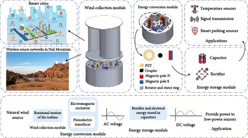
The designed harvester provides power to environmental monitoring sensors in Hail City. It consists of two main components: (1) a wind harvesting system that tests three distinct rotor types and (2) an energy conversion unit, as illustrated in Figure 1. The harvester can be installed in various locations across Hail City, both within urban areas and in remote regions, to transform wind energy into electrical power for supporting low-power sensors.
2.1. Wind Harvesting System
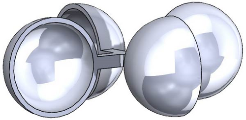
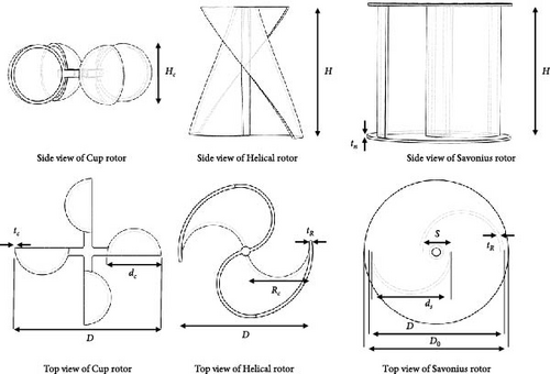
In this section, we focus on testing three distinct types of wind rotors—Savonius rotor, Helical Savonius rotor, and Cup rotor—to explore their potential in wind piezoelectric harvesting applications. These rotor types were selected due to their widespread use in similar energy harvesting systems, as evidenced by numerous studies in the field [34–36]. The objective of our work is to investigate and compare their performance under identical environmental conditions to determine which rotor design is most efficient for harnessing wind energy, particularly in low-power applications.
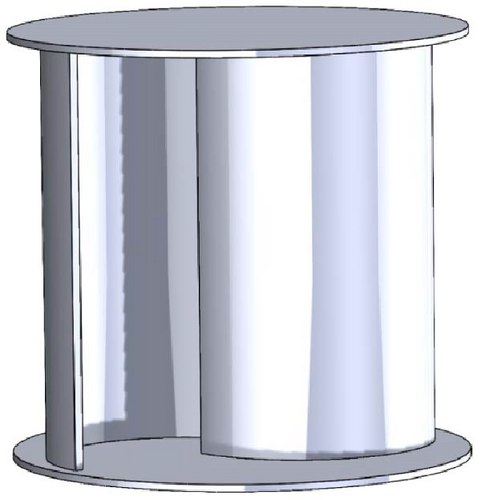
The Savonius rotor is known for its simplicity and ability to capture wind from all directions, making it effective at low wind speeds and in turbulent conditions. However, it may face limitations due to higher resistive torque at higher wind speeds [37].
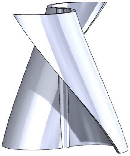
The Helical Savonius rotor offers a smoother, more continuous rotation, reducing pulsating torque and mechanical stress. Its Helical design provides better efficiency across a range of wind speeds, balancing performance in low-to-moderate wind conditions [38, 39].
The Cup rotor, often used in anemometers, is highly sensitive to low wind speeds due to its low starting torque, allowing it to overcome resistive forces easily. This makes it particularly suited for areas with low wind energy [35].
In previous studies on piezoelectric wind energy harvesting, different rotor shapes, such as Savonius and Cup rotors, have been used, but most studies do not provide a clear justification for their selection. The only work we found that examined rotor geometry focused on varying the number of blades rather than comparing different rotor types under the same conditions. To address this gap, we systematically evaluated three widely used rotor designs—Savonius, Helical Savonius, and Cup—under identical conditions to assess their impact on power generation. Other designs, such as the H-Darrieus rotor, were also tested but were found to be unsuitable due to their poor rotation performance at low wind speeds. By comparing these rotors, we aim to identify the most efficient design for generating power in different wind scenarios, helping to optimize piezoelectric energy harvesting. The 3D models of the three rotor shapes, all with the same overall diameter (D), are displayed in Figure 2. Figure 3 highlights the configurations of the Cup rotor, Helical Savonius rotor, and Savonius rotor, while Table 1 summarizes their key functional parameters. This research focuses on examining how the different rotor shapes, including Cup, Helical Savonius, and Savonius, impact the performance of wind energy harvesting, particularly in optimizing power output.
| Rotor type | Diameter of rotor (D) (mm) | End plate diameter (D0) (m) | Height of rotor (H) (m) | Rotor overlap (S) (m) | Rotor swept area (As) (mm2) | Rotor overlap ratio (OL) | Aspect ratio (AR) | Blade thickness (t) (mm) |
|---|---|---|---|---|---|---|---|---|
| Savonius | 87 | 95.7 | 87 | 20 | 3784.5 | 0.23 | 1.626 | 2 |
| Helical | 87 | — | 87 | 0 | 3784.5 | 0 | 2 | 2 |
| Cup | 87 | — | 40 | — | 3784.5 | — | 0.459 | 2 |
2.2. The Energy Conversion Module
This study builds on a piezoelectric energy harvester previously proposed in our earlier work [40]. Initially, the concept was developed to capture vehicle vibration energy through a regenerative suspension system. In this research, the focus shifts to using piezoelectric transducers for energy harvesting, specifically adapting the piezoelectric harvester design for wind energy applications. The design features two concentric rings integrated with energy-scavenging components. Rectangular permanent magnetic plates are symmetrically mounted on the inner surface of the stator ring, positioned between the stator ring and these magnetic plates. A 3D-printed circular plate acts as a connector between the magnetic plates and the piezoelectric benders, causing them to undergo periodic compression. As shown in Figure 4, the symmetric arrangement of the magnetic plates on the outer surface of the rotor ring allows for charge extraction. Figure 5 illustrates the deformation of a single piezoelectric bender during a full rotation cycle of the rotor with an N–S–S–N magnetic configuration. As the rotor magnets pass over the stator, they generate alternating repulsion and attraction forces. At positions A and D, repulsion forces cause the bender to bend downward, while at B and C, attraction forces pull it upward. This periodic deformation results in the characteristic voltage pattern shown on the left, where maximum voltage occurs at the transition points between attraction and repulsion, and minimum voltage correspond to peak bending positions. Both rings are 3D-printed, with disk supports on the stator ring’s inner surface enabling the attachment of the piezoelectric elements. This design converts wind kinetic energy into rotational energy, driving the shaft and rotor ring of the harvester. The rotation generates periodic repulsive magnetic forces, compressing the piezoelectric benders. By fixing the piezoelectric pieces at the ends of their disks and utilizing connecting elements between the magnets and piezoelectric components, deformation occurs at the center, enhancing flexion and enabling higher voltage generation.
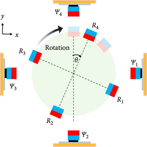
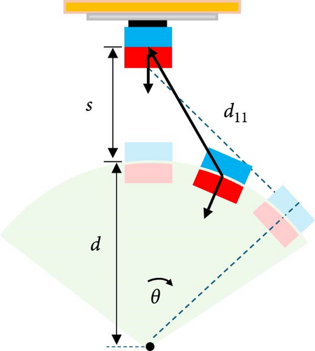
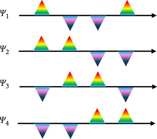

Table 2 outlines the critical parameters that influence the performance of the wind piezoelectric harvester, covering all relevant factors unless noted otherwise. The arrangement of the magnets is a key determinant of the harvester’s efficiency, particularly in terms of magnetic coupling and power output.
| Harvester parameter | Value (mm) |
|---|---|
| Piezoelectric disk bender | |
| Brass diameter | 35 |
| Ceramic diameter | 25 |
| Overall thickness | 0.55 |
| Brass thickness | 0.3 |
| Magnet | |
| The residuals flux density Br | 1.3 |
| Magnet’s thickness tm | 3.175 |
| Magnet’s width wm | 9.525 |
| Magnet’s length lm | 25.4 |
| Magnet’s volume vm | 768.14 |
3. Theoretical and Simulation Analysis
3.1. Magnetic Excitation Analysis
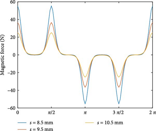
The magnetic force is computed using MATLAB, with parameter values derived from the material properties and dimensions outlined in Table 2. In the symmetrical arrangement of rotating magnet pairs (R1 and R2, R3 and R4), opposite magnetic forces consistently arise during rotation. Specifically, two pairs experience attraction while the other two are repelled. This configuration helps reduce magnetic resistance torques that could otherwise disrupt the rotation. Furthermore, as the magnets on the rotating ring approach the closest point to the magnets on the stationary ring (ψ1 and ψ3, ψ2, and ψ4), their magnetic poles either oppose each other or align. As a result, the directions of the attractive or repulsive magnetic forces align with the deformation directions of the piezoelectric transducers. In the magnetic configuration used in this study, the static and rotating magnets are oriented with their poles facing each other, as shown in Figure 4a,b. The magnetic poles of the stator magnets (ψ1–ψ4) are all north (N), while the poles of the rotating magnets (R1 to R4) are arranged as north, north, south, and south, respectively. When magnetic repulsion causes piezoelectric deformation, a positive voltage is generated, whereas magnetic attraction leads to a negative voltage, as shown in Figure 4c. The magnetic flux density simulation results, based on this arrangement using COMSOL, are illustrated in Figure 6, while Figure 7 illustrates the magnetic forces acting on the stator magnet Y1 throughout a complete rotational cycle, with varying separation distances between the stationary and rotary magnets. The angle, ranging from 0 to 2π radians, represents the full rotation, during which the magnetic force fluctuates between positive and negative values, reflecting alternating attractive and repulsive interactions. The simulations were performed at three different separations: 8.5, 9.5, and 10.5 mm. The peak magnetic forces measured for these distances are 55.21 N, 36.52 N, and 25.12 N, respectively. At smaller separations, the magnetic forces are stronger, as seen in the higher peaks and deeper troughs for the 8.5 mm curve compared to the 9.5 and 10.5 mm curves. As the separation increases, the magnitude of the magnetic force diminishes, indicating a reduction in magnetic interaction with greater distance. The shape of the curves highlights the nonlinear relationship between magnetic force, angle, and separation, with the force decreasing as the magnets move further apart. This behavior aligns with the characteristics of dipole–dipole interactions, where magnetic field strength weakens with distance.

3.2. ANSYS Fluent Simulation
In this work, ANSYS FLUENT was employed to assess the aerodynamic performance of three different vertical-axis wind turbines (VAWTs): the Savonius, Helical Savonius, and Cup rotors, as depicted in Figure 2. The simulations were performed using unidirectional fluid-solid coupling, meaning only the influence of the fluid (air) on the rotor blades was considered without feedback from the solid structures. The relevant parameters for the simulation model are provided in Table 1. To approximate real-world conditions, the model was constructed under scenarios closely matching the proposed system. However, certain components, such as the shaft, magnetic forces, and installation base, were excluded from the analysis, which may introduce some deviations in the aerodynamic results. The wind velocity was varied between 4.5 and 8.5 m/s. For the fluid-solid coupling analysis, the fluid (air) was defined with a viscosity of 1.7894e–05 kg/m-s and a density of 1.225 kg/m3. The meshing of the fluid domain used a default mesh configuration with an element size of 3.5 mm. The surface quality profile of the watershed is presented in Figure 8.
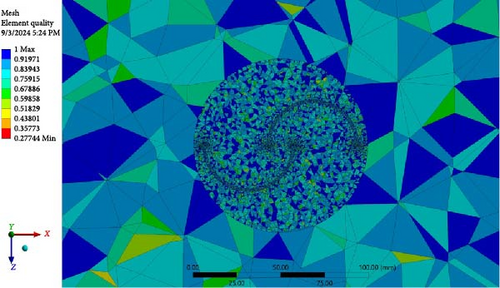
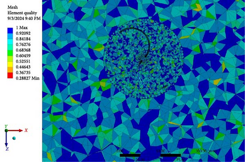
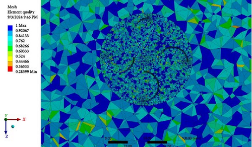
The simulation domain is set to a basic area of 150 x 150 x 445 mm3. The k-epsilon (two equations) turbulence model with realizable and enhanced wall treatment was employed to simulate the wind turbines with different rotor geometries separately. As shown in Figure 9a1–d1, the pressure distribution within the domain of the Savonius wind turbine is depicted. With an increase in wind speed at the basin inlet, the pressure distribution around the wind turbine increases proportionally. Similarly, Figure 9a2–d2 illustrates the velocity variation within the basin for the Savonius rotor. The results clearly indicate that as the inlet velocity increases, the flow velocity on both sides of the turbine also rises. Figures 10 and 11 present the calculated pressure distribution and velocity variation for the Helical Savonius and Cup rotors, respectively. The observed variations are comparable to those of the Savonius turbine, showing a consistent trend across the different rotor types. These results align well with the expected outcomes and are crucial for supporting the continuation of the experimental study.


4. Experimental Setup
This section describes the experimental setup used to evaluate the performance of the wind energy piezoelectric harvester, as depicted in Figure 12. The device was tested in a controlled environment using a wind tunnel (C15-10, Armfield, UK) that allowed precise regulation of airflow speeds, adjustable via computer control, with velocities reaching up to 34 m/s. A digital anemometer (TA8161, TASI, China) measured airflow velocity with an accuracy of ±3%, ranging from 0.3 to 30 m/s. The prototype was securely positioned at the center of the wind tunnel’s test section using a circular hatch and quick-release clamps to ensure stability and reduce experimental error. Tests were conducted across a wide range of wind speeds to evaluate the harvester’s stability and response to varying conditions. A laser tachometer (87304-00, Cole-Parmer, US) was used to measure the turbine’s rotational speed, providing an accuracy of ±1% for readings between 6 and 8300 rpm. The output voltage of the harvester was monitored using a digital oscilloscope (SDS 1104X-E, Siglent Technologies Co. Ltd, China).
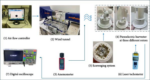
The experiments were designed to examine how different wind speeds and structural parameters influence the power generation capacity of the harvester, with a particular focus on the performance of various rotor shapes. Tables 1 and 2 provide detailed specifications of the harvester. The four piezoelectric benders in the energy harvester were connected in series or parallel to measure the generated current and voltage. The rotating ring featured an outer diameter of 84 mm, and the harvester used commercially available piezoelectric bender disks made of PZT (lead zirconate titanate). Strong Neodymium magnets (grade N42) from K&J Magnetics, Inc. were used as the rectangular permanent magnetic plates in the setup.
5. Results and Discussion
In the experimental setup, the open-circuit RMS voltage was measured for different separation distances between magnets, with all four piezoelectric disks connected in series and a constant wind speed of 5.5 m/s. It should be noted that the turbine blade used is the Savonius wind turbine. As shown in Figure 13, at a separation distance of 8.5 mm, the RMS voltage reached a maximum value of 18.21 V. When the distance between the magnets was increased to 9.5 mm, the RMS voltage decreased to 13.3 V and further dropped to 6.958 V at a separation distance of 10.5 mm. These results indicate a clear decreasing trend in voltage output as the distance between magnets increases. This behavior agrees with the simulation results depicted in Figure 7, where a reduction in the magnetic separation resulted in higher magnetic forces. These forces caused greater deformation in the piezoelectric materials, leading to a higher voltage output, thereby supporting the experimental findings. While reducing the magnet separation distance increases voltage output due to stronger magnetic interactions, it also leads to higher resistive magnetic torque, making rotor startup more difficult at low wind speeds. At 8.5 mm, the highest voltage output was achieved; however, the rotor required either higher wind speeds or an initial push to initiate rotation. In contrast, at 10.5 mm, the voltage output was significantly lower, but the rotor exhibited better self-starting behavior, especially at lower wind speeds. This trade-off suggests that the optimal separation distance depends on the intended operating conditions, whether the focus is on maximizing power output or ensuring a reliable start in low-wind environments.
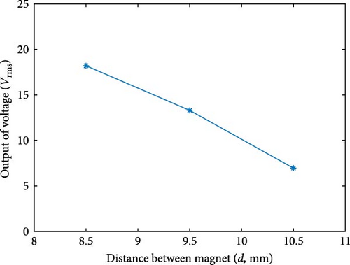
Figure 14 presents the open-circuit voltage outputs of the individual piezoelectric bender disks (PZT1, PZT2, PZT3, and PZT4) at a wind speed of 5.5 m/s, with an 8.5 mm gap between the rotating and static magnets in a Savonius turbine setup. The results reveal distinct behaviors among the piezoelectric disks: PZT1 and PZT2 are influenced by repulsion forces, while PZT3 and PZT4 experience attraction forces. The voltage waveforms align with the expected patterns based on the magnetic configuration. However, there is a clear difference in the peak-to-peak voltage levels, with PZT1 and PZT2 showing similar values while PZT3 and PZT4 exhibit slightly higher peaks.
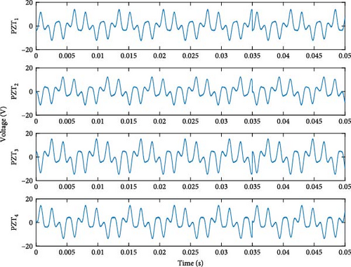
These variations suggest potential factors affecting the interaction between the magnetic configuration and the piezoelectric elements. Possible explanations include an uneven distribution of magnetic forces, differences in the material properties or dimensions of the piezoelectric disks, or mechanical coupling between the rotating and static components that influence force transmission. Additionally, machining imperfections may have caused slight variations in the magnet spacing, ideally set at 8.5 mm. Variations in the thickness of the adhesive used to attach the piezoelectric disks to the magnets could also affect the separation distance. Further investigation and design optimization, along with a detailed analysis of magnetic field distributions and piezoelectric responses, are necessary to address these discrepancies. Starting from Figure 15, the voltage, current, and power measurements represent the combined output of all four piezoelectric benders, which are connected in parallel to optimize the total power output. This configuration ensures that the current contributions from each PZT are summed while maintaining a consistent voltage level across the system. The transition from individual responses in Figure 14 to the total system response in Figure 15 is clarified to provide a more comprehensive understanding of the harvester’s overall performance under different load conditions.
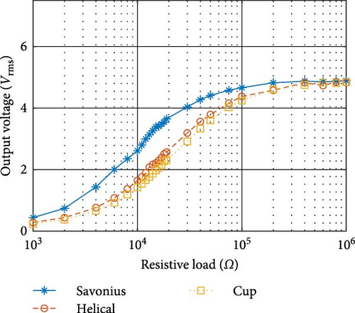
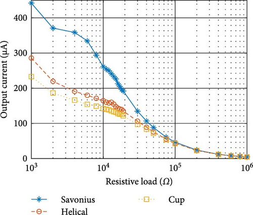
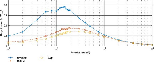
In Figure 15, the experimental results illustrate the relationship between resistive load and three key electrical output parameters: RMS voltage, output current, and generated power of the piezoelectric wind energy scavenger using different turbine blade configurations—Savonius, Helical, and Cup. The piezoelectric bender disks were connected in parallel and tested across various wind speeds, with a fixed wind speed of 6.5 m/s and a separating distance of 8.5 mm between the two permanent magnets. Figure 15a demonstrates how the output voltage increases with resistive load, particularly for the Savonius configuration, which outperforms the Helical and Cup turbines, achieving the highest voltage values at higher resistances. In contrast, Figure 15b shows the output current decreasing as resistive load increases, with Savonius consistently providing higher current values compared to the other configurations. Figure 15c highlights the generated power as a function of resistive load, where the Savonius turbine peaks at a resistive load of 15 kΩ, producing a maximum power output of 0.767 mW. Both the Helical and Cup turbines share the same optimal resistive load of 18 kΩ, at which their peak power outputs were 0.350 mW and 0.286 mW, respectively. These findings suggest that the Savonius turbine offers superior performance in terms of voltage, current, and power output when compared to the other configurations, particularly at higher resistive loads. The distinct behaviors of the turbine designs provide insight into the optimization of wind energy harvesters for different load conditions. Further analysis could focus on understanding the underlying mechanisms behind the varying performance of these turbine designs.
Figure 14 presents a comprehensive analysis of the output performance of the piezoelectric scavenging system using three different wind turbine designs: Savonius, Helical, and Cup. Figure 16a the rotational speeds of all three turbine designs are shown as a function of wind speed. At the maximum wind speed of 8.5 m/s, the Savonius turbine achieves a peak rotational speed of 1684 rpm, significantly outpacing the Helical and Cup turbines, which reach 928 rpm and 712 rpm, respectively. This marked difference illustrates the superior aerodynamic efficiency of the Savonius turbine in converting wind energy into rotational motion compared to the other designs. As the wind speed increases, all turbines show a proportional rise in rotational speed, but the Savonius rotor consistently maintains the highest performance while the Cup rotor lags behind.
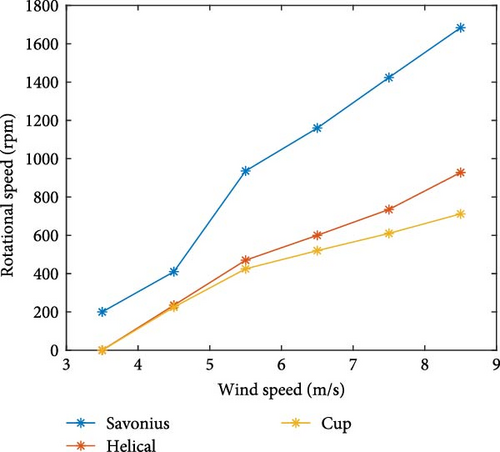
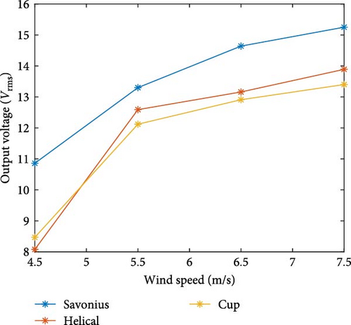
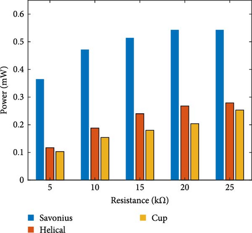
Figure 16b highlights the variation in output voltage (open-circuit) as a function of wind speed. Similar to the rotational speed, the Savonius turbine produces the highest output voltage, peaking at 15.25 V at a wind speed of 7.5 m/s. The Helical and Cup turbines also show increased voltages with higher wind speeds, but their maximum values, around 13.89 V and 13.40 V, respectively, remain consistently lower than the Savonius turbine. This indicates that the Savonius turbine is better suited for converting wind energy into electrical energy when no load is applied, making it more effective at voltage generation. While rotational speed increases significantly with wind speed, the rise in output voltage is more gradual. We hypothesize that this behavior is influenced by both the nature of magnetic excitation and the response time of the piezoelectric elements. Due to the N–N–S–S magnetic arrangement, each piezoelectric disk undergoes two consecutive compression cycles followed by two consecutive tension cycles. At lower rotational speeds, the benders have enough time to fully deform and return to their neutral position before the next excitation. However, at higher speeds, the time between successive magnetic interactions becomes shorter, preventing the benders from fully recovering before the next cycle. This results in incomplete deformation, reducing the strain experienced per cycle and leading to a diminishing rate of increase in voltage output. Additionally, the internal damping of the piezoelectric material further contributes to energy loss at high excitation frequencies. These factors may explain why the voltage curve in Figure 16b does not rise as sharply as the rotational speed curve in Figure 16a.
Figure 16c focuses on the generated power output as a function of external load resistance at a fixed wind speed of 5.5 m/s. Once again, the Savonius turbine leads in performance, producing the highest power output across a range of resistive loads. It achieves a peak power of around 0.6 mW at a resistance of 15 kΩ. The Helical and Cup turbines, while showing a similar trend, deliver significantly lower power output, with the Helical turbine reaching about 0.35 mW and the Cup turbine peaking around 0.25 mW at the same load resistance. These results underscore the efficiency of the Savonius turbine, particularly at converting wind energy into electrical power under load conditions, outperforming the other designs across all tested parameters. Overall, the figure highlights the superior performance of the Savonius turbine in the piezoelectric wind energy scavenging system. It consistently generates higher rotational speeds, voltages, and power outputs compared to the Helical and Cup turbines, demonstrating its potential for more effective energy harvesting applications.
Figure 17 illustrates the open-circuit voltage spectra generated by a single piezoelectric bender at various wind speeds using the Savonius wind turbine with a magnet separation distance of 9.5 mm. The plot shows voltage waveforms at wind speeds of 3.5, 4.5, 5.5, and 6.5 m/s. As the wind speed increases, the frequency of the voltage oscillations becomes more rapid and consistent, indicating higher excitation rates at elevated wind speeds. At 6.5 m/s, the voltage waveform becomes more periodic with a higher frequency compared to lower wind speeds, demonstrating the direct influence of wind speed on the frequency and magnitude of the voltage output. The peaks in voltage amplitude also tend to increase with wind speed, reaching values as high as 25 V at the highest wind speed. This data provides insight into how the piezoelectric bender responds to increasing aerodynamic excitation and the resulting voltage generation under varying wind conditions.

The performance of our piezoelectric energy harvester demonstrates a competitive edge when compared to other studies in the field, as shown in Table 3. While some of the previously reported designs achieved higher power outputs, many of them utilized expensive piezoelectric materials and sophisticated fabrication techniques, leading to significantly higher costs. In contrast, our proposed harvester achieves comparable performance using cost-effective, commercially available piezoelectric disk benders, which are priced at approximately $1 per unit. The overall cost of our harvester remains under $40, making it a practical and scalable solution for powering small sensors in urban environments. Additionally, the simple structure and modular design allow for easy deployment and maintenance, further enhancing its feasibility for real-world applications. Despite the simplicity and low cost of our design, utilizing a piezoelectric disk bender that costs less than a dollar, we achieved a power output of 0.767 mW at a wind speed of 6.5 m/s. This output is notable given that more sophisticated designs often involve higher-cost piezoelectric materials, with expenses ranging from $40 to $200 [45]. The results underscore the effectiveness of our simple and affordable system, positioning it as a viable alternative for cost-effective energy harvesting applications.
| Reference | Materials | Speed | Power (mW) | Structural design | Advantages | Disadvantages |
|---|---|---|---|---|---|---|
| Zhang et al. [25] | Piezoelectric (PVDF) beam | 7 m/s | 0.8 | Rotating fan blade with impact-induced PVDF beam vibration | High output with tunable structural parameters, efficient at various wind speeds | Decreased efficiency at very high wind speeds due to impact frequency limitations |
| Stamatellou and Kalfas [42] | Piezoelectric film (PVDF) | 1584 rpm | 0.00375 | Cantilever beam with isolation from base vibrations | Reduces unwanted structural vibrations | Very low power output |
| Hu et al. [43] | Piezoelectric layer | 7 m/s | 0.039 | Circular cylinder with vortex-induced vibrations | Aerodynamic enhancements improve efficiency | Limited power output at lower wind speeds |
| Zhao et al. [24] | Piezoelectric flextensional transducer | 7 m/s | 1.32 | Magnetically coupled flextensional transducer with rotating magnets | High robustness, force amplification enhances output | Complex structure, high manufacturing precision required |
| Na et al. [44] | Piezoelectric (PZT) sheet | 6.5 m/s | 5.84 | Magnetically coupled piezoelectric bimorph cantilever array | High-power output, low startup resistance | Requires careful magnet arrangement and complex manufacturing |
| Current work | Piezoelectric (PZT) disk bender | 6.5 m/s | 0.767 | Magnetic coupling with piezoelectric benders and rotor-driven actuation | High-power density, cost-effective, scalable, robust under varying wind conditions, and effective at low wind speeds | High-resistive torque at narrow magnet distances, affecting startup at low wind speeds |
6. Conclusion
This study presents a novel approach to piezoelectric wind energy harvesting designed to power low-energy sensors within smart city infrastructures. The proposed small wind energy harvesting system (SWEHS) combines piezoelectric and electromagnetic mechanisms and evaluates three rotor designs—Savonius, Helical Savonius, and Cup Rotors—to determine the most efficient for low-wind environments, such as Hail City. A combination of theoretical analysis, simulation, and experimental validation demonstrates that the Savonius rotor provides superior performance in terms of power generation, rotational speed, and voltage output, particularly at low wind speeds.
The experimental results underscore the potential of the Savonius rotor for decentralized energy production. A peak power output of 0.767 mW was achieved at a resistive load of 15 kΩ. The optimized interaction between the magnetic forces and piezoelectric benders resulted in efficient energy harvesting, making the system suitable for deployment in urban environments with variable wind conditions. The harvester’s compact and lightweight design allows for easy deployment on streetlights, buildings, and remote sensor networks without significant infrastructure modifications. Its low cost and minimal maintenance requirements make it an attractive solution for smart city applications, contributing to sustainable and self-powered sensor networks.
This research contributes to the development of sustainable, low-maintenance energy solutions for smart cities, supporting global sustainability goals and Saudi Arabia’s Vision 2030. Future work will aim to further optimize the magnetic configuration and piezoelectric elements and explore scalability for larger applications. The insights gained from this study could inform the design of next-generation wind energy harvesters capable of powering a wide range of low-power devices in smart cities.
Conflicts of Interest
The authors declare no conflicts of interest.
Funding
This research has been funded by the Scientific Research Deanship at the University of Ha’il Saudi Arabia through project number (RCP-24 087).
Acknowledgments
This research has been funded by the Scientific Research Deanship at the University of Ha’il Saudi Arabia through project number (RCP-24-087).
Open Research
Data Availability Statement
Data will be available upon request.


