Research and Application of Key Parameters of Entry Formed by Roof-Cutting in Inclined Coal Seam
Abstract
The dynamic and complex stress concentration phenomenon during overburden structure stabilization after inclined coal seam mining significantly affects the surrounding rock stability of gob-side entries. To advance the application of entry formed by roof-cutting (EFR) technology in non-pillar mining, this study systematically investigates the optimal parameter selection for EFR in inclined coal seams. The research methodology includes selecting representative test mines under typical geological conditions and employing theoretical analysis, numerical simulation, and field experiments. First, according to the characteristics of EFR forming process, the design criteria of key parameters are given. Then, based on the swelling characteristics of collapsed rock and sliding instability conditions of overlying strata, theoretical formulas for roof-cutting height and angle are derived. Finally, a mechanical model of the inclined seam roof structure is established to analyze and determine roof and lateral support resistance, with corresponding support parameters proposed and validated through industrial tests. Results demonstrate that scientifically designed roof-cutting parameters, combined with the high pretightening force and constant resistance support of constant resistance and large deformation anchor cables (CRLDA), effectively maintain entry roof stability. Furthermore, two-way energy-gathering blasting technology successfully controls working face pressure, while the EFR gangue retention and temporary support system ensures proper entry formation. These findings confirm the feasibility of implementing EFR-based pillarless mining in inclined coal seams, offering significant theoretical and practical value for China’s safe and efficient mining operations.
1. Introduction
The non-pillar mining technology utilizing entry formation through roof-cutting is a new approach developed by Chinese scholars to maximize resource utilization while minimizing the environmental impact of mining. This modern mining method aims to optimize resource use and environmental protection, serving as a crucial tool for coal enterprises to achieve sustainable development. This technology has been successfully implemented across various mining sites nationwide [1]. It is suitable for developing coal seams of various thicknesses under different roof conditions, including hard, compound, and broken roofs [2]. Furthermore, it can be applied to coal seams with varying dip angles, from nearly horizontal to inclined [3]. The entry formed by roof-cutting (EFR) technology represents a transformative advancement in coal mining methodology, having evolved through three distinct developmental phases. During the initial phase (late 20th – early 21st century), conventional blasting and hydraulic fracturing techniques were predominantly utilized for roadway formation through directional roof strata fracturing, primarily targeting stress concentration mitigation. The post-2010 period witnessed a technological breakthrough with the “110 method” introduced by Academician He Manchao’s research team, which synergistically combined dual-roadway roof cutting with dense-hole presplitting to enable practical pillarless mining. Since 2020, the technology has progressed toward intelligent and environmentally sustainable applications, demonstrating successful implementation in deep mining operations and complex geological conditions. Currently established as a fundamental technology for safe and efficient resource extraction, EFR exhibits superior operational adaptability in contemporary mining practices.
For inclined coal seams, many scholars have carried out researches on surrounding rock control and roadway support of gob-side entry. How to utilize high-strength concrete to support the gob-side entry have been studied [4], and a flexible roadway protection technology was put forward [5]. Systematic roof control technology for gob-side entry retaining in steep coal seam was carried out [6]. The nonuniform deformation instability mechanism of gob-side entry was revealed [7, 8]. The failure law of surrounding rock in inclined coal seam was also proposed [9, 10]. Study on the gob-side entry retaining mining of fully mechanized working face was conducted [11, 12]. It can be seen that there have been many studies on the technology of gob-side entry in inclined coal seams, but there are relatively few studies on the application of non-pillar mining technology utilizing entry formation through roof-cutting in inclined coal seams. Mining inclined coal seams present significant challenges due to complex stress distributions and frequent dynamic disasters, which critically influence the stability of gob-side entry surrounding rock. Notably, collapsed gangue in the goaf substantially impacts the fragmented sidewalls of EFR. Furthermore, the structural configuration of overlying strata in inclined coal seams directly influences the magnitude of strata pressure within the stope. A critical consideration in parameter selection for EFR construction involves identifying and addressing the primary controlling factors governing surrounding rock stability, which must be carefully evaluated based on specific geological structural characteristics. These technical challenges collectively constitute significant constraints for implementing pillarless mining technology using roof-cutting roadway methods in inclined coal seam conditions.
Therefore, this study examines the critical factors in forming entries through roof-cutting in the case of an inclined coal seam. It investigates the use of this technique on steeply angled coal seams. The research findings have significant practical implications for implementing advanced non-pillar mining technology that utilizes entry formation through roof-cutting in coal mines under similar geological conditions.
2. Engineering Geological Conditions of Test Site
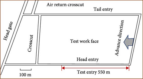
The test face is located at a depth of 220–310 m. It has a strike length of 1050 m, a working face length of 260 m, and a mining length of 850 m. The dip angle of the coal seam in the roof-cutting area ranges from 13° to 31°, with an average of 22°, and the average coal seam thickness is 3.8 m. The layout of the test workface is illustrated in Figure 1.
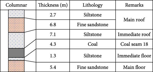
Based on the drilling and geological data obtained from the excavation of the test entry, the roof strata in the mining area of the test workface were found to consist of fine-grained sandstone and siltstone with an integrated contact. The floor rock layer consists of siltstone and fine-grained sandstone. The corresponding column chart is shown in Figure 2.
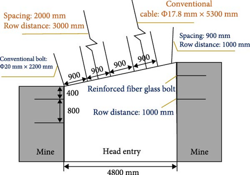
A combination of anchors, mesh, and cables supports the test entry. The top bolt is a left-handed, rebar-free threaded steel bolt measuring φ 20 mm × 2200 mm, with a row distance of 900 mm × 1000 mm. Two rows of φ 20 mm × 1600 mm FRP bolts are arranged on both sides; the first row of bolts is 400 mm from the top, and the second row is 1200 mm from the top, with a spacing of 1000 mm. The anchor cable specifications are φ 17.8 mm × 5300 mm for the prestressed steel strand and 2000 mm × 3000 mm for the rectangular arrangement. The layout of support parameters is shown in Figure 3.
3. Technical Principle and Technological Process of EFR
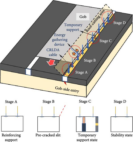
The EFR technology is based on the theoretical foundation of a roof-cutting short-arm beam. It incorporates corresponding patented techniques to form the entry after mining automatically. The basic principle involves enhancing the support of the entry roof with constant resistance and large deformation anchor cables (CRLDA) before mining, which improves the entry roof’s bearing capacity and helps to resist the influence of disturbances during presplitting blasting and mining [13]. Once the roof reinforcement is completed, directional presplitting technology is applied to presplit the roof on one side of the entry near the gob, optimizing the stress environment of the surrounding rock of the entry [14]. During coal mining, the roof of the gob collapses along the cutting line. Specific entry protection measures are implemented so that the caving gangue can automatically form one side of the entry, ultimately realizing the automatic formation of the reserved entry after mining [15]. The technical principle of EFR is illustrated in Figure 4.
This technology preserves a mining entry in the working face for use in the subsequent mining section, eliminating the need to retain coal pillars throughout the mining process [16]. As a result, there is no coal pillar loss during working face mining, leading to an improved coal recovery rate. The process consists of three stages: preparation, mining, and stabilization. Different construction procedures and corresponding technical systems are utilized in each stage [17]. For more detailed information about the technological system and functions of automatic EFR, please refer to Table 1 [18].
| Stage | Process | Technical system | Function |
|---|---|---|---|
| Preparation | Support and roof cutting | CRLDA, two-way energy gathering device | Enhance the bearing capacity of roof strata, optimize the stress environment of entry surrounding rock |
| Mining | Maintenance of entry | Temporary support system | Reduce the intensity of mining stress caused by main roof rotation |
| Stabilization | Mine pressure monitoring | Mine pressure system | Real-time monitoring of mine pressure data to ensure the stability of entry |
3.1. Key Technology of EFR
3.1.1. Constant Resistance and Large Deformation Anchor Cable
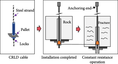
To ensure the successful implementation of non-pillar mining technology by EFR, various patented technologies and products are utilized. These include a CRLDA, a two-way energy gathering device, and a temporary support system. The constant resistance large deformation anchor cable is designed to address the large deformation of surrounding rock during mining [19]. It provides high pretension to the supporting rock mass and accommodates the large deformation of the surrounding rock. During mining, the entry roof is deformed due to mining disturbances. When the constant resistance device reaches the set threshold, the casing of the device moves down to release part of the pressure of the rock mass while maintaining the support resistance and stability of the surrounding rock. The basic principle is shown in Figure 5.
3.1.2. Two-way Energy Gathering Device
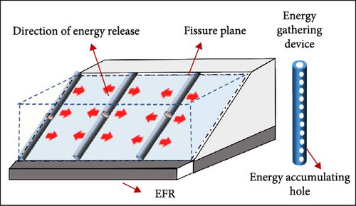
The two-way energy-gathering device is a concentrated blasting device developed based on rock’s compressive and tensile characteristics. It is designed to release impact energy produced by blasting along a specified direction, promoting the rock mass to produce cracks in that direction. After blasting with the blasting material filled in the energy-gathering device, the blast wave is released along the energy-gathering direction, creating an initial crack in the rock mass. Simultaneously, the gas wedge produced by the blast exerts a tensile effect on the rock mass, producing a crack surface along the initial crack direction. The basic principle is illustrated in Figure 6.
3.1.3. Temporary Support System
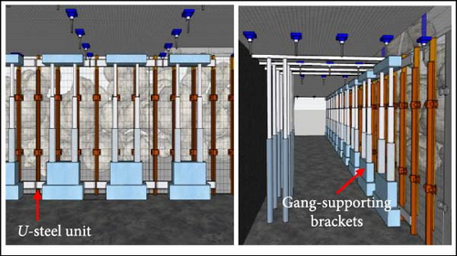
A temporary support system has been developed for EFR technology to accommodate varying coal seam thicknesses and mining conditions. The system combines roof-cutting support and a single prop to form the corresponding support system, as illustrated in Figure 7.
4. Analysis of Key Parameters
4.1. Design Criteria and Key Parameters
The factors that influence the parameter design of EFR are mainly divided into the distribution of roof strata in the working face, coal thickness and mining height, and fault distribution. In engineering design, the engineering zoning baseline is first established based on the importance of the various influencing factors. The principle is whether the initial collapse of the rock mass in the cutting height fills up the mined space, and then the engineering zoning is carried out. Finally, the roof-cutting and support parameters are scientifically determined to ensure the successful implementation of EFR. The baseline is the fundamental parameter for determining the roof-cutting height. During the design phase, this baseline value primarily ensures adequate backfilling of the goaf with collapsed rock. Under standard geological conditions without significant structural discontinuities, the baseline directly corresponds to the optimal roof-cutting height. However, when weak structural planes or fault systems are identified within the proximal rock strata, the cutting height requires adjustment based on site-specific geological characteristics to guarantee effective strata caving performance. The main design parameters and flow are depicted in Figure 8.

The process of EFR construction can be divided into three main stages, with the primary engineering parameters concentrated in the first two stages. The key parameters include constant resistance anchor cable support parameters and roof-cutting parameters in the preparation stage, as well as temporary support and gangue support parameters in the mining stage. Scientifically determined the key parameters were crucial for ensuring the overall stability and effectiveness of the EFR.
4.2. Determination of Key Parameters
4.2.1. Roof-Cutting Height
The roof of the entry in the test area is mainly composed of siltstone. The angle of the coal seam varies greatly. The rock mass within the cutting height range should be able to fill the mining space to support the overlying layers. The structure of the surrounding rock of EFR after rock collapse in the cutting height range is illustrated in Figure 9.
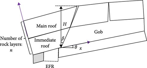
Among them, H is the roof-cutting height, h is the coal mining height, kp is the average swelling coefficient of the strata, hx is the thickness of different strata, and n is the number of strata within the roof-cutting height.
Based on the mining height of the test face and the lithologic conditions of the roof, it is concluded that the initial roof-cutting height of the test roadway is 10 m.
4.2.2. Effect of Roof-Cutting Height On Surrounding Rock Stress
We have developed a calculation model using numerical simulation software to investigate the impact of various cutting heights on the surrounding rock stress of the EFR. This model incorporates the actual geological conditions of the test site. Table 2 presents the mechanical parameters of the coal and rock mass in the numerical model [21]. Based on similarity principles, the model was configured with the following key parameters: a working face length of 260 m, a coal seam dip angle of 30°, and a coal seam thickness of 4 m. Boundary conditions were implemented with fixed horizontal displacements at both lateral boundaries and fixed vertical displacement at the base boundary.
| Rock stratum | Bulk modulus, K (GPa) |
Shear modulus, G (GPa) |
Tensile strength, T (MPa) |
Cohesion, c (MPa) |
Angle of internal friction, φ (°) |
Volumetric weight, ρ (kg/m3) |
|---|---|---|---|---|---|---|
| Overlying strata | 5.02 | 4.63 | 2.16 | 2.05 | 30 | 2320 |
| Fine sandstone | 4.78 | 3.92 | 5.54 | 3.42 | 32 | 2420 |
| Siltstone | 7.23 | 3.08 | 4.1 | 2.83 | 34 | 2150 |
| Coal seam | 3.95 | 3.22 | 0.47 | 1.20 | 29 | 1260 |
| Medium sandstone | 5.46 | 4.27 | 7.62 | 2.66 | 41 | 2370 |
We simulated and analyzed the stress distribution of the surrounding rock at cutting heights of 5, 7, 9, and 11 m. The results are presented in Figure 10.
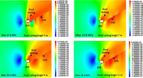
In analyzing the vertical stress distribution map of the surrounding rock shown in Figure 10, it is evident that the extent of the entry roof’s pressure relief area increases concomitantly with an increase in roof-cutting height. This observation indicates a positive correlation between roof-cutting height and the expansive influence of roof-cutting on pressure relief. Expressly, when the roof-cutting heights are set at 5, 7, 9, and 11 m, the peak stress concentrations identified within the solid coal slope are measured at 27.8, 23.8, 20.2, and 18.4 MPa, respectively. These findings indicate that roof -cutting height significantly influences the peak stress concentration within the entry’s solid coal slope, with greater cutting heights correlating to reduced peak stress concentration values. However, adopting higher cutting heights introduces complexities to on-site construction processes. Therefore, determining an optimal cutting height necessitates considering whether a rock contact surface is proximate to the designated zoning distribution. This evaluation is further informed by the outcomes of numerical simulation analyses, facilitating the adjustment and determination of specific cutting heights.
Informed by the experimental site’s engineering geological characteristics and corroborated by theoretical frameworks and numerical simulation outcomes, the cutting height for the test site is ultimately categorized into two distinct zones. Zone I, the overlying dip angle of the coal seam in this area is more than 20°, considering the gangue collapse has a particular impact on the entry gravel slope, and there is a rock interface within 1 m below the cutting datum line; the roof-cutting height was established at 9 m accordance with the selection criteria for slit height design, ensuring both adequate backfilling of the goaf and mitigation of lateral impact from collapsed rock masses on the EFR structure. Zone II, the dip angle of a coal seam in this area is less than 20°, and the baseline is located near the interface of rock formation. To ensure the filling of the caving gangue in the goaf, the cutting height was determined to be 10 m.
The test site’s roof-cutting height is ultimately categorized into two distinct zones: Zone I, 9 m and Zone II, 10 m.
4.2.3. Roof-Cutting Angle
The surrounding rock structure continues to evolve in entry stabilization due to the technological characteristics of EFR. The main roof structure of the overlying strata forms key blocks that hinge on each other, as shown in Figure 11. The roof presplitting slit angle is determined to ensure the slip between key blocks A and B, thereby cutting off the stress transfer path from the goaf to the roof of the roof-cutting area. It is essential to consider the blasting disturbance of the presplitting slit and the friction effect of the rock mass on the roof during the collapse, as these factors significantly impact the stability of the immediate roof of the entry. To mitigate the influence of these factors on the stability of the surrounding rock structure of the entry, it is generally necessary to set the slit angle θ at a certain angle to the vertical line of lead and deviate to the side of the goaf.
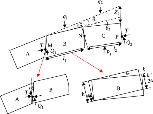
q1 and q2 represent the load on blocks B and C, respectively. θ1 and θ2 are the rotation angles of blocks B and C, while Z1 and Z2 are the sedimentation of blocks B and C. T is the horizontal thrust between key blocks, Q1 and Q2 is the hinged friction shear force between blocks. P1 is the supporting reaction force on block C, and a is the height of the contact surface. Additionally, l1 and l2 represent the length of blocks B and C, and h represents the thickness, β is the roof-cutting angle.
Because there is a hinged relationship between the key blocks, it is assumed that the contact surfaces between the two ends of the critical blocks are highly consistent. Thus, we know that the action point of the horizontal thrust between the key blocks is at a/2.
The key block’s rotary subsidence angle θ1 is related to the rock stratum stiffness. The greater the stiffness, the closer θ1 to 0. Combined with the lithology of the roof of the test entry, θ1 is 3°, φ is 26°, h is 6.8 m, the maximum rotary subsidence angle can be 3° [22], substituting these values into Equation (12) gives:
To better determine the value of roof-cutting angle, the angle is selected as 0°, 10°, 20°, and 30° for numerical simulation. The stress distribution characteristics of the surrounding rock with different roof-cutting are shown in Figure 12.
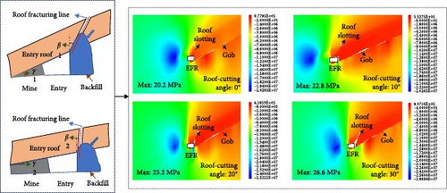
When comparing the influence of different cutting angles on the surrounding rock stress, it was observed that at 0°, the concentrated stress on the solid coal part of the EFR is 20.2 MPa; at 10°, it is 22.8 MPa; at 20°, it is 25.2 MPa; and at 30°, it is 26.6 MPa. As the cutting angle increases, the maximum stress concentration in the solid coal side also increases. This indicates that when the cutting height is determined, the deviation of the angle reduces the height of the cutting seam, affecting the extent to which the cutting seam weakens the lateral concentrated pressure. As depicted in Figure 12, if the slit angle is set to 0°, the friction resistance will lead to severe deformation of the entry roof. When the cutting seam of the roof is 30°, there is no contact between the caving gangue and the entry roof, which is not conducive to fully utilizing the supporting effect of the caving gangue. Based on theoretical analysis and numerical simulation results, different cutting angles are designed for the test entry.
In Zone I, where the inclination angle of a coal seam is more than 20°, the selection of the roof cutting angle should reduce the impact of caving in the initial stage to some extent, considering the effect of caving rock mass on the side of the goaf. The roof-cutting angle for this part is designed to be 20°. In Zone II, where the dip angle of a coal seam is less than 20°, the roof-cutting angle for this part is set at 10° to ensure the filling effect of the goaf.
4.2.4. Determination of Support Parameters of EFR in Inclined Coal Seam
To mitigate the impact of mining on the surrounding rock of EFR, we will employ a constant resistance anchor cable to reinforce the support for the entry roof before the commencement of mining activities, thereby enhancing the overall bearing capacity of the surrounding rock. Furthermore, we will implement specific support measures at various stages of the mining process to ensure the stability of the entry.
4.2.4.1. Parameters of CRLDA Cable
The prestress applied by the CRLDA cable during installation is significantly higher than that of an ordinary anchor cable, which can provide active support for the entry roof and increase its bearing capacity. The anchorage end of the constant resistance anchor cable is generally positioned 1–3 m above the height of the slit to avoid the impact of slotting blasting on the effective anchorage range. According to the suspension theory of anchor cable support, the supporting force provided by the CRLDA cable should exceed the weight of the rock mass within its supporting range. The CRLDA cable supporting structure is illustrated in Figure 13.
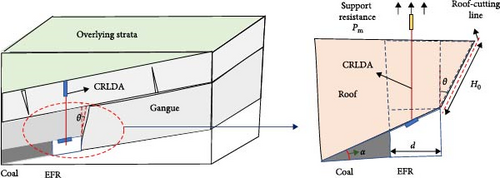
The lithology of the roof at the test site consists of siltstone interbedded with layers, having an average bulk density of 2200 kg/m3. The constant resistance anchor cable is a 21.8 mm steel strand, which provides a support resistance of 600 kN. Based on these values, the required roof support strength should meet or exceed Um ≥ 0.51 kN/m2. Consequently, the spacing of the CRLDA cables in the test entry is selected to be 2.2 m. The row distance of the constant resistance anchor cables is set at 1.0 m near the slit hole to ensure the stability of the roof, 1.5 m in the middle of the roadway, and 3.0 m on the solid coal side.
4.2.4.2. Temporary Support Parameters
A mechanical model of the EFR’s roof structure within an inclined coal seam has been developed to facilitate a comprehensive analysis of the temporary support resistance required by the support structure, as depicted in Figure 14.
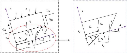
We will use a single hydraulic prop with a rated working resistance of 300 kN as a temporary support mechanism to strengthen the structural integrity of the entry support system and stabilize the adjacent rock. The architectural design of the support system consists of one beam and four columns. The distance between the single pillars next to the slit line is 800 mm, while on the opposite side, the separation between pillars is 1600 mm. The beam spacing is 1000 mm to ensure the stability in EFR constructions.
4.2.4.3. Parameters of Gangue Retaining and Supporting
The main roof undergoes rotational and vertical displacement during mining until it reaches stability. During this phase, dynamic pressure intensifies in the region proximate to the working face, particularly behind the support frame. It is imperative to implement gangue retention strategies concurrently with roof support mechanisms. This dual approach is essential to prevent gangue material’s collapse and subsequent intrusion from the mined-out area (goaf) into the entry. Furthermore, it plays a crucial role in preserving the integrity and stability of the crushed stone support infrastructure within the entry.
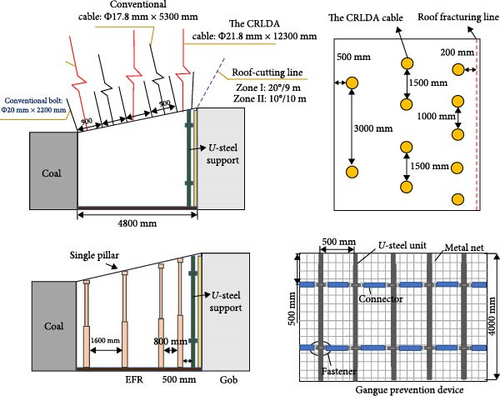
To analyze the lateral supporting force needed for the lateral gangue retaining structure, we have developed a model to calculate the lateral pressure of the EFR in inclined coal seam. In Figure 15, for ease of analysis, we assume that the gangue in the lateral slip area primarily provides the load for the gangue retaining structure. We simplify the slip area to a triangular shape DEF [24].

After considering the relevant engineering experience, the retractable U-shaped steel structure has been chosen to support gangue retention in EFR at the test site. The spacing for the U-shaped steel has been determined to be 500 mm. Summarize the analysis and calculation process. The schematic diagram illustrating the selection of key parameters for the EFR at the test site is depicted in Figure 16.
4.3. Blasting Parameters of EFR
According to the formula provided, the lithologic parameters around the slit hole and the radius of the slit hole are substituted. The diameter of the slit hole is generally 48 mm, the original rock stress P is 6.5 MPa, and μ is 0.23, Tm is 2200 MPa, D0 is 0.6, and σ0 is 4.3 MPa. This calculation results in d ≤ 547 mm, so the spacing of the slotting hole in the test entry is 500 mm.
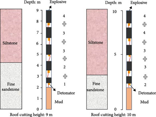
When determining the charge structure, it is essential to ensure that the charge at the edges of the hole is less than that at the center. That will help maintain the integrity around the hole after blasting and prevent damage to the surrounding support body. Additionally, the number of cartridges at the bottom of the slotted hole should be increased to compensate for the attenuation of the detonation shock wave, ensuring proper penetration at the bottom. Based on the lithologic distribution of the test site’s roof, two different charge parameter schemes are proposed for varying slit heights. The specific charge structure can be seen in Figure 17 and the final structure is determined based on field blasting tests.
5. Field Test Effect Analysis
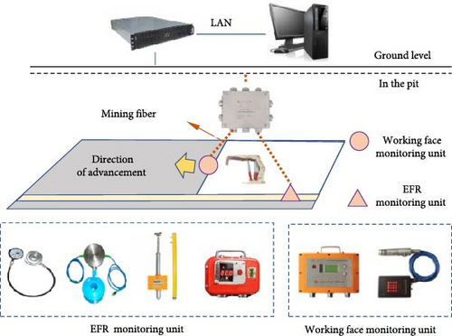
Monitoring the engineering effect of the EFR involves tracking the surface displacement of the entry and monitoring the mine pressure at the working face. The surface displacement monitoring focuses on the deformation of the surrounding rock on both sides, the roof and floor, and the separation of the entry roof in the dynamic pressure area behind working face. The primary purpose of the mining pressure analysis at the working face is to observe the support pressure and analyze the movement of the stope roof during the mining process. Observations are conducted at various locations within the test project, and relevant monitoring stations are set up, A measuring point is arranged for every five hydraulic supports in the working face. The monitoring station for the deformation and stress of the EFR’s surrounding rock is placed every 50 m with the open cut as the starting point, as depicted in Figure 18.
5.1. Analysis of Surrounding Rock Deformation Law of EFR
To scrutinize the deformation characteristics of the surrounding rock in the vicinity of a EFR, this study adopts a multifaceted approach, encompassing the analysis of data obtained from both sides of the entry, the roof-floor approaching amount, and instances of roof separation at selected monitoring stations.
As illustrated in Figure 19, the monitoring curve for the test site and the analysis of the deformation characteristics of the surrounding rock indicate that the deformation can be categorized into three stages:
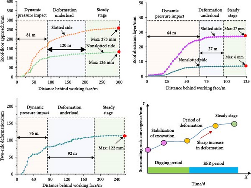
In the first stage, the dynamic pressure influence stage is the area around 0–80 m behind the working face. During this stage, the surrounding rock of the entry is affected by the immediate roof caving and the rotary subsidence of the main roof, especially in the range of 30–50 m behind the working face, indicating that the main roof of the entry is broken. The roof is subjected to incoming pressure, resulting in more significant deformation.
The second stage is the loading deformation stage, which lags behind the working face 90–200 m. In this stage, the roof of the entry is affected by the main roof rotation. The main roof is in the slow sinking stage and is in contact with the gangue in the goaf, tending to stabilize gradually.
The third stage is the stable stage of the entry, lagging 200 m behind the working face. The support system and the surrounding rock of the roadway reach a balance, which is in the stable period of roadway formation. The typical station data show that the maximum value of roof and floor approach is 273 mm, the maximum value of roof abscission layer is 27 mm, and the maximum value of two sides is 122 mm.
To sum up, the surrounding rock of the entry is not affected by the mining stress in the stage of entry driving, and the state of the surrounding rock of the entry enters stability quickly and no longer deforms. In the stage of mining, the surrounding rock is disturbed by the breaking of the overlying main roof, and the roof of the entry will produce cooperative deformation with the main roof rotation, resulting in a sharp increase in the deformation of the surrounding rock. In the end, the gangue in the goaf is compacted, and the main roof is gradually stable, the surrounding rock of the EFR tends to be stable.
5.2. Analysis of Mine Pressure
To analyze the mine pressure, we extracted the pressure data from the supports both sides of the working face for analysis. The support pressure monitoring curve is depicted in Figure 20.
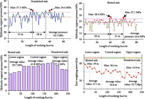
From the load distribution curve of the support strut on the slotted side and the nonslotted side in Figure 20, it can be seen that the initial weighting interval of the nonslotted side support is 33 m, the maximum load of the support is 37.3 MPa, the average pressure is 32.3 MPa, the periodic weighting step is 18 m, and the peak periodic pressure is 36.4 MPa. The initial weighting interval of the slotted side support is 39 m, the maximum load of the pillar is 28.4 MPa, the average pressure is 24.6 MPa, the periodic weighting step distance is 21 m, and the peak load of the pillar is 27.1 MPa. The initial weighting peak pressure of the lower part of the working face affected by roof-cutting is 23.9% lower than that of the non-cutting side, and the periodic peak pressure is 25.6% lower than that of the non-cutting side.
From the peak pressure and step distribution map of the support in the working face in Figure 20, it can be seen that the initial weighting strength in the middle area of the working face is more significant than that on both sides of the working face. The average value of the initial weighting in the lower area of the working face affected by roof-cutting is 29.7 MPa, the middle area is 43.8 MPa, and the upper area is 37.4 MPa. The initial weighting interval of the lower area is 39 m, 36.4 m in the middle, and 34.9 m in the upper area.
5.3. Field Application Effectiveness
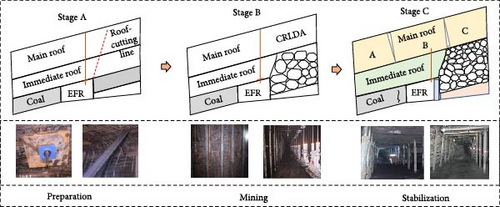
By scientifically designing key parameters for EFR and using the CRLDA we can maintain the stability of the entry roof. Combined with two-way concentrated blasting technology to control the compressive strength of the working face, and the use of a temporary support system to shape the entry, we can effectively ensure the successful implementation of EFR in the inclined coal seam. In field applications, as the working face advances, the shaping effect of the EFR is good, and the cross section after the EFR is stable can meet the production needs of the next working face. The effect of EFR in an inclined coal seam is shown in Figure 21.
6. Conclusion
- 1.
This study proposes design criteria for key parameters of EFR. By establishing a mechanical model of the surrounding rock in EFR, a theoretical calculation method for determining roof-cutting parameters in inclined coal seams was derived. Numerical simulations were conducted to validate the parameters, the following optimal values for the test mine: Zone I—roof-cutting height of 9 m with a 20° angle; Zone II—roof-cutting height of 10 m with a 10° angle.
- 2.
A mechanical model of the roof structure was developed to derive calculation formulas for key support parameters in EFR. Considering the geological conditions at the test site, the support parameters were optimized as follows: constant resistance anchor cables were spaced at 1.0 m near the slit hole, 1.5 m in the roadway center, and 3.0 m on the solid coal side. The temporary support system adopted a “one beam–four columns” configuration, with pillar spacings of 800 mm adjacent to the cutting line and 1600 mm on the opposite side. Beam spacing was maintained at 1000 mm to ensure EFR stability.
- 3.
Field monitoring data confirmed that the designed parameters effectively controlled EFR deformation and mitigated mine pressure in adjacent areas. Roof-cutting reduced the initial weighting peak pressure on the slit side by 23.9% and the periodic weighting peak pressure by 25.6% compared to the nonslit side.
- 4.
The deformation of surrounding rock in EFR can be divided into three stages: dynamic pressure influence (0–80 m behind the working face), load deformation, and stabilization. Approximately 80% of the total deformation occurred during the dynamic pressure stage.
This study investigates the selection of key parameters for EFR in inclined coal seams, focusing on mine pressure manifestation and field application through phenomenological analysis. The research acknowledges fundamental constraints: the inherent complexity of surrounding rock deformation mechanisms, overlying strata movement patterns in inclined seams, and limitations imposed by current research conditions and methodological scope. Future research should systematically examine the mechanical interactions between the surrounding rock control system and roadway deformation, integrating mine pressure theory with rock control mechanisms. Such investigations would establish a robust theoretical foundation for optimizing operational parameters in inclined seam mining environments.
Conflicts of Interest
The authors declare no conflicts of interest.
Funding
This work is supported by the National Natural Science Foundation of China (Grant 52204140), which is gratefully acknowledged.
Open Research
Data Availability Statement
The data used to support the findings of this research are included within the paper. More information can be requested from the corresponding author.


