Hierarchical Configuration of Double-Shelled Silicon Composite Anode Coated With Porous Silica and Reduced Graphene Oxide for Enhanced Li-Ion Battery Stability
Abstract
This study explores the optimization of double-shelled silicon (Si) composite anodes for lithium-ion batteries (LIBs) by examining the coating sequence of tetraethyl orthosilicate (TEOS) and reduced graphene oxide (rGO). The Si55@TEOS29@rGO16 anode, which features an inner TEOS-derived layer and outer rGO shell, exhibits an initial capacity of 1763 mAh g−1 at 0.1 C and maintains 1153 mAh g⁻1 after 300 cycles at 0.5 C, achieving a capacity retention of 85.5% when incorporating the tris(trimethylsilyl) phosphate (TMSPi) electrolyte additive. The performance improvement is attributed to the hierarchical structure, where the porous SiO2 layer effectively passivates the Si core, while the rGO shell enhances conductivity and structural stability. Comparative analysis reveals that the optimized coating sequence and TEOS content significantly enhance cycling stability, with the Si55@TEOS29@rGO16 anode surpassing other configurations in specific capacity after 129 cycles. Scanning electron microscopy (SEM) and transmission electron microscopy (TEM) analyses confirm the uniform coating and structure stability after cycling. Electrochemical impedance spectroscopy (EIS) shows reduced impedance, and cyclic voltammetry (CV) indicates stable lithiation/delithiation processes. The inclusion of the TMSPi additive further stabilizes the solid electrolyte interphase (SEI) and inhibits capacity fading during initial cycles. This study demonstrates that optimizing the coating sequence, SiO2 content, and electrolyte additives can significantly improve the electrochemical performance and durability of Si-based anodes, positioning them as strong candidates for next-generation LIBs.
1. Introduction
The rapid advancement of portable electronics, electric vehicles, and renewable energy storage systems has significantly increased the demand for lithium-ion batteries (LIBs) with higher energy density, longer lifespan, and enhanced safety. Silicon (Si) anodes have gained considerable attention due to their exceptionally high theoretical capacity (~4200 mAh g−1), nearly 10 times greater than conventional graphite anodes (~372 mAh g−1) [1]. However, the practical application of Si in LIBs is severely hindered by its substantial volume expansion during lithiation, which can reach over 300% [1]. This expansion leads to the pulverization of the Si particles, the breakdown of the electrode structure, and rapid capacity degradation [1]. Therefore, developing strategies to mitigate these challenges is crucial for the advancement of Si-based anodes.
To address the issue of swelling and shrinkage of Si during lithiation and delithiation, previous studies have investigated the use of various coating materials or composite designs [2–5]. Reduced graphene oxide (rGO) has emerged as a promising candidate due to its flexibility, high electrical conductivity, and its ability to create a stable surface for solid electrolyte interphase (SEI) formation [6, 7]. This conductive carbon layer not only accommodates the strain induced by Si expansion but also improves the overall conductivity of the anode. On the other hand, silica (SiO2) coatings have been employed for their ability to passivate the active Si surface, thereby reducing its tendency to swell and forming stable SEI [8, 9]. SiO2 also offers significant mechanical strength, helping to maintain the structural integrity of the anode. Moreover, SiO2 can serve as a precursor to the formation of SEI containing lithium silicates, which are stable and provides good ionic conductivity, further enhancing the electrochemical performance of the anode [10, 11]. Despite the significant advancements in individual use of these materials, systematic investigations into the optimal sequential configuration of multilayer coatings (e.g., combining rGO and SiO2) remain limited.
This research focuses on a comparative study of the coating sequences of tetraethyl orthosilicate (TEOS), a precursor to silica, and rGO in the construction of a double-shelled Si composite anode [12]. The aim is to determine which coating sequence—rGO followed by TEOS or TEOS followed by rGO—is more effective in mitigating volume expansion of active Si and improving the overall electrochemical performance of the anode. Additionally, this study explores optimizations in the coating ratio and the incorporation of an electrolyte additive to further enhance the performance of the Si composite anode. Moreover, this study provides critical understanding of the interplay between structural configurations and electrochemical behavior, shedding light on how hierarchical double-shelled designs mitigate capacity fading and enhance stability. By systematically investigating these variables, this work seeks to contribute valuable insights into the design of more durable and efficient Si-based anodes for next-generation LIBs.
2. Experimental
2.1. Synthesis of Double-Shelled Si Composite Materials
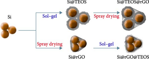
The double-shelled Si composite materials were synthesized using a modified Stöber sol–gel method [13], incorporating cetyltrimethylammonium bromide (CTAB) to improve the porosity of the resulting SiO2 shells [14]. Initially, Si powder, CTAB, ethanol, and deionized water were mixed and dispersed using a probe sonicator for 30 min. To this mixture, ammonia solution (NH4OH) and TEOS were sequentially added, followed by continuous stirring at 30°C for 12 h to facilitate the hydrolysis of TEOS, forming a porous SiO2 shell around the Si particles. The resulting mixture was filtered and washed with deionized water until the filtrate reached a neutral pH. The collected powder was dried at 80°C in a circulating oven. The dried powder was then subjected to thermal treatment in an argon (Ar) atmosphere, heated at a rate of 10°C/min to 800°C, and held for 2 h to remove CTAB, yielding a porous SiO2 shell around the Si core (denoted as Si@TEOS). Subsequently, the Si@TEOS powder was mixed with graphene oxide (GO) dispersion, single-walled carbon nanotubes (SWCNTs), and deionized water, followed by sonication for 30 min. A polyvinyl alcohol (PVA) solution was added to the mixture and stirred for 12 h. The homogenized Si@TEOS@GO mixture was then spray-dried at 300°C to form granules. The spray-dried powder was further heated at 950°C for 1 h in an Ar atmosphere, reducing GO to rGO and forming the final Si@TEOS@rGO double-shelled Si composite. The weight ratios of the components, based on the added TEOS, Si, and GO, were denoted as Sixx@TEOSyy@rGOzz. A reverse order of coating, resulting in Si@rGO@TEOS, was also prepared to compare the effects of hierarchical structural variations on battery performance, as shown in Figure 1.
2.2. Electrode Preparation and Cell Assembly
The anode slurry was composed of the active material (Si@TEOS@rGO or Si@rGO@TEOS), conductive agents (Super P and SWCNT), and binders (carboxymethyl cellulose [CMC] and styrene-butadiene rubber [SBR]). The weight ratio of the components was maintained as active material: super P:CMC:SBR:SWCNT = 70:10:10:10:0.5. Initially, SWCNT was dispersed in deionized water using a probe sonicator for 30 min, followed by the addition of CMC, which was stirred for another 30 min. Super P was then added and stirred for 1 h, followed by the active material with a stirring time of 3 h. Finally, SBR was added and stirred for 15 min. The resulting slurry was uniformly coated onto copper foil and dried in a vacuum oven at 80°C. The electrodes were then punched into 1.5-cm-diameter discs. For cell assembly, CR2032 coin cells were constructed in an Ar-filled glovebox (MBraun) with extremely low levels of moisture and oxygen. The cells consisted of the prepared anode, a lithium metal counter electrode, a Celgard separator, and an electrolyte composed of 1 M LiPF6 in a 1:2 volume ratio of ethylene carbonate (EC) to ethyl methyl carbonate (EMC), with an additional 25 vol % fluoroethylene carbonate (FEC).
2.3. Electrochemical Characterizations
Battery cycling performance was evaluated using a programmable battery cycler (Lanhe CT3002A). The current rate of 1 C was defined as 2000 mAh g−1. After a 12-h rest period following cell assembly, the cells were cycled between 0.01 and 1.5 V at 0.1 C for the first three cycles, followed by subsequent cycles at 0.5 C. Cyclic voltammetry (CV) and electrochemical impedance spectroscopy (EIS) were performed using PalmSens EmStat4S and BioLogic SP-50e potentiostats, respectively. CV measurements were conducted between 0.01 and 1.5 V at a scan rate of 0.1 mV s−1. EIS data were collected over a frequency range of 1 MHz to 10 mHz with an AC voltage amplitude of 10 mV. Li-ion diffusivity was evaluated using the galvanostatic intermittent titration technique (GITT) [15]. A 0.1 C current pulse was applied during charging until the voltage reached 1.5 V and during discharging until it dropped to 0.01 V, with each pulse followed by a 10-min relaxation period to ensure equilibrium.
2.4. Material Characterizations
The microstructure of the synthesized materials was analyzed using scanning electron microscopy (SEM; Hitachi SU-8010) and transmission electron microscopy (TEM; JEOL JEM-2100F). Energy-dispersive X-ray spectroscopy (EDX) integrated with TEM provided elemental mapping and detailed analysis of elemental distributions and material morphology. X-ray diffraction (XRD; Bruker D2 phaser) using Cu Kα radiation was performed over a 2θ range of 10° to 80° to assess crystallographic properties. Fourier transform infrared (FTIR) spectra were recorded with a FTIR spectrometer (Bruker Vertex 80v/Tensor 27). The surface area and pore size distribution were analyzed using the Brunauer–Emmett–Teller (BET) method and the Barrett–Joyner–Halenda (BJH) model with nitrogen adsorption (Micromeritics ASAP 2020). X-ray photoelectron spectroscopy (XPS; ULVAC-PHI Quantera II) with depth profiling, facilitated by an Ar ion gun (1 kV), was employed to determine the composition of the composite anodes at various depths. The Ar+ beam was used to reveal underlying compositional changes by gradually removing material layer by layer, with etching intervals performed at a sputtering rate of 15.9 nm min−1 calibrated using a SiO2 standard.
3. Results and Discussion
Figure 2a illustrates the cycling performance of pristine Si, Si55@rGO16@TEOS29, and Si55@TEOS29@rGO16 composite anodes, highlighting significant differences in specific capacity and Coulombic efficiency over 300 cycles. The uncoated pristine Si anode exhibits rapid capacity decay, dropping from 2967 mAh g−1 in the first cycle (0.1 C) to a mere 17.6 mAh g−1 by the 300th cycle (0.5 C). The Si55@rGO16@TEOS29 anode, featuring an inner rGO coating and outer TEOS-derived layer, shows improved stability, with an initial capacity of 2263 mAh g−1 (0.1 C) that declines to 697 mAh g−1 after 300 cycles (0.5 C). In contrast, the Si55@TEOS29@rGO16 anode, which has TEOS coated inside and rGO outside, demonstrates superior long-term stability, albeit with a lower initial capacity of 1505 mAh g−1 (0.1 C). This anode maintains 971 mAh g−1 after 300 cycles (0.5 C) and surpasses the Si55@rGO16@TEOS29 in specific capacity after the 129th cycle. The low capacity contribution from porous SiO2 generated by the TEOS coating (<100 mAh g−1; Figure S1a) means that the majority of the capacity is still provided by the active Si. As shown in Figure 2b, the Si55@TEOS29@rGO16 anode exhibits a higher capacity retention rate just after 50 cycles compared to the other configurations, demonstrating a more stable performance. Without the conductive rGO layer, the insulating and porous TEOS-derived surface coating fails to facilitate Si utilization and stable SEI formation, resulting in poor capacity retention and cycle life (Figure S1b). The noticeable capacity fluctuation and higher initial capacity retention observed for Si55@rGO16@TEOS29 can be attributed to the outer TEOS-derived SiO2 layer promoting a thorough initial redox reaction of SiO2, contributing additional reversible capacity. Moreover, the conductive rGO directly in contact with the unpassivated inner Si core significantly enhances the initial utilization of active Si, resulting in temporarily elevated capacities during early cycling, though stability deteriorates rapidly thereafter. These results highlight the importance of hierarchical structural design in enhancing the cycle stability of Si composite anodes for LIBs, with the Si@TEOS@rGO configuration emerging as a more effective approach.
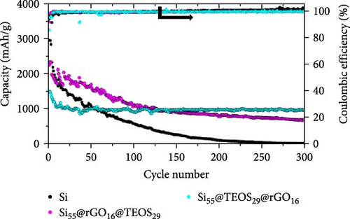
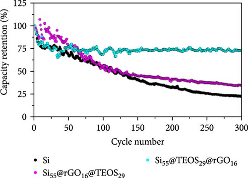
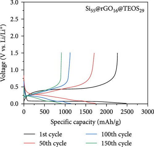
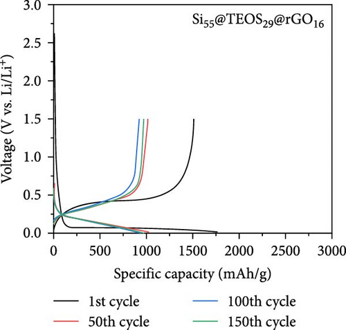
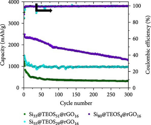
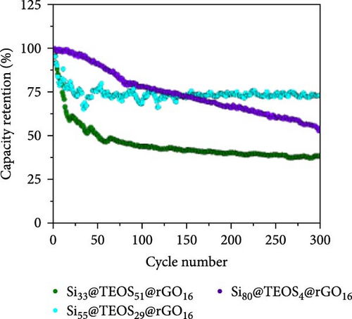
Figure 2c,d presents the typical charge and discharge curves of Si-based anodes, showing a low lithiation voltage below 0.1 V during the first cycle and a delithiation plateau at less than 0.5 V. As cycling progresses, the second discharge plateau becomes sloped due to the transformation of crystalline Si into amorphous Si [6, 16]. Although the Si55@rGO16@TEOS29 anode exhibits a higher initial discharge capacity than Si55@TEOS29@rGO16, by the 150th cycle, Si55@TEOS29@rGO16 surpasses Si55@rGO16@TEOS29 in reversible capacity, indicating its superior long-term cycling performance. Therefore, the Si@TEOS@rGO structure was chosen as the main focus for optimization and analysis in this study. By varying the amount of TEOS added, the content of porous SiO2 coating on Si was adjusted to optimize the cycling performance. The study compares electrodes with three different weight ratios: Si:TEOS:rGO (33:51:16), Si:TEOS:rGO (55:29:16), and Si:TEOS:rGO (80:4:16), labeled as Si33@TEOS51@rGO16, Si55@TEOS29@rGO16, and Si80@TEOS4@rGO16, respectively. As shown in Figures 2e and S2a, the Si33@TEOS51@rGO16 electrode has the lowest initial capacity of 1215 mAh g−1 at 0.1 C, dropping to 326 mAh g−1 at 0.5 C after 300 cycles, with a poor capacity retention rate of 38.9% (Figure 2f). This suggests that while a higher TEOS content provides a thicker SiO2 protective layer, it also reduces electrical and ionic conductivity. Conversely, the Si80@TEOS4@rGO16 electrode shows the highest initial capacity at 2376 mAh g−1 at 0.1 C (Figure S2b), but its capacity declines significantly to 1282 mAh g−1 at 0.5 C after 300 cycles (Figure 2e), with a huge decay rate of 46.7% (Figure 2f). This indicates that insufficient TEOS content fails to provide adequate protection, leading to poorer cycling performance. The Si55@TEOS29@rGO16 electrode, however, exhibits the best overall performance, with the highest capacity retention rate of 73.4% at 0.5 C after 300 cycles. As seen in Figure 2f, its capacity retention surpasses that of Si80@TEOS4@rGO16 after 145 cycles, demonstrating that a TEOS content of 29% is optimal for this composite structure.
Figures 3a–c and S3a–S3b illustrate the CV curves for Si55@TEOS29, Si55@rGO16@TEOS29, Si55@TEOS29@rGO16, Si33@TEOS51@rGO16, and Si80@TEOS4@rGO16 composite anodes. In the first discharge stage, all five materials exhibit a broad peak around 0.8 V, indicating the electrolyte decomposition and the SEI formation on the electrode surface [6]. This voltage also corresponds to the irreversible lithiation of porous SiO2 coating generated by the TEOS, as shown in Figure S1a. These irreversible reactions consume a significant amount of Li+ ions, and the peak disappears in subsequent cycles [17]. The signal from rGO is not clearly observed, likely due to its low loading and relatively low capacity. The LixSi alloying reaction during the first cycle occurs close to 0 V, while in later cycles, a peak appears between 0.19 and 0.2 V during discharge, signaling the formation of the LixSi alloy from amorphous Si [6, 16, 18]. During the charging process, peaks are observed between 0.35 and 0.37 V and 0.49 and 0.50 V, corresponding to the delithiation of the LixSi alloy [17–21]. Starting from the second cycle, the peak positions stabilize, demonstrating the high reversibility of the lithiation and delithiation processes [22]. With continued cycling, the peak current increases as Si activity enhances due to repeated lithiation (expansion) and delithiation (shrinkage), which continuously activates the Si structure, exposing fresh active surfaces [23, 24]. Therefore, protecting the internal Si from expansion and rupture during charge–discharge cycles is crucial for extending the cycle life of LIBs.

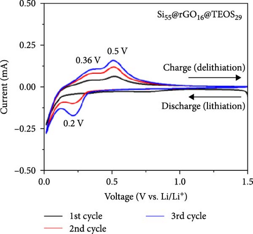
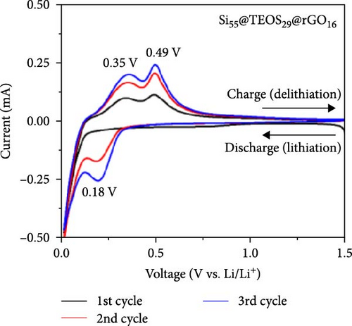
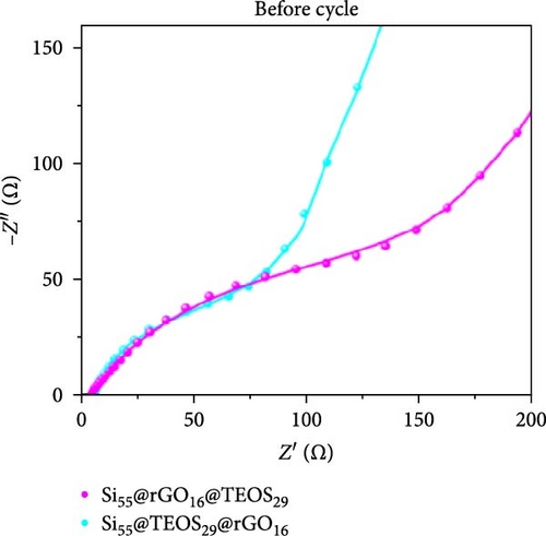
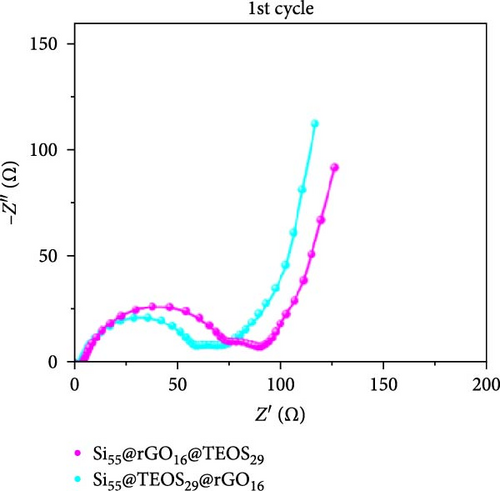
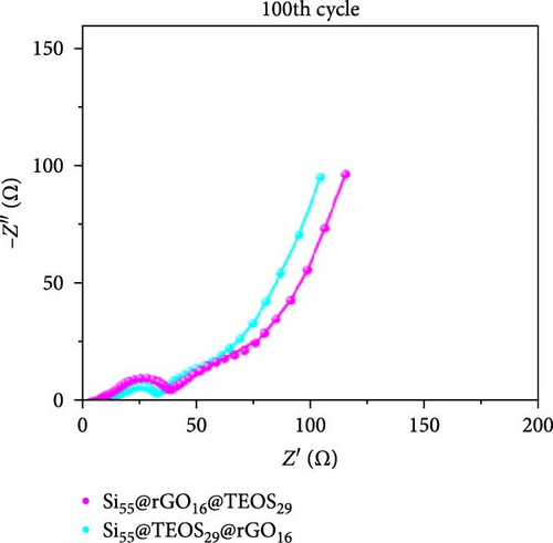
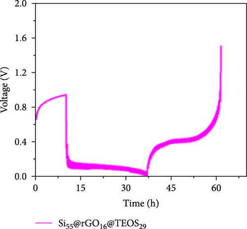
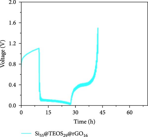
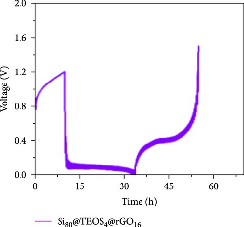
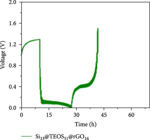
Figure 3d–f shows the EIS of Si55@rGO16@TEOS29 and Si55@TEOS29@rGO16 composite electrodes before cycling, after the first cycle, and after the 100th cycle. The uncycled fresh electrodes exhibit large semicircles, indicating high impedance due to the absence of SEI formation and unreacted insulating SiO2. This results in poor conductivity for both electrons and Li+ ions [25]. The Si55@rGO16@TEOS29 electrode, with its outer SiO2 coating, faces poor electrical conductivity, impeding electron transport between particles and consequently resulting in higher impedance. In contrast, Si55@TEOS29@rGO16, which has porous SiO2 coated on the inner layer and rGO on the outer layer, avoids these issues by maintaining lower interparticle contact resistance and ensuring smoother Li+ ion transport. The graphite-like outer rGO layer on Si55@TEOS29@rGO16 not only enhances conductivity but also stabilizes SEI growth and prevents direct reactions between SiO2 and the electrolyte [26]. This stable multilayer SEI, formed by lithium silicates under the protection of rGO and organic/inorganic SEI compounds, provides a consistent Li+ ion diffusion channel, contributing to uniform electrochemical reactions and stable impedance values over time [27]. Conversely, when porous SiO2 is on the outer layer (Si@rGO@TEOS), the brittle lithium silicate may delaminate from the flexible rGO layer due to repeated volume expansion during cycling, compromising long-term stability. These results align with previous cycle life comparisons, confirming that the Si@TEOS@rGO structure is ideal for achieving long cycle life in LIBs. The GITT technique was employed to investigate the Li-ion diffusion process in the electrodes, involving a cycle of pulse-current and relaxation phases [15]. During each cycle, a constant current of 0.1 C was applied for 10 min for charging or discharging, followed by a 10-min relaxation period with no current [15]. Voltage changes during both the constant current and relaxation phases were recorded to calculate the diffusion coefficients. Comparisons of the GITT results for the Si composite electrodes are presented in Figure 3g–j and Table S1. The Si55@rGO16@TEOS29 composite anode exhibits the highest diffusion coefficient, indicating an open structure that facilitates Li+ ion transport and contributes to its high capacity. However, higher capacity is often accompanied by poor expansion control, potentially affecting cycle life. In the Si@TEOS@rGO configuration, similar diffusion coefficients are observed at the start of delithiation. Toward the end of the cycle, the Si33@TEOS51@rGO16 anode, with its thicker coating, shows the lowest diffusion coefficient due to the overly thick passivation layer. These findings highlight the importance of optimizing the structural content to balance electrode stability and electrochemical performance.
To analyze the microstructure of the double-shelled Si composite material, SEM analysis was employed. The surface of pure Si (Figure 4a), with particle sizes ranging from tens to hundreds of nanometers, reveals irregular, island-like morphology with slightly rough surfaces, which provide anchor points for subsequent coatings. The SiO2 generated by the sol–gel method using TEOS (Figure 4b) exhibits a porous surface morphology, with CTAB acting as a template agent that forms a microemulsion in the solution [28]. This self-assembles into a regular porous structure, guiding the deposition of SiO2 and creating diffusion paths for Li+ ions. The SEM image of the Si@TEOS composite (Figure 4c) shows a smoother and more rounded surface compared to pure Si, forming a continuous SiO2 coating. Figure 4d presents the Si55@rGO16@TEOS29 structure, where the outer layer is coated with porous, rough SiO2 [28 ]. The thicker SiO2 shell, being less conductive than rGO, clearly appears as the outermost layer, concealing the core Si particles. Figures 4e and S4a,b display the structures of Si55@TEOS29@rGO16, Si33@TEOS51@rGO16, and Si80@TEOS4@rGO16, respectively, where the outer layer of the particle has a complete rGO coating with a crumpled tissue paper-like texture, due to the spray drying method used. The underlying Si@TEOS structure is visible beneath the translucent rGO layer, indicating that the core–shell structure has been successfully coated with rGO, forming a well-integrated composite material.
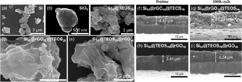
Comparing SEM cross-sections of electrodes before and after cycling provides insights into the expansion rate and morphological changes that occur after multiple charge and discharge cycles. Figure 4f illustrates the electrode structure of Si55@rGO16@TEOS29, which features an outer TEOS-derived coating. After 100 cycles, the expansion rate reached 261%, and numerous cracks appeared in the electrode structure due to severe swelling (Figure 4g). In contrast, the Si55@TEOS29@rGO16 structure, which has TEOS-derived coating on the inner layer (Figure 4h), exhibited a significantly lower expansion rate of 63.8% after 100 cycles, maintaining good electrode density (Figure 4i). This indicates that this structural configuration effectively suppresses undesired electrode expansion. Further comparison of electrodes with different TEOS ratios revealed varying expansion behaviors. Figure S5a–d shows the expansion rates of two other electrodes before and after cycling: Si33@TEOS51@rGO16 had an expansion rate of 124%, while Si80@TEOS4@rGO16 experienced a much higher expansion rate of 531%. Among the tested structures, Si55@TEOS29@rGO16 demonstrated the most favorable expansion suppression and structural integrity, highlighting its optimized design for better cycle stability.
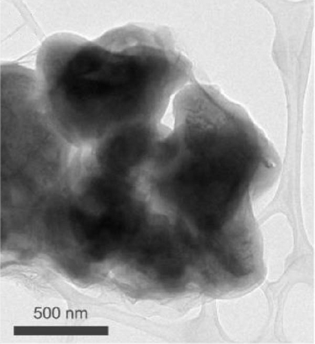
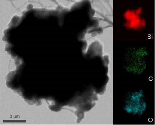
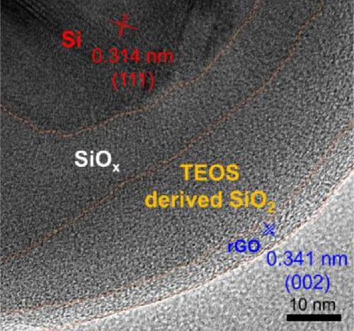
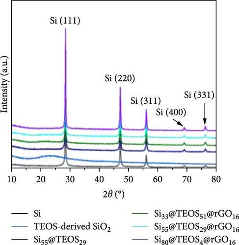
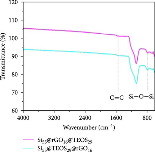
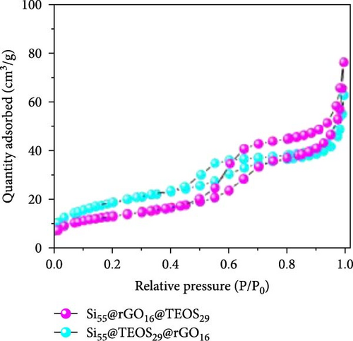
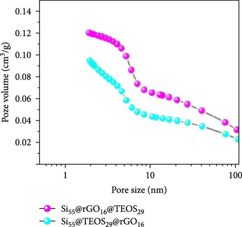
After determining that the optimal structure and TEOS ratio of the double-shelled Si composite material, we conducted further analysis using TEM imaging, high-resolution TEM (HRTEM), and EDX elemental mapping to gain a deeper understanding of the hierarchical composite microstructure. The TEM image of the Si55@TEOS29@rGO16 composite material (Figure 5a) reveals that, similar to the SEM results, the Si particles are encapsulated by an inner layer of SiO2 formed from TEOS, and this is further enclosed by an outer rGO layer. The EDX mapping of Si55@TEOS29@rGO16 (Figure 5b) shows the distribution of Si, C, and O elements, confirming that each shell layer in the composite material fully encapsulates the Si particles. The HRTEM image of Si55@TEOS29@rGO16 (Figure 5c) provides a clearer view of the multilayered coating structure. As depicted, the innermost layer is pure Si, the primary active material of the anode, with an interplanar spacing of 0.314 nm corresponding to the (111) Si crystal plane [6, 22]. In this experiment, no special treatment was applied to remove the native oxide layer from the Si material, so a natural amorphous SiOx oxide layer is present on the surface of the Si particles [6]. Moving outward, the artificial SiO2 layer, which was coated using the TEOS reaction, can be observed, showing the growth of SiO2 from TEOS. Finally, the outermost layer consists of rGO, which is well-coated around the SiO2 shell. The interplanar spacing of 0.341 nm corresponds to the (002) graphite crystal plane [6]. Figure 5d presents the XRD patterns of various samples, including Si, SiO2 (synthesized from TEOS), Si55@TEOS29, Si33@TEOS51@rGO16, Si55@TEOS29@rGO16, and Si80@TEOS4@rGO16. The composite materials containing pure Si display characteristic peaks at 28.4°, 47.3°, 56.1°, 69.1°, and 76.3°, corresponding to the (111), (220), (311), (400), and (331) crystal planes of Si, respectively (JCPDS card no. 27-1402) [6, 16]. Additionally, a broad peak at around 23° is observed, corresponding to SiO2 and reflecting its amorphous nature [12]. Notably, all Si-containing composites exhibit strong diffraction signals from pure Si particles, indicating that the porous SiO2 film derived from TEOS/CTAB is sufficiently thin, which is beneficial as it enhances the ionic and electronic conductivity of the composite, contributing to the overall performance of the double-shelled Si composite material. FTIR analysis (Figure 5e) confirms the presence of SiO2 through distinct Si–O–Si peaks in both Si55@TEOS29@rGO16 and Si55@rGO16@TEOS29 materials, indicating the successful transformation of TEOS into solid-phase SiO2 [29 ]. BET and BJH analyses (Figure 5f,g) reveal that Si55@TEOS29@rGO16 exhibits a slightly higher surface area (65.8 m2/g) compared to Si55@rGO16@TEOS29 (46.1 m2/g), while the pore volume shows the opposite trend (0.097 vs. 0.12 cm3/g). These results indicate that the external rGO layer provides higher surface area, while the external TEOS-derived coating offers higher pore volume.
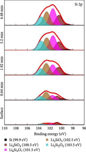
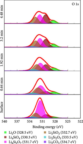
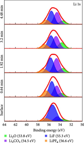
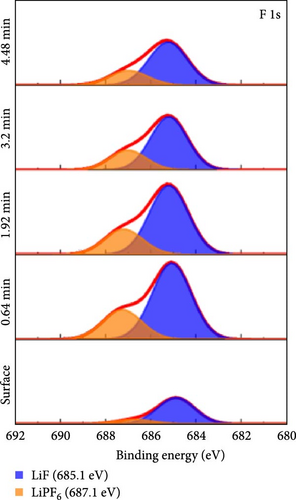
To investigate the chemical composition of lithium silicates derived from lithiated SiO2 on the composite electrode surface, XPS depth profiling analysis was conducted. Figure 6 provides a detailed compositional analysis of the various elements present in the Si55@TEOS29@rGO16 electrode after 100 cycles. The Si 2p (Figure 6a) and O 1s (Figure 6b) spectra reveal the presence of multiple lithium silicate phases with varying Li/Si ratios, including Li4SiO4, Li6Si2O7, Li2SiO3, and Li2Si2O5 [10, 11]. This indicates that in the Si@TEOS@rGO structural design, Li+ ions interact not only with the pure Si core but also with the SiO2 inner shell, leading to the formation of an inorganic SEI layer composed of lithium silicates. These lithium silicate phases are uniformly distributed across different electrode depths, with a slightly higher proportion of high Li/Si ratio phases (Li4SiO4 and Li6Si2O7) compared to low Li/Si ratio phases (Li2Si2O5). Previous literature indicates that the lithium silicate phases with a high Li/Si ratio, once formed through reactions with Li+ ions, tend to be highly irreversible and remain within the electrode structure [10, 30, 31]. Additionally, common inorganic SEI phases such as Li2O, Li2CO3, and LiF are clearly visible in the O 1s (Figure 6b), Li 1s (Figure 6c), and F 1s (Figure 6d) spectra, along with residual traces of the electrolyte salt LiPF6. As the etching depth increases, the peak intensity of Li2O gradually rises, indicating that the fast ion channel provided by Li2O tends to emerge at the SiO2–Si interface, thus offering an excellent ion-conducting layer at this boundary [32]. The inclusion of FEC additives in the electrolyte is crucial for the cycling performance of the electrode, as LiF formation plays a significant role that exhibits excellent mechanical properties, which effectively suppress the stress caused by the continuous expansion and contraction of the Si-based anode, thereby extending the cycle life [19, 33]. The presence of these inorganic SEI components helps to stabilize the interface between the electrolyte and the electrode, ensuring efficient Li+ ion insertion and extraction during electrochemical reactions. Lithium silicates, in particular, provide excellent mechanical and thermodynamic stability and Li+ ion conductivity, effectively limiting the expansion of Si materials and improving Li+ ion diffusion.
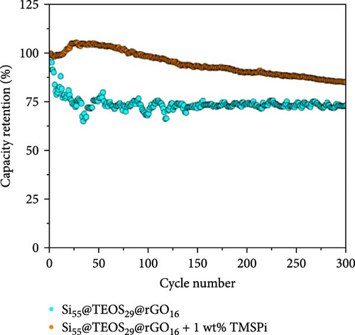
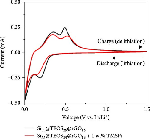
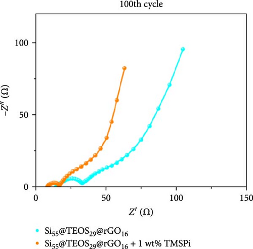
To further enhance the cycling performance of the double-shelled Si composite anode, a novel tris(trimethylsilyl) phosphate (TMSPi) electrolyte additive was utilized in this study. This additive not only neutralizes the strong acid HF generated by the electrolyte and trace water molecules during cycling but also forms an initial SEI containing unique P−O−Si-based compounds [34, 35]. These compounds help maintain interfacial stability and prevent excessive SEI reformation during prolonged cycling [35]. In the cycle life comparison, the addition of TMSPi significantly improved performance, with the capacity remaining at 1153 mAh g−1 after 300 cycles. This is markedly higher than the capacity observed in the electrolyte without additives (Figure 7a). The capacity retention rate also increased from 73.4% to 85.5% (Figure 7b), with a noticeable suppression of capacity fading during the first 30 cycles. This initial period typically involves repeated SEI formation and the pulverization of Si material. The results demonstrate that TMSPi effectively stabilizes the electrochemical reactions of Si-based anode during early cycling. Furthermore, with the addition of TMSPi, the CV delithiation peak at 0.52 V is significantly lower and broader than the peak at 0.34 V (Figure 7c), as well as than the peak in the baseline electrolyte. This indicates that TMSPi effectively inhibits the formation of the c-Li3.75Si phase, which is known to compromise the Si structure and cause severe pulverization of active Si [36]. This inhibition explains the superior cycle life observed with the use of TMSPi. Due to excellent SEI film-forming properties and HF scavenging characteristics of TMSPi [35], it significantly reduces the impedance value of the double-shelled Si composite anode after 100 cycles, as shown in Figure 7d, resulting in outstanding capacity retention over extended cycling. Table S2 provides a summary of Si/SiO2 composite anodes for LIBs from prior studies. Several approaches, such as the Mg reduction of SiO2 to produce Si, often involve expensive or complex processes, limiting their scalability. In contrast, our composite anode employs the Stöber sol–gel method with a CTAB template, facilitating the formation of a porous SiO2 coating that ensures smooth Li+ ion diffusion. This is complemented by the thermally reduced rGO layer, which provides high mechanical strength and excellent capacity retention over cycling. Additionally, the inclusion of the advanced electrolyte additive TMSPi enhances interfacial stability, further improving cyclability.

4. Conclusions
The study presents a comprehensive analysis of Si-based composite anodes with a double-shelled structure, focusing on the impact of various structural configurations and the TMSPi electrolyte additive on their electrochemical performance. Initially, the cycling performance of pristine Si, Si55@rGO16@TEOS29, and Si55@TEOS29@rGO16 composite anodes was compared. The results indicated that while the pristine Si anode exhibited rapid capacity decay, the composite anodes with hierarchical coatings significantly improved stability. Among them, the Si55@TEOS29@rGO16 anode, featuring a TEOS inner coating and an rGO outer layer, demonstrated superior long-term cycling performance, maintaining a higher capacity retention rate over 300 cycles. The effectiveness of this configuration is attributed to the structural protection offered by the inner SiO2 layer and the enhanced conductivity provided by the outer rGO layer. Further optimization of the TEOS content in the composite anodes revealed that a 29% TEOS ratio yielded the best performance, balancing the protective properties of SiO2 with the need for sufficient ionic and electronic conductivity. This optimized structure minimized capacity fading and exhibited the lowest expansion rate during cycling, indicating excellent structural integrity and stability. Electrochemical and chemical analyses, including CV, EIS, and XPS, confirmed the formation of a stable SEI layer, predominantly composed of lithium silicates and other inorganic compounds, which further contributed to the enhanced cycle life by maintaining interfacial stability and efficient Li+ ion transport. The incorporation of a TMSPi electrolyte additive further improved the cycling performance by reducing impedance and stabilizing the SEI layer. This additive worked synergistically with the hierarchical double-shelled structure, enhancing the anode’s overall durability and long-term stability. Notably, the study highlights that the strategic combination of a TEOS-derived porous inner layer and an rGO outer shell significantly mitigates the challenges associated with Si anode swelling and capacity fading, addressing one of the critical barriers in LIB development. Overall, the study highlights the critical role of hierarchical structural design and optimized electrolyte systems in enhancing the cycle stability and performance of Si composite anodes for LIBs. The Si55@TEOS29@rGO16 structure, in particular, stands out as a highly effective configuration, offering a promising pathway for the development of high-performance and long-lasting anodes in next-generation energy storage systems.
Conflicts of Interest
The authors declare no conflicts of interest.
Author Contributions
Chun-Wei Huang: writing–original draft, visualization, validation, investigation, formal analysis, data curation. Thao Nguyen: validation, investigation, formal analysis, data curation. Yi-Chuan Chu: formal analysis, data curation. Jeng-Kuei Chang: writing–review and editing, resources, formal analysis. Pai-Yen Chen: writing–review and editing, validation, formal analysis. Yu-Sheng Su: writing–review and editing, writing–original draft, validation, methodology, supervision, resources, project administration, methodology, investigation, funding acquisition, conceptualization.
Funding
This research was funded by the National Science and Technology Council (NSTC) of Taiwan (113-2628-E-A49-011) and the Ministry of Education (MOE) of Taiwan under the Yushan Young Fellow Program and Higher Education SPROUT Project of National Yang Ming Chiao Tung University.
Supporting Information
Additional supporting information can be found online in the Supporting Information section.
Open Research
Data Availability Statement
Data are available on request from the authors.


