Enhanced Cycling Performance of Electrospun Nickel Cobalt Manganese Oxide [LiNi0.8Co0.1Mn0.1O2(NCM811)] Cathode for Lithium-Ion Batteries
Abstract
The cathode of a lithium-ion battery (LIB) is made from a slurry of cathode active materials, conductive additives, and binder mixtures, which is blade-coated to fabricate the cathode electrode. The blade coating is a wet coating technology, which requires a heat treatment process after casting to volatilize the solvent. In addition, due to the dense surface, the reaction occurs mainly on the surface during the charge and discharge cycle, which accelerates degradation. To address these problems, this study introduces electrospun coatings during slurry casting. Electrospinning (ES) is a fast, easy, and low-cost process that is not limited by external conditions and is typically used to produce nanofibers. However, if the polymer solution concentration is extremely low, a porous film can be formed by electrospraying. Porous films tend to degrade more slowly because the reaction occurs across the entire electrode. In addition, ES does not require a drying process as the solvent is volatilized during the process. While the blade coating shows 47.13% retention after 100 cycles at 1C, ES shows an improved retention of 75.98%. The application of ES to LIB results in a significant improvement in cycle performance, which can be developed into a breakthrough technology in electrode fabrication.
1. Introduction
Lithium-ion battery (LIB) performance enhancement technologies have become increasingly important in recent years, with the advances in electric vehicles (EVs) and electronic devices such as personal cell phones, laptops, and electric bicycles [1, 2]. LIBs are suitable for high current loads and have the advantages of high capacity, long life, no memory effect such as battery capacity degradation during charging and discharging, and a very low self-discharge rate even after charging [3, 4]. It also has the advantage of allowing flexibility in battery shape (despite the popularity of certain shapes), due to the ease of design changes, such as can or pouch forms [5].
The LIB consists of three main components: the anode, cathode, and separator. The cathode plays a critical role in the performance of the battery, including its energy density, output, lifetime, and even price [6, 7]. Cathode materials include lithium cobalt oxide (LCO), lithium iron phosphate (LFP), lithium manganese oxide (LMO), nickel cobalt manganese (NCM), and nickel cobalt aluminum (NCA), among which especially NCM cathodes are attracting attention [2, 8–10]. Compared to other cathode materials, NCM cathodes have superior energy density, stability, and cost-effectiveness. Although the capacity varies depending on the nickel content, NCM cathodes combine the advantages of both LCO and LMO, with high capacities of 200–210 mA h/g at a cutoff voltage of 3.0−4.3 V and excellent cycling performance. For these reasons, NCM cathodes have been the focus of much research and development [11].
The typical cathode of a LIB consists of a cathode active material, binder, and conductive additive. The role of the cathode is to store and release energy by providing the necessary electrochemical reactions for charging and discharging process [6]. The selection and design of the cathode material are very important because the performance of the cathode directly affects the overall performance of the battery. Typically, these cathodes are made by a mixture of cathode active materials, binders and conductive additives in the proper proportions dissolved in a suitable solvent to form a cathode slurry, which is then coated onto aluminum foil [12]. The slurry is coated by slot-die coaters, comma coaters, and blade coaters. In a conventional laboratory, electrodes are typically cast through a blade coater [13]
However, the blade coating (bar coating) technology for electrodes faces several challenges. For example, the lack of lithium-ion active area due to the flat surface and the heavy edge phenomenon [13, 14] due to the wet process. More importantly, it is difficult to reduce the cost of batteries due to the complexity of multiple processes, such as process line equipment for blade coating in the electrode process and heat treatment equipment to evaporate solvents, etc. (Figure 1). These issues are significant factors limiting battery performance and lifespan, and they also contribute greatly to the challenge of reducing battery costs.

One innovative approach to addressing these issues is electrospinning (ES). ES is the technique of applying a high voltage to a polymer solution to produce nano- to micro-scale fibers with a high surface area [15, 16]. During ES, the solvent in the liquid polymer solution is mostly evaporated as it reaches the collector by the electric field generated by the high voltage [17, 18]. There are many parameters in ES. Among them, controlling the solution concentration to a very low weight percent can produce large-area porous films in the form of electrosprays [19–21]. In electrospray deposition, each droplet carries a small quantity of suspended material to a target substrate [22]. In addition, the charged droplets are easily attracted to the substrate by the electric field created between the nozzle and the substrate, enabling uniform deposition with minimal spraying solution [23].
These characteristics of electrospray are very favorable for applications in the LIB electrode process. As the electrode composite surface porosity increases, the ionic conductivity increases, resulting in increased performance [24]. According to the paper, the lower the porosity, the more the reactions occur mainly on the surface of the electrode. This leads to accelerated surface degradation. Conversely, as the porosity increases, the reaction occurs across the entire electrode and degradation occurs evenly. Compared to blade coating, ES can make the surface more porous, and a well-dispersed cathode composite can be produced by spraying the conductive agent evenly. Therefore, the introduction of ES in LIBs to improve the performance of cathodes has great potential [24].
In this study, ES technology was introduced to simplify the coating of the electrode of LIB cathode and improve cycle performance during the charging/discharging. Typically, if ES is applied to the battery field, electrospun fibers are applied to the electrodes, but this study is the first to apply a porous film via electrospray. By making an ES solution of NCM811 cathode material with a conductive additive (carbon black) and binder (polyvinylidene fluoride [PVDF]) and incorporating the electrospun material into the cathode, improvements in electrochemical properties and battery efficiency were achieved. This shows that ES technology can play an important role in improving the performance of LIB cathodes. Based on this, this study will provide a direction for the future development of energy storage technology.
2. Experimental
2.1. Materials and Solution Preparation
NCM811, carbon black, and PVDF (SOLEF 6020), acting as active materials, conductive additive and binder, were mixed in 94:3:3 mass ratio; then, N-methyl-2-pyrrolidone (NMP, anhydrous, 99.5 Sigma–Aldrich) for blade coating, DMF (guaranteed reagent, DAEJUNG), and acetone (Guaranteed reagent, DAEJUNG) in a 5:5 volume ratio for ES coating, used as solvent, was added to obtain the appropriate viscosity. The solution was stirred at 2000 rpm for 5 h (homogenizer, PH-91, SMT).
2.2. ES
In general, ES is a technique for fabricating nanofibers. However, in this study, very low polymer solution concentrations (using conventional blade coating slurry) were used to fabricate porous thin electrodes. The ratio of PVDF (binder) to solvent in the conventional slurry results in a very low solution concentration, which enables electrospray. ES was performed using a single nozzle (nozzle adaptor, NanoNC) and a constant flow rate of 2 mL/h using a syringe pump (Fusion 100-X precision dosing two-channel syringe pump, Chemyx). A drum-type collector (NNC-DC90H, NanoNC) was used to fulfill the role of a conveyor belt line in the electrode process. The distance between the drum collector and the syringe tip was set to 15 cm, and a high voltage of 13 kV was applied. Finally, a 20-gauge plastic nozzle (inner diameter: 0.6 mm, outer diameter: 0.9 mm, NanoNC) was used to prevent clogging at the tip when NCM811 particles flowed through the syringe at a constant rate. If a much larger amount of slurry is used, a much thicker cathode can be cast.
2.3. Electrochemical Characterization
Electrochemical tests were performed in a 2032 coin cell. The positive electrode was prepared by mixing the active material, carbon black, and PVDF binder in weight ratio of 94:4:3 and then coating the cathode slurry onto an Al foil. After drying it in an oven at 120°C for 20 min, coin-type electrodes with diameters of 10 mm (Ø10) were obtained through roll pressing and punching, and subsequently dried in a vacuum oven at 120°C for 12 h. Batteries were fabricated in a glovebox (argon atmosphere, O2 concentration ≤ 0.01 ppm, and H2O concentration ≤ 0.01 ppm). The counter electrode was lithium metal. As the electrolyte, LiPF6 1 M is composed of ethylene carbonate and ethyl methyl carbonate (EC:EMC = 3:7 [volume ratio]). Constant current charge−discharge measurements were performed on a battery tester (Wontech). Both blade coating and ES coating were electrochemically tested under the same condition, cycled at a rate of 1C between 3.0 and 4.3 V versus Li/Li+ at room temperature. Electrochemical impedance spectroscopy (EIS) was used (ZIVE SP1 electrochemical workstation, WonATech) in the frequency range of 0.01–100 kHz with an amplitude of 10 mV. The cathode weights of the blade and ES coated samples are 11.59 and 11.15 mg, respectively, and the active material loading is 4.4 and 4.04 mg/cm2, respectively.
2.4. Analysis
Field-emission SEM (FE-SEM, SIGMA300, Carl Zeiss) was used to analyze the deposition conditions, porosity, and morphology of the electrode. The crystal structure of NCM811 composite was characterized by XRD using Cu Kα radiation (New D8-Advance, Bruker-AXS). To analyze the surface chemical composition of the NCM811 cathode, X-ray photoelectron spectroscopy (K-alpha, ThermoFisher Scientific) was used. FE-SEM, XRD, and XPS measurements were performed for electrodes before and after 100 cycles in a half cell. The cathode was also soaked in dimethyl carbonate (DMC, 99%, Acros Organics) for a certain time before measurement.
3. Results and Discussion
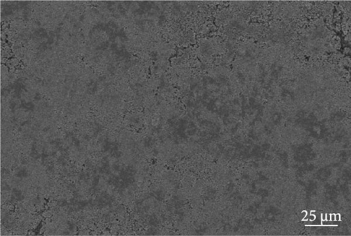
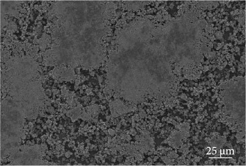
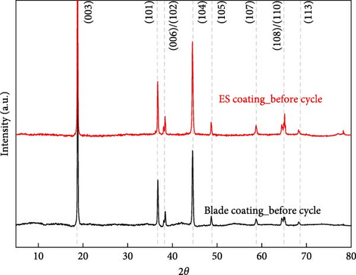
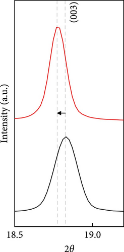
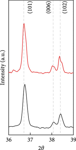
The cathode electrodes produced by conventional blade coating and ES coating were visually very different. First of all, as shown in the SEM images (Figure 2a,b), the surface of the blade coating before cycling has very low porosity and poor dispersion (Figure S1a) of the compositions. In contrast, the surface of the ES coating is very porous, resulting in a very large lithium active area (Figure S1b). To demonstrate the increased porosity of the ES coated cathode, the densities of the two samples were measured (Table S1). The densities of the blade and ES coated cathode are 4.6842 and 2.9011 g/mL, respectively, which is much lower than that of the ES coated sample in the same weight sample. This shows that the volume of the ES coated cathode has been greatly increased, which proves that the porosity has been increased. As shown in Figure 2c–e, all samples exhibited a typical layered α-NaFeO2 structure (space group Rm) with sharp (006)/(102) and (108)/(110) doublet splitting peaks in two samples before cycling, indicating a well-ordered hexagonal layered structure [25, 26]. The intensity ratio of the (003) peak and (104) peak, which usually represents cation mixing, indicates the degree of degradation. If the intensity ratio is more than 1.2, it can be seen that cation mixing does not occur well. In these data, the intensity ratio is 3.24 for blade coating and 3.16 for ES coating before cycling, indicating that the degree of degradation is small for both samples before the cycle (Table S2). Compared to the sample fabricated by conventional blade coating, the (003) peak of the ES coated sample is shifted to a lower angle, which is due to the increased layer spacing caused by electrostatic repulsion of the Li-deficient lattice, and structural degradation occurs [27]. The coating slurries of the two samples were prepared with different solvents. However, no effect of the different solvents was found in the XRD data. XRD data for Pristine NCM811 is shown in Figure S2.
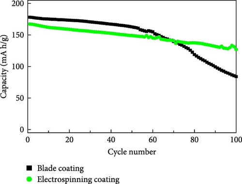
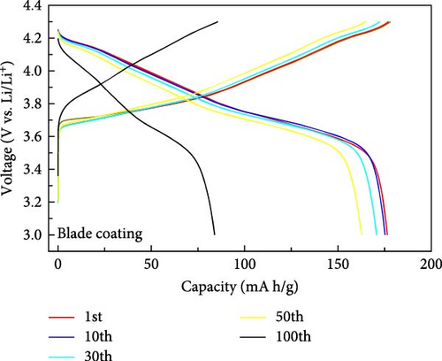
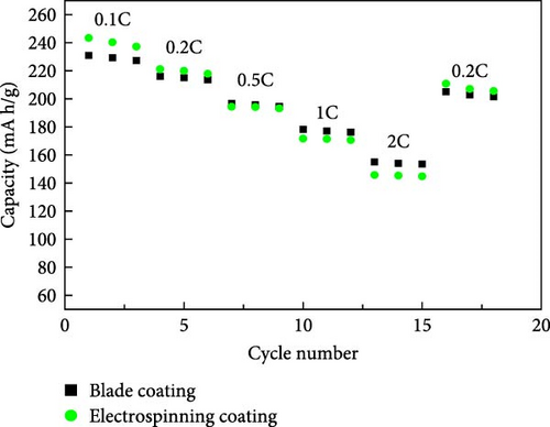
The electrochemical properties of the blade coating and the ES coating were evaluated. The results are shown in Figure 3. The cycling performance characteristics at 1C (Figure 3a), the discharge capacity of the blade coating is 178.3 mA h/g at the initial cycle, and the discharge capacity after 100 cycles is 83.97 mA h/g, with a retention of 47.13%. The discharge capacity of the ES coating is 167.36 mA h/g in the first cycle and 127.17 mA after 100 cycles, which increases the retention to 75.98%. This is attributed to the well-dispersed coating of the cathode slurry on the aluminum collector through the ES coating. To describe the electrochemical performance, Figure 3b,c shows the constant current charge–discharge curves of the blade coating and the ES coating between 3.0V and 4.3 V, respectively. After the 1st, 10th, 50th, and 100th cycles, the discharge capacities of the blade coating are 178.3, 175.22, 162.8, and 83.97 mA h/g, respectively. For the ES coating, the discharge capacities are 167.4, 162.12, 149.13, and 127.17 mA h/g, respectively, which shows less capacity degradation than the blade coating. The retention of the ES coating after 100 cycles is very much improved compared to the blade coating, but the initial discharge capacity is lower. This is due to the structural degradation of the electrostatic repulsion caused by the ES process of applying high voltage, which can be seen in Figure 2d [27]. Figure 3d compares the rate performance of blade coating and ES coating (3.0–4.3 V). The discharge capacities exhibited comparable patterns at 0.1, 0.2, 0.5, 1, and 2C for both the blade coating and the ES coating. When changing to 0.2C after 2C, the ES coating showed a 98.1% decrease in capacity from the initial capacity at 0.2C, while the blade coating showed a 94.93% decrease. ES coating has better cycle reversibility. The results demonstrate that the electrochemical properties of ES coatings are superior to those of blade coatings, with a notable distinction. The reason for this difference is due to the advantages of ES. ES controls the porous film so that the reaction occurs throughout the entire cathode electrode during the cycle. In addition, the specific surface area of the well-dispersed coated cathode slurry is greatly increased, and the pathways between the active material particles are maintained. In contrast, blade coatings with low porosity react with the electrolyte mainly on the surface during the cycle, and the degradation of the surface accelerates as the cycle progresses, resulting in an increase in surface resistance. Therefore, the retention is very low compared to ES coatings.

EIS is a very important analysis for cathode materials as it provides detailed insights into charge transfer resistance, surface film resistance, and ion/electron conductivity. To study the kinetics of the electrodes, EIS measurements of all electrodes were performed at a charge of 4.3 V after formation, 10, 50, and 100 cycles. The Nyquist plots of blade coating and ES coating are shown in Figure 4a,b. The solution resistance between working and counter electrode (Rs) is the resistance that occurs when lithium ions move through the electrolyte and is mainly proportional to the distance between the cathode and anode. However, in this experiment, it was measured with a coin-type cell of the same size, so it has less significance in the above description. The film resistance (Rf) is the solid electrolyte interface (SEI) film resistance, including the ionic transport resistance of Li+ ion through the SEI film. The charge transfer resistance of the cathode (Rct), reflecting the charge transfer reaction at the electrode [28]. As listed, Table 1 shows the change in Rf and Rct for each cycle. In Figure 3b,c, the blade coating shows a significant degradation at 50–100 cycles, so we focused on the increase in EIS resistance from 50 to 100 cycles of each sample. As can be seen, the Rf of the blade coating exhibits a notable increase of 150.4% from 50 cycles to 100 cycles. In the case of ES coating, however, its increase is smaller than that of blade coating, which is 127.8% from 50 cycles to 100 cycles. Also, Rct, which is dominated by charge resistance, shows a similar trend to Rf. From 50 cycles to 100 cycles, the Rct of the ES coating increased by 150.7%, which is smaller than the 186.6% of the blade coating. As a result, it can be concluded that the resistance of the blade coating increased more than that of the ES coating as the number of cycles increased.
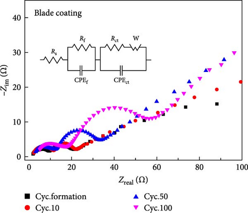

| Sample | Cycle | Rf (Ω) | Rct (Ω) |
|---|---|---|---|
| Blade coating | Cyc.formation | 8.255 | 13.56 |
| Cyc.10 | 10.03 | 12.11 | |
| Cyc.50 | 10.71 | 23.79 | |
| Cyc.100 | 16.11 | 44.39 | |
| Electrospinning coating | Cyc.formation | 11.33 | 13.59 |
| Cyc.10 | 11.74 | 15.75 | |
| Cyc.50 | 12.34 | 27.14 | |
| Cyc.100 | 15.77 | 40.9 | |
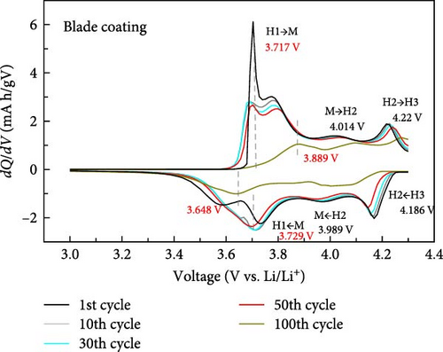
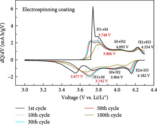
To further investigate the electrochemical behavior during the cycle, the dQ/dV curves of the cathode with blade coating and ES coating between 3.0 and 4.3 V are shown in Figure 5. It can be seen that the first cycle of the blade coating and the ES coating are similar, which means that no redox reaction occurred after ES. For both the blade coating and the ES coating, a total of three phase transitions occurred during the lithiation–delithiation process. It can be seen that the first charge–discharge peak of the blade coating is centered at 3.717 and 3.729 V, and the peak is narrow and sharp. However, after 100 cycles, the transition peaks can be seen to broaden and shift to 3.889 and 3.648 V. For the ES coating, the first charge–discharge peaks are narrow and sharp, centered at 3.748V and 3.742 V. After 100 cycles, the peaks only shift to 3.806 and 3.677 V and are still sharp. The voltage gap difference of the blade coating increases from 0.012V (3.717−3.729 V) to 0.241V (3.889−3.648 V), while the ES coating has a smaller voltage gap change from 0.006V (3.748−3.742 V) to 0.129V (3.806 −3.677 V). This shows that the shape and peak intensity of the dQ/dV curve of the ES coating is very well maintained compared to the blade coating, indicating that the ES coating cathode has excellent circularity. In addition, since the charge/discharge stabilizer is highly dependent on the structure of the cathode, the above results suggest that ES helps to stabilize the structure of Li[Ni0.8Co0.1Mn0.1]O2.
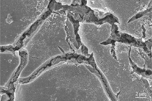
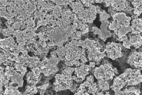
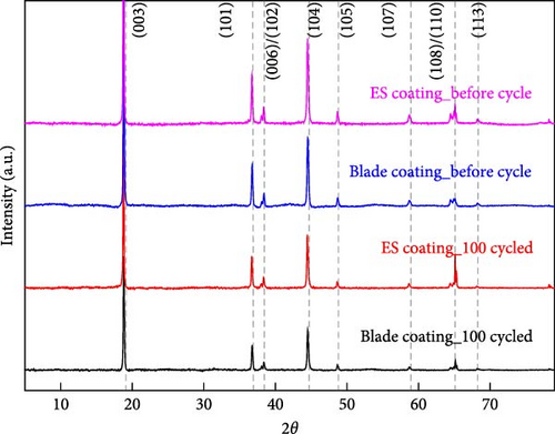
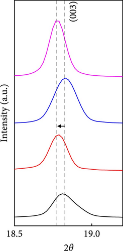
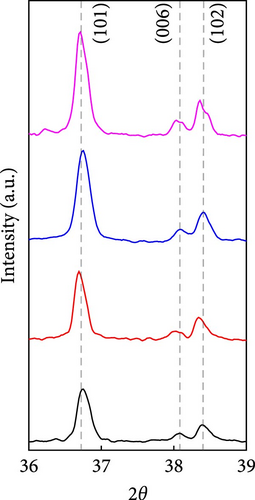
After 100 cycles, both samples were disassembled and both NCM811 cathodes were immersed in DMC for the same time to remove the SEI film on the surface. The surface of the blade coating and the ES coating are still different. In the case of the blade coating (Figure 6a), due to the very dense surface, the active area of the active material in contact area with the electrolyte is relatively small compared to ES coating. On the other hand, the ES coating still has a very large reaction area between the electrolyte and the active material (Figure 6b). Also, after the cycle, there was little change in the volume of both samples (Table S1), but both intensities decreased. Just like before the cycle, after 100 cycles, the (003) peak of the ES coating is shifted to a lower angle, for the same reason as described before (Figure 6c–e). The (006)/(102) and (108)/(110) doublet splitting peaks were still present in both samples. However, the intensity of the blade coating more decreased after the cycle, and it is difficult to say that a clear doublet appeared. This means that the blade coating does not show a clear layered structure compared to the ES coating after the cycle. These results support the conclusion that the degradation of the blade coating after 100 cycles is more severe than that of the ES coated sample.
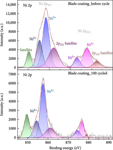
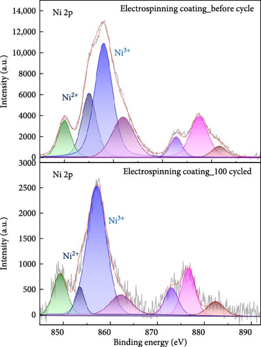
In high nickel NCM cathodes, the before and after cycle chemical oxidation states of the nickel ion play an important role in performance. As shown in Figure 7, the Ni 2p peaks in NCM811 are divided into Ni 2p3/2 and Ni 2p1/2, and the peaks of Ni2+, Ni3+ are important. In general, larger Ni3+, Ni2+ ratio indicates improved energy density and leads to higher battery capacity. Conversely, if the intensity of Ni2+ increases and the Ni3+, Ni2+ intensity ratio decreases, more Ni2+ reduction occurs from Ni3+, which accelerates the formation of rock salt NiO or increases cation mixing [29, 30]. In this paper, the ratio of Ni2+/(Ni2++Ni3+) via peak area was measured to quantitatively analysis the extent of cation mixing and phase transformation. Before cycling, both the blade coating and the ES coating had similar Ni2+/(Ni2++Ni3+). However, after 100 cycles, the blade coating measured about 9% higher than the ES coating, which can be supported by the fact that more cation mixing occurred in the blade coating after cycling. Furthermore, Li 1s, O 1s, F 1s, and P 2p XPS results support that the blade coating degraded more after cycling than ES coating. Figure S3 is the XPS peak of Li 1s. The Li 1s peaks in NCM811 correspond to three peaks of intercalated lithium, LiOH, Li2CO3. Compared to the blade coating, the LiOH, Li2CO3 intensity of the ES coating is lower. This means that the amount of residual Li on the NCM811 surface is reduced. After 100 cycles, the intercalated lithium peak decreased by 77.3% in the blade coating, while it decreased by 55% in the ES coating. This indicates a lower degradation of the ES coating [31]. Figure S4 is the XPS peak of F 1s, which is split into LiF, LixPOyFz, and PVDF. The PVDF peak intensity ratio of the ES coating is relatively higher than that of the blade coating. This indicates that PVDF coexists within the SEI layer or that there is a thin coating of degradation products on top of the binder layer. In addition, the binding energy of the PVDF peak of the ES coating was lower than that of the blade coating both before and after the cycle, indicating that the ES coating formed a denser coating film on the surface, which further retarded degradation. The LiF and LixPFy peaks of the ES coating were much lower than those of the blade coating, indicating that a low-resistance surface layer was formed [32–34]. The O 1s data in Figure S5 is split into C─O, C═O (Li2CO3) and metal oxide peaks. Compared to the blade coating, the C═O peak intensity of the ES coating is lower. This indicates that the amount of residual Li on the surface of the ES coating is quantitatively less. The metal oxide peak represents the M and O bonds on the NCM811 surface. The stronger this peak is, the less structural defects of the NCM811 crystal during charge and discharge cycles, and the less oxygen outflow during side reactions to prevent thermal away. In the case of blade coating, the metal oxide decreased by about 70% after the cycle, but in the case of ES coating, it decreased by about 37% and showed a higher intensity after the cycle compared to blade coating [31]. Finally, Figure S6 shows the XPS peak of P 2 p and enables quantitative analysis of the impedance of the surface. LixPOyFz and phospho-ions (PO43− and PO33−) originated from LiPF6, which is also present after cycling, the NCM surfaces consist of a mixture of LiPF6, LixPOyFz, and even phospho-ions, indicating that the degradation of LiPF6 during cycling at a high rate leads to the continuous generation of SEI layers, which causes the higher impedances. Both before and after the cycle, the LixPOyFz peak intensity of the blade coating is higher than that of the ES coating, which indicates that the surface impedance of the blade coating is higher even after the cycle [35]. These XPS results support the electrochemical results.
4. Conclusion
In this study, we have demonstrated the significant advantages of using ES over traditional blade coating methods for the fabrication of NCM811 cathodes in LIBs. Our findings indicate that the ES technique enhances the cycling performance of the cathode material.
The electrospun cathodes exhibited increased porosity, facilitating a more extensive reaction with the electrolyte. This enhanced reaction mitigates the surface degradation typically observed in blade-coated electrodes, where reactions are predominantly limited to the surface. This is confirmed by the EIS results. For the ES coating, the charge transfer resistance and film resistance after 100 cycles are 40.9 and 15.77 Ω, which is lower than the blade coating (44.39, 16.11 Ω). In addition, the increase in Rf and Rc from 50 to 100 cycles is 127.8% and 150.7%, respectively, which is smaller than 150.4% and 186.6% of the blade coating. Additionally, the electrospun electrodes demonstrated significantly improved cycling stability. Specifically, while blade-coated electrodes showed a capacity retention of 47.13% after 100 cycles at 1C, the electrospun electrodes retained 75.98% of their capacity under the same conditions. This improvement highlights the potential of ES to extend the operational lifespan of LIBs.
Moreover, ES is a versatile and cost-effective process that can be easily integrated into existing manufacturing workflows. Unlike blade coating, which requires heat treatment equipment and energy to remove the solvent, ES evaporates the solvent during the process and offers greater control over the morphology and structure of the cathode materials. The introduction of ES provides new opportunities for the design and fabrication of high-performance electrodes. By enabling the production of porous films, ES can significantly enhance the electrochemical properties of cathodes, thereby contributing to the development of more efficient and durable LIBs.
In summary, the integration of ES into the electrode fabrication process offers a promising pathway to overcome the limitations associated with traditional blade coating methods. This study provides a foundational understanding of the benefits of ES, paving the way for further research, and development in this area. Future work will focus on optimizing the ES parameters and exploring the scalability of this technique for industrial applications. The advancements demonstrated in this study hold significant potential for improving the performance and longevity of LIBs, which are essential for the progression of EVs and portable electronic devices.
Conflicts of Interest
The authors declare no conflicts of interest.
Author Contributions
JinUk Yoo and Dong Chul Kang: conceptualization, formal analysis, investigation, resources, writing–original draft. Hyun Chul Kang: data curation, validation, visualization. Sung Gyu Pyo and Songhun Yoon: writing–reviewing and editing, supervision. JinUk Yoo and Dong Chul Kang contributed equally to this work.
Funding
This work was supported by the National Research Foundation of Korea (NRF) grant funded by the Ministry of Science and ICT (MSIT, Korea) (RS-2023-00255695) and also supported by the Announcement of New Call for Material Parts Technology Development Program by the Ministry of Trade, Industry and Energy (MOTIE), Korea (no. 20014562).
Acknowledgments
This work was supported by the National Research Foundation of Korea (NRF) grant funded by the Ministry of Science and ICT (MSIT, Korea) (RS-2023-00255695) and also supported by the Announcement of New Call for Material Parts Technology Development Program (No. 20014562) by the Ministry of Trade, Industry and Energy (MOTIE), Korea.
Supporting Information
Additional supporting information can be found online in the Supporting Information section.
Open Research
Data Availability Statement
The data that support the findings of this study are available upon request from the corresponding author. The data are not publicly available due to privacy or ethical restrictions.


