Load Frequency Control of Power Systems Integrated With Heterogeneous Controllable Loads: A Hybrid MPC Approach
Abstract
With the increasing participation of flexible loads in power grid regulation, the heterogeneity of flexible loads poses a critical challenge in load frequency control (LFC) of power systems. This paper proposes a novel hybrid model predictive control (HMPC)-based LFC strategy for power systems with heterogeneous controllable loads (HCLs), comprising continuous-type controllable loads (CCLs) and discrete-type controllable loads (DCLs). To the best of our knowledge, this is the first paper to introduce discrete-type controllable resources into the LFC framework and formulate a hybrid predictive model incorporating both continuous and discrete control inputs. Due to the hybrid predictive model involving both continuous and integer decision variables, we employ a mixed-integer linear quadratic programing (MILQP) algorithm to solve the problem and obtain the optimal LFC strategy. Simulation results on a three-area interconnected power system demonstrate that the proposed HMPC-based LFC achieves improved performance over traditional PI-based LFC in terms of overshoot (OS) reduction, oscillation damping, and regulation speed. The effectiveness of the proposed approach depends on the accuracy of the LFC model, which may present challenges in scenarios with significant system uncertainties. Nonetheless, this research contributes an innovative control paradigm for LFC design in power systems with heterogeneous regulation resources.
1. Introduction
1.1. Article Motivation
Frequency stability represents a balance between power supply and demand in an entire power grid, while load frequency control (LFC) is crucial for keeping this balance. Therefore, the LFC plays a key role in ensuring frequency stability and system security [1–3]. In recent decades, large-scale renewable energies have been developed and integrated into power grids to reduce greenhouse gas emissions [4, 5]. The low inertia, intermittency, and uncertainty of these renewable energies pose significant challenges on power system LFC. In addition, high-proportion renewable energy integration has led to a sharp decrease in the proportion of traditional energies. Thus, the capacity of conventional generators which can be used for LFC regulation has been compressed. Consequently, it is unable and uneconomical to rely solely on the traditional generation units for LFC regulation [6–8]. In this context, much attention has been turned to flexible controllable loads at the demand side since the controllable loads can participate in the LFC with the help of advanced information and communication technology and advanced measurement techniques [9, 10].
In a deregulated electricity market, flexibly controllable loads at the demand side are diverse and exhibit heterogeneous characteristics [7, 11]. Regarding the power output characteristics of controllable loads, some can be controlled continuously, while others can only be controlled discretely (e.g., switch-controlled loads). When these heterogeneous controllable loads (HCLs) participate in the LFC through the real-time electricity market, independent system operators (ISOs) have to redesign the corresponding LFC strategy. However, rare relevant research work has been conducted on this issue.
1.2. Literature Review and Research Gaps
1.2.1. LFC Approach Review
1.2.1.1. Improved PID Approaches
In order to improve the performance of traditional PID-based LFC strategy, researchers have proposed some advanced PID control strategies. To deal with the information staleness caused by communication time delay, an age-of-information-aware PI controller was used for LFC design in [12]. Similarly, to address the issue of communication time delay, a robust proportional integral derivative double derivative (PIDD2) controller was introduced for the interconnected power system LFC [13]. To endow the controller with a higher degree of parameter freedom, a new cascaded fractional-order PID (FOI-FOPIDD2) was adopted to design the LFC, where the controller gains were optimized by a squid game optimizer [14]. To support the system inertia against the attenuation caused by renewable energies, the authors in [15] provided a solution combining virtual inertia control with conventional LFC, and developed a fractional-order PID algorithm. In addition, a Kalman-filter PI-based control approach was proposed to formulate the LFC strategy for observing the unmeasurable system states and compensating the original PI controller [16]. Despite the widespread adoption of PID controllers in the industry due to the simplicity of concept and ease of implementation, they exhibit a large limitation when applied to the multi-input multi-output systems.
1.2.1.2. Robust Approaches
The uncertainties in system parameters, information communication, load disturbances, etc., may degrade the performance of the control system. Consequently, numerical studies have been conducted to enhance the robustness of LFC system. For instance, the authors in [17] utilized a feedforward control loop and an integral sliding mode control loop to suppress the disturbances as by loads and renewable energies. In light of the uncertainties of time-varying delay in communication channels, the authors in [18] presented a PI-type robust H-infinity LFC design method via the reciprocally convex inequality. Similarly, to address the issue of time delays, the authors in [19] designed an adaptive delay compensator to compensate the communication delay in the control loop. In response to the potential threat of cyberattacks on communication networks, the authors in [20] proposed a decentralized event-triggered mechanism-based algorithm for updating LFC scheme to fortify the robustness against the cyberattacks. However, since these methods primarily rely on conventional LFC models for controller design, their direct application to hybrid LFC controller design is challenging.
1.2.1.3. Data-Driven Approaches
The data-driven control methodology, which does not depend on accurate mathematical models, has undergone swift advancement in recent years, and its application in the power systems LFC has also begun to be investigated. For example, the authors in [8] proposed a data-driven LFC model via learning from the input–output trajectory instead of the accurate LFC model. For preventing the system frequency from running out of control due to sudden off-grid faults, the authors in [21] developed a fault-tolerant LFC scheme based on the deep meta-reinforcement learning algorithm for islanded microgrids. In addition, the deep reinforcement learning algorithm was also applied to the power system LFC against renewable energy uncertainties [22]. Unlike machine learning-based methods, a data-driven LFC scheme relying on the input and output data of the power system instead of the dynamic model of power systems was proposed in [23], where an event-triggered strategy was used to reduce the communication and computation burden. The authors in [24] introduced a model-free adaptive dynamic programing algorithm for the LFC design via utilizing measured data to learn the optimal gain without relying on model parameters. The aforementioned data-driven methods typically necessitate a considerable investment of time for model training, and the decision-making process of these models can be challenging to be interpreted, potentially leading to certain limitations in their practical application.
1.2.1.4. Model Predictive Control (MPC)-Based Approaches
The MPC approach has been effectively applied across various engineering fields, including process industries, power electronics, and energy systems. Recently, researchers have begun to study its application in the LFC of power systems. For instance, to enhance the disturbance rejection capability and improve the control performance of the LFC, the adaptive MPC approaches were employed to design the LFC controller for hybrid power systems integrated with multiple energies [25, 26]. To reduce the frequency regulation burden of conventional generators, various adjustable resources have been introduced into power systems. In [27], a diverse mix of energy storage was used for LFC performance enhancement, and a new MPC approach is proposed to design the load frequency controller of microgrids. In [28], battery energy storage systems were introduced to participate in the power system LFC, and a two-layer MPC algorithm was developed to generate the optimal control signals. Towards a multiarea power system with hybrid renewable generators and storage devices, the authors in [29] established the predictive model of the system, and utilized a transient search optimization algorithm to optimize the MPC-based LFC scheme. With the help of vehicle-to-grid technology, electric vehicles (EVs) supported by some advanced control technologies can provide auxiliary frequency regulation service [30]. For instance, an optimal MPC was applied for the LFC of the islanded power grid with EVs [31]. To track the LFC signal from an ISO, an MPC method was proposed to coordinate plug-in hybrid EVs, controllable loads, and cogeneration units [32]. To keep the SoC balance of hybrid energy storage systems and reduce the computational burden of controllers, a distributed MPC method was utilized to design the LFC strategy for multiarea power systems [33]. The above reported studies mainly focus on using the conventional MPC or the improved MPC to design the LFC for the power systems integrated renewable energies and energy storage units. However, the LFC predictive models established in the reported studies mathematically fall under the category of linear quadratic programing (LQP) models, as both the decision variables and state variables of these models are continuous. When hybrid HCLs participate in the LFC of power systems, the corresponding model decision variables may simultaneously include both continuous variables and discrete variables (such as binary variables, integer variables, etc.). At this point, there is still a lack of related research on how to design the LFC for power systems.
1.2.1.5. Improved PID+MPC Approaches
To address the adverse effects of fluctuations in renewable energy sources like PVs and wind power on frequency stability, a new class of LFC strategies have been developed in recent years. These strategies combined the enhanced PID algorithms with MPC techniques to design LFC controllers for complex power systems. The LFC controllers were implemented in two configurations: series-connected [34–37] and parallel-connected [38]. In the series-connected configuration, the MPC cascaded with enhanced PID (i.e., FOPID and PIDN) or the enhanced PID cascaded with MPC approaches were proposed to improve frequency regulation performance of multiarea power systems. Some intelligent optimization algorithms, such as the grasshopper optimization algorithm, sooty tern optimization algorithm, and salp swarm algorithm, were employed to determine the optimal parameters for the controllers. While in the parallel-connected configuration, the MPC in parallel with FOPID were used to design the LFC controller for multiarea interconnected power systems. Benchmark tests confirmed the superior frequency regulation capabilities of these methods over conventional PID and MPC algorithms in the LFC of complex power systems. However, the aforementioned research has exclusively considered continuously adjustable power sources for the power system LFC, while neglecting potential contributions from flexible loads (particularly switch-controlled adjustable loads) in frequency regulation.
1.2.2. Flexible Loads Participating in LFC
In recent years, flexible controllable loads have played an important role in the LFC, and related research has been carried out successively. The authors in [39] proposed a general framework for introducing demand response (DR) into the LFC model and analyze the impact of the DR communication delay on the LFC performances. Considering communication delay and sampling effect, the authors in [40] designed an optimal LFC scheme to regulate DR and generation units. Recently, much attention has been paid to the heterogeneous properties of flexible controllable loads. For instance, in [41], a two-level control framework was proposed to coordinate the energy consumption of heterogeneous loads. In [42], a distributed optimization framework was introduced to control large-scale heterogeneous loads. In [43–45] different control technologies were adopted to coordinate heterogeneous thermostatically-controlled loads (TCLs) at the aggregator’s level. While the aforementioned studies have extensively explored the involvement of heterogeneous loads in power system frequency regulation, the adopted load models are almost continuous in their mathematical formulation, failing to account for cases where the load models are discrete.
1.2.3. Hybrid Model Predictive Control (HMPC) Application
In recent decays, the HMPC theory has been developed to address the controller design for hybrid industrial systems, where control variables include discontinuous components, such as on/off switches, gears, speed selectors, etc. [46]. The application fields of HMPC cover control systems of behavioral medical devices [47], production inventory systems [48], HVAC systems [49], power electronic converters [50], and more, demonstrating exceptional control performances. The power system LFC with numerous HCLs also exhibits the aforementioned hybrid characteristics, and thus the HMPC theory can also provide a theoretical foundation for the corresponding LFC design. However, to the best of our knowledge, the existing research has hardly addressed how to utilize this theory for LFC design.
1.2.4. Current Research Gaps
Based on a comprehensive review of existing literature, the key differences between this study and existing typical work are highlighted in Table 1 and the main research gaps and motivations are identified as follows:
| References | Research focus | Regulation resources | Constraints | Model type | Control methodology |
|---|---|---|---|---|---|
| [13] | Time delay | Conventional generators | Neglect | Continuous | Robust PIDD2 |
| [16] | Model uncertainties | Conventional generators | Neglect | Continuous | KF-PI control |
| [19] | Time delay | Conventional generators, DRs | Neglect | Continuous | Robust control |
| [23] | Model uncertainties | Conventional generators, DGs | Neglect | Continuous | Data-driven approach |
| [24] | Model uncertainties | Conventional generators | Neglect | Continuous | Zero-sum game and ADP |
| [26] | Disturbance rejection | Conventional generators, DGs | Neglect | Continuous | Adaptive MPC |
| [28] | Model uncertainties | Conventional generators, ESs | Neglect | Continuous | Robust MPC |
| [29] | LFC parameter optimization | Conventional generators, ESs | Consider | Continuous | TSO-MPC |
| [34] | New-type LFC | Conventional generators, DGs | Neglect | Continuous | Cascaded MPC and FOPID |
| [35] | New-type LFC | Conventional generators, DGs | Neglect | Continuous | Cascaded MPC and FOPID |
| [37] | New-type LFC | Conventional generators, DGs | Neglect | Continuous | MPC- (1+PID) |
| This study | New LFC model and approach | Conventional generators, HCLs | Consider | Hybrid | Hybrid MPC |
- •
The existing studies on the power system LFC predominantly rely on continuous mathematical models of power system dynamics. However, when HCLs (e.g., thermostatically controlled loads and on/off loads) participate in the LFC, their discrete nature (binary/integer variables) introduces a new challenge for controller design. The current MPC-based LFC schemes fail to adequately address the co-optimization of continuous and discrete decision variables in LFC predictive models, limiting practical applicability.
- •
Since existing LFC designs seldom consider control inputs with both continuous and discrete variables, this paper presents a novel method accounting for HCLs that comprise continuous-type controllable loads (CCLs) and discrete-type controllable loads (DCLs).
1.3. Article Contributions and Organization
- 1.
The models of the HCLs are formulated in the power system LFC framework. The HCLs are categorized into CCLs and DCLs. The former are represented by first-order continuous dynamics, and the latter are expressed as integer variables.
- 2.
A novel hybrid predictive model is established for the LFC design of the power systems integrated with the HCLs. The heterogeneous characteristics of controllable loads, the system operation constraints, and the LFC objective are fully considered in this model.
- 3.
A rolling optimization algorithm is proposed to solve the hybrid predictive model of the LFC. Given that the hybrid predictive model is a typical mixed-integer LQP (MILQP) problem, a rolling interactive iterative solving process is provided for calculating the optimal LFC command based on the MILQP method.
- 4.
The proposed HMPC algorithm overcomes key limitations of conventional MPC-based LFC schemes in discrete control variable handling, while offering a unified approach for LFC systems with mixed continuous-discrete control inputs.
The rest of this article is organized as follows: Section 2 introduces the framework and model of HCLs participating in the LFC. Section 3 formulates the LFC model of the HCL-integrated power systems. Section 4 designs the LFC strategy based on the HMPC algorithm. Section 5 conducts the simulations. Finally, Section 6 draws a conclusion for this article.
2. Framework and Model of HCLs Participating in LFC
The diagram of HCLs participating in the LFC of a power system area is shown in Figure 1. As the figure shows, a power system area includes conventional generators, renewable energies, and controllable and uncontrollable loads, and it is connected to its neighboring areas through some tie lines. This article states that renewable energies and uncontrollable loads in the LFC framework are deemed as power disturbance sources. The control center assigns the LFC commands to the regulation resources (i.e., conventional generators and controllable loads) to keep the system frequency stable and maintain the tie-line power at its scheduled value.
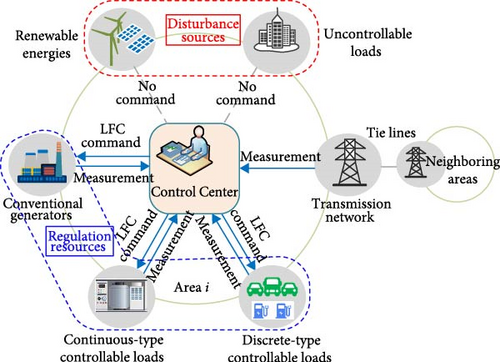
The controllable loads are the energy-intensive load aggregators under contract with the power system operator, and they can be categorized into CCLs and DCLs according to the power output characteristics. The power of CCLs can be adjusted continuously in a specific range. The TCLs (e.g., heaters, chillers, and central air conditioners) are typically CCLs. The DCLs include interruptible and laddered loads (e.g., none-V2G EVs), and their power response is significantly discontinuous and stepwise.
3. Model of Power System Integrated With HCLs
3.1. LFC Model Structure
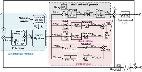
This paper presents the HMPC-based LFC framework of an HCL-integrated power system area shown in Figure 2. Under this framework, the control center of the ith area measures the system frequency deviation and tie-line power deviation to calculate the area control error (ACE) first. Then, a PI regulator determines the area regulation requirement (ARR) based on the ACE. Subsequently, the ARR is distributed to the frequency regulation participants (e.g., the conventional generators and the controllable loads) according to the HMPC scheme. Finally, the participants respond to the frequency regulation command from the control center by adjusting their power output. The variables and parameters in Figure 2 are defined in the nomenclature part.
3.2. Hybrid State-Space Model
- 1.
(Ai, (BC,i BD,i)) is controllable.
- 2.
(Ai, CM,i) is observable.
- 3.
has full rank.
Since the above conditions (2) and 3) hold, we can easily estimate the states Xi and the disturbances Wi according to the method provided by James et al. [51]. Thus, this paper directly use Xi and Wi to replace their estimated values and for brevity.
4. LFC Strategy Design Based on HMPC
4.1. Hybrid Predictive Model
4.1.1. Discrete Hybrid State-Space Model
4.1.2. LFC Objective Function
4.1.3. Operational Limitations
The hybrid predictive model (13) is a typical MILQP problem since the objective function is quadratic, the constraints are linear, and the decision vector (control input vector) includes both continuous and integer variables.
According to the receding horizon principle, by repeating the entire optimization procedure at time k + 1, the control law of the LFC model (7) will be updated based on the optimal predictive control law obtained from solving the hybrid predictive model (13).
Remark 1. The system stability can be analyzed using Lyapunov stability theory. Bemporad and Morari [46] proposed a theorem to ensure the stability of the HMPC-based closed-loop system, supported by rigorous theoretical proof. Since the stability proof is not the primary focus of this paper, it is omitted here. As noted in Subsection 3.2, the LFC model (7) is controllable and observable. According to the theorem proposed in [46], by appropriately selecting prediction NY and control horizon NC as well as positive definite weighting matrices QY,i, RC,i, and RD,i, the existence of a feasible solution for model (13) and the system stability can be well guaranteed.
4.2. LFC Strategy Based on MILQP Algorithm
- 1.
Compute the discrete system matrixes , , , , , and according to the system parameters, and preset the weight matrixes QY,i, RC,i, and RD,i, the predictive horizon NY, and the control horizon NC.
- 2.
Estimate all the states Xi and disturbances Wi in area i, receive the frequency deviation Δfj from the neighboring areas and transmit its own Δfi to the neighboring areas.
- 3.
Solve the hybrid predictive model (13) by the MILQP algorithm to calculate the optimal continuous control command sequence and the optimal discrete control command sequence .
- 4.
Choose the first values in the above two sequences as the control commands if the hybrid predictive model (13) is feasible at instant k,that is, and . Otherwise, remain the control command at the previous instant, that is, UC,i(k) = UC,i(k − 1) and UD,i(k) = UD,i(k − 1).
Remark 2. The coupled component in the state-space equation is only related to the frequency deviation Δfj, not all the states Xj. This can be seen from the LFC framework shown in Figure 2. Therefore, two adjacent areas only need to exchange the frequency deviation signal with each other. Since Δfj is the first element of the vector Xj, we use to denote Δfj for ease of description.
The solution process of the HMPC-based LFC strategy for each power system area is described in Algorithm 1.
-
Algorithm 1: HMPC algorithm for the ith area.
-
Input: QY,i, R C,i, R D,i, NY,i, NC,i, and system parameters in model (13);
-
Output:UC,i(k) and UD,i(k);
-
Formulate LFC problem as MILQP model (13); while time
-
k ≤ kmaxdo
-
Estimate Xi(k) and Wi(k), receive from neighboring areas, and transmit to neighboring areas;
-
Employ Gurobi optimizer to solve model (13);
-
if model (13) is feasible then
-
;
-
;
-
else
-
UC,i(k) = UC,i(k − 1);
-
UD,i(k) = UD,i(k − 1);
-
end
-
k ← k + 1;
-
end
5. Case Studies
5.1. Parameters of Test System
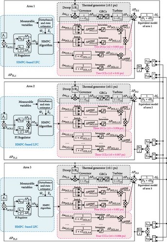
Based on a three-area power system benchmark [25], we develop a simulation model (as Figure 3 shown) to validate the proposed HMPC-based LFC strategy. Each power system area in this model incorporates both CCLs and DCLs. The system parameters are provided in Table 2, while the HCL parameters are detailed in Table 3.
| Area | Di (pu/Hz) | Hi (s) | Ri (Hz/pu) | TG,i (s) | TT,i (s) | βi (pu/Hz) | γij (pu/Hz) | (pu) | (pu/s) |
|---|---|---|---|---|---|---|---|---|---|
| 1 | 0.015 | 0.1667 | 3.00 | 0.08 | 0.40 | 0.3483 |
|
(−0.1, 0.1) | (−0.001, 0.001) |
| 2 | 0.016 | 0.2017 | 2.73 | 0.06 | 0.43 | 0.3827 |
|
(−0.1, 0.1) | (−0.001, 0.001) |
| 3 | 0.015 | 0.1247 | 2.82 | 0.07 | 0.30 | 0.3692 |
|
(−0.1, 0.1) | (−0.001, 0.001) |
| Area | n | TCCL,i (s) | (pu) | m | (pu) | |
|---|---|---|---|---|---|---|
| 1 | 2 | 0.5 | (−0.010, 0.010) | 2 | 0.001 | (−5, −4, −3, −2, −1, 0, 1, 2, 2, 3, 4, 5) |
| 2 | 3 | 0.35 | (−0.007, 0.007) | 3 | 0.001 | (−4, −3, −2, −1, 0, 1, 2, 2, 3, 4) |
| 3 | 4 | 0.2 | (−0.006, 0.006) | 4 | 0.001 | (−2, −1, 0, 1, 2) |
In our test system, we define the power rating of conventional generators and CCLs by their operational limits (minimum and maximum active power output in per-unit (pu) values, 1 pu = 1 GW). For DCLs, the power rating corresponds to their available operating gears. The specific limits for each frequency regulation resource are enumerated in Tables 2 and 3.
In the case studies, the parameters of the proposed HMPC-based load frequency controller are empirically tuned through extensive simulation studies to achieve satisfactory performance under various operating conditions(Table 4 for detailed values). Although this experimental approach produces practically viable results, we recognize that systematic parameter optimization (e.g., the optimization-based methods proposed in [14, 29]) could potentially improve control performance. Nevertheless, since controller parameter optimization falls beyond the scope of this study, we defer this investigation to future work.
| Area | PI parameters | HMPC parameters | |||||
|---|---|---|---|---|---|---|---|
| kP,i | kI,i | NY | NC | Q Y,i | RC,i | RD,i | |
| 1 | 0 | 0.3 | 5 | 2 | 1.65 | diag{0.2, 0.8, 0.8} | diag{2, 6} × 10−6 |
| 2 | 0 | 0.2 | 5 | 2 | 2.8 | diag{0.15, 0.85, 0.85} | diag{2, 4, 8} × 10−6 |
| 3 | 0 | 0.4 | 5 | 2 | 0.45 | diag{0.18, 0.8, 0.8, 0.8, 0.8, 0.8} | diag{3, 5, 6, 6} × 10−6 |
5.2. Simulation and Analysis
The simulation tests are carried out on a PC with an 8-core Intel i7-6700K CPU (4.0 GHz) and 16 GB RAM, using MATLAB/Simulink. The MILQP model was solved with Gurobi optimization software. The average computation time per control decision ranges from 0.03 to 0.06 s, which is well within the 0.1 second sampling period, ensuring real-time feasibility.
5.2.1. Simulation Results Under Step Load Disturbance
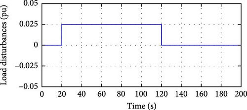
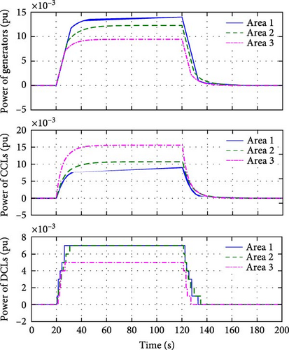
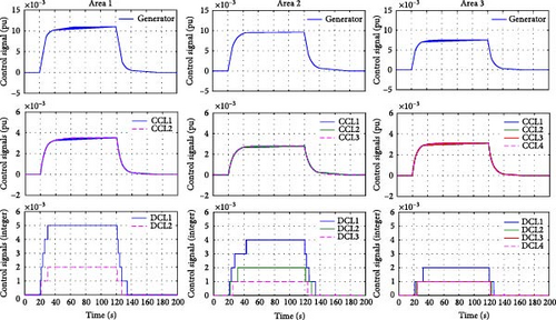
For simplicity, we assume that the same step load disturbance occurs in the three areas. The step load disturbance is set as: in the initial period, the load disturbance ΔPD = 0; at 20 s, ΔPD = 0.0025 pu; at 120 s, ΔPD = 0. The step load disturbance in three areas is given by Figure 4, and the system responses to the disturbance are show in Figures 5–7.
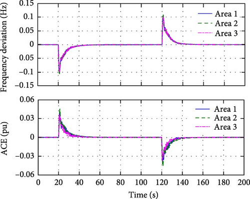
From the frequency deviation and ACE curves in Figure 5 we can see that the frequency deviation and ACE in the three regions are quickly restored to zero. The maximum frequency deviation and the maximum ACE are 0.115 Hz and 0.045 pu, respectively, and the adjustment time is about 20 s.
Figures 6 and 7 illustrate the power outputs and the control signals of the generators, the CCLs, and the DCLs, respectively. We can see that after the step load disturbances occur, the generators, the CCLs, and the DCLs quickly adjust their power in response to the LFC commands of each area, while satisfying their output constraints. The results also show that the power output curves of the generators and the CCLs are continuous, while those of DCLs are discrete. It should be noted that the power output level and adjustment time are determined by the HMPC algorithm based on the corresponding hybrid predictive model, and the main reason for the slightly longer adjustment time given by the HMPC algorithm is to minimize the overshoots (OSs) of the frequency and ACE.
5.2.2. Simulation Results Under Ramp Load Disturbance
In this case, we test the performances of the proposed LFC strategy under ramp load disturbances. The profiles of the ramp load disturbances are shown in Figure 8. The results under ramp load disturbances are shown in Figures 9–11.
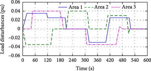
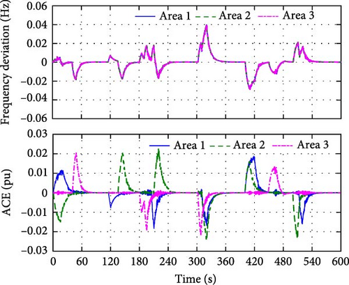
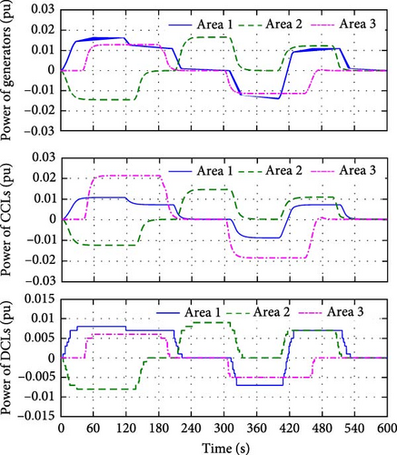
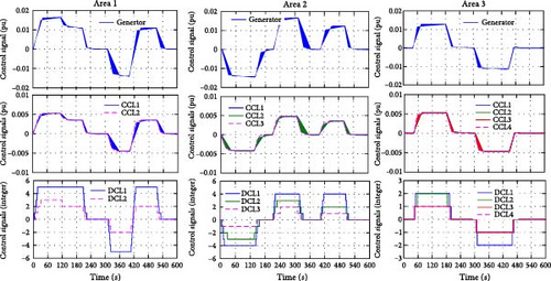
Figure 9 illustrates that the proposed LFC strategy can drive the system frequency deviation and the ACE convergence to zero under the frequent load fluctuations. Under the given load disturbances, the maximum frequency deviation and the maximum ACE are only 0.04 Hz and 0.025 pu, respectively. Furthermore, there is no overshoot (OS) in both frequency deviation and ACE response curves.
The power outputs and the control signals of the generators, the CCLs, and DCLs are shown in Figures 10 and 11. It can be seen that the generators, the CCLs, and the DCLs quickly adjust their power to respond to the LFC demand under their physical constraints. The load disturbance curves in Figure 8, the power output curves in Figure 10 and the control signals curves in Figure 11 illustrate that the total power increment matches the load deviation in each area. This indicates that under normal load disturbance conditions, each area is responsible for its power balance to reduce the cross-regional power support, which can help to alleviate the tie-line power fluctuations.
5.2.3. Performance Comparison Analysis
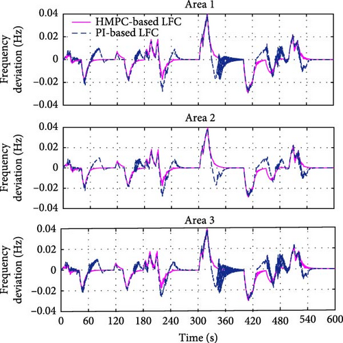
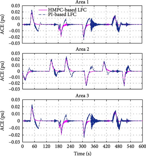
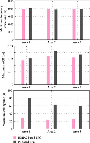
A comparative analysis of the proposed HMPC and conventional PI-based LFC schemes under identical ramp disturbances (as Figure 8 shown) is presented in Figures 12 and 13, and the corresponding quantitative performance metrics of the two schemes are summarized in Figure 14. The comparative results in Figure 14 demonstrate that under identical load disturbances, the HMPC-based LFC and the PI-based LFC yield comparable magnitudes of maximum frequency deviation and ACE. However, the HMPC-based LFC achieves 2.5 times faster settling time (ST), the oscillation-free monotonic convergence without OS, and the superior convergence stability compared to the PI-based LFC.
5.2.4. Parameter Sensitivity Analysis
Considering that the LFC controller design is usually based on a simplified equivalent model of the power system, this study selects two key parameters (the system inertia constant [Hi] and the damping constant [Di]) for sensitivity analysis to evaluate the impact of model parameter uncertainties on control performances. In the tests, these two parameters are varied by gradients of ±10%, ±20%, and ±30%, and a step load disturbance (0.05 pu) is applied. We observe the system frequency response and focus on three dynamic performance indicators: OS, undershoot (US), and ST. The parameter sensitivity test results shown in Table 5, where the bolded row represents the case with normal system parameters. The results indicate that: (1) the proposed controller can maintain system stability within ±30% parameter variation range, but the ST tends to increase as parameters deviate from their nominal values; (2) the OS is unaffected by the changes in Hi and Di; and (3) the US shows a negative correlation with system parameters, decreasing as Hi and Di increase.
System parameters (Hi and Di) |
Area 1 | Area 2 | Area 3 | ||||||
|---|---|---|---|---|---|---|---|---|---|
| OS (Hz) | US (Hz) | ST (s) | OS (Hz) | US (Hz) | ST (s) | OS (Hz) | US (Hz) | ST (s) | |
| ↑+30% | 0 | −0.141 | 16.5 ↑ | 0 | −0.160 | 16.9 ↑ | 0 | −0.149 | 16.7 ↑ |
| ↑+20% | 0 | −0.145 | 16.6 ↑ | 0 | −0.166 | 16.5 ↑ | 0 | −0.154 | 16.8 ↑ |
| ↑+10% | 0 | −0.150 | 16.6 ↑ | 0 | −0.171 | 16.9 ↑ | 0 | −0.156 | 16.6 ↑ |
| Normal values | 0 | −0.165 | 15.4 | 0 | −0.184 | 14.6 | 0 | −0.166 | 15.3 |
| ↓−10% | 0 | −0.165 | 16.1 ↑ | 0 | −0.189 | 16.6 ↑ | 0 | −0.167 | 16.3 ↑ |
| ↓−20% | 0 | −0.179 | 16.2 ↑ | 0 | −0.199 | 16.9 ↑ | 0 | −0.175 | 16.5 ↑ |
| ↓−30% | 0 | −0.190 | 18.3 ↑ | 0 | −0.213 | 16.8 ↑ | 0 | −0.186 | 17.0 ↑ |
6. Conclusion
For the problem of both CCLs and DCLs participating in the LFC, this article provides an HMPC algorithm to design the LFC strategy of power systems. The CCLs and the DCLs are modeled with first-order continuous dynamics and integer variables. The hybrid predictive model used for the LFC design is formulated to be an MILQP model. The real-time LFC strategy is obtained by solving the MILQP model in a rolling fashion. Simulation results illustrate that the proposed HMPC-based LFC can optimally coordinate the CCLs, the DCLs, and the conventional generators to satisfy the frequency regulation demands, and both the frequency deviation and the ACE can be restored to zero with small OSs after load disturbances occur. In addition, the proposed HMPC-based LFC performs better in overshoot, regulation speed, and oscillation suppression than the PI-based LFC.
Future research should focus on optimizing controller parameters using advanced optimization algorithms and enhancing the robustness of the proposed HMPC-based LFC system against parameter uncertainties via disturbance rejection design. In addition, since the solution time for the MILQP problem grows exponentially with the system size, how to reduce the model solution time to meet the real-time requirements of the LFC in large-scale power systems remains a challenge. Scaling down model size through model reduction techniques, enhancing solution efficiency via advanced heuristic algorithms (e.g., genetic algorithms, simulated annealing algorithms, and other AI-driven algorithms), and alleviating computational load with distributed algorithmic architectures (e.g., distributed HMPC) are all potential solutions.
Nomenclature
Nomenclature
-
- ACE:
-
- Area control error
-
- ARR:
-
- Area regulation requirement
-
- CCL:
-
- Continuous-type controllable load
-
- DCL:
-
- Discrete-type controllable load
-
- DR:
-
- Demand response
-
- GRC:
-
- Generation rate constraint
-
- EV:
-
- Electric vehicle
-
- HCL:
-
- Heterogeneous controllable load
-
- MPC:
-
- Model predictive control
-
- HMPC:
-
- Hybrid MPC
-
- LFC:
-
- Load frequency control
-
- MILQP:
-
- Mixed-integer linear quadratic programing
-
- PID:
-
- Proportional integral derivative
-
- TCL:
-
- Thermostatically-controlled load
-
- pu:
-
- Per unit
-
- s.t:
-
- subject to
Indices and Sets
-
- i:
-
- Index of power system area
-
- N:
-
- Number of neighboring areas
-
- c:
-
- Index of CCL
-
- n:
-
- Number of CCLs
-
- d:
-
- Index of DCL
-
- m:
-
- Number of DCLs
-
- :
-
- Real number set
-
- :
-
- Integer set
-
- k:
-
- Index of time step
-
- Superscript min:
-
- Minimum value of corresponding variable
-
- Superscript max:
-
- maximum value of corresponding variable
Variables
-
- Δfi:
-
- Frequency deviation (Hz)
-
- ΔPT,i:
-
- Power increment of the turbine (pu)
-
- ΔPG,i:
-
- Power increment of the governor (pu)
-
- ΔPTL,i:
-
- Tie-line power deviation (pu)
-
- δACE,i:
-
- Area control error (pu)
-
- ΔPP,i:
-
- Proportional output of the PI regulator (pu)
-
- ΔPI,i:
-
- Integral output of the PI regulator (pu)
-
- ΔPR,i:
-
- Area regulation requirement (pu)
-
- ΔuG,i:
-
- Control input of the thermal generator (pu)
-
- ΔPD,i:
-
- Power disturbance of loads and renewable energies (pu)
-
- ΔPCCL, c:
-
- Power increment of the cth CCL (pu)
-
- :
-
- Total power increment of CCLs (pu)
-
- ΔPDCL, d:
-
- Power increment of the dth DCL (pu)
-
- :
-
- Total power increment of DCLs (pu)
-
- ΔuCCL, c:
-
- Control input of the cth CCL (pu)
-
- ΔuDCL, d:
-
- Control input of the dth DCL
-
- Xi:
-
- State vector
-
- Wi:
-
- Variable
-
- UC,i:
-
- Continuous control input vector
-
- :
-
- Optimal value of UC,i
-
- UD,i:
-
- Continuous control input vector
-
- :
-
- Optimal value of UD,i
-
- Yi:
-
- Output vector
-
- :
-
- The estimated state vector
-
- :
-
- The estimated disturbance variable
Parameters and Matrixes
-
- TG,i:
-
- Time constant of the governor (s)
-
- TT,i:
-
- Time constant of the turbine (s)
-
- TCCL,i:
-
- Time constant of the CCL (s)
-
- Ri:
-
- Droop coefficient of the thermal generator (Hz/pu)
-
- Hi:
-
- Inertia constant (s)
-
- Di:
-
- Damping constant (pu/Hz)
-
- βi:
-
- Frequency bias coefficient (pu/Hz)
-
- γij:
-
- Tie-line synchronizing coefficient between area i and j (pu/Hz)
-
- kP,i:
-
- Proportional coefficients of the PI regulator
-
- kI,i:
-
- Integral coefficients of the PI regulator
-
- NY:
-
- Prediction horizon
-
- NC:
-
- Control horizon
-
- Ai:
-
- State matrix
-
- Aij:
-
- Interaction matrix between area i and j
-
- BC,i:
-
- Continuous control input matrix
-
- BD,i:
-
- Discrete control input matrix
-
- Fi:
-
- Disturbance input matrix
-
- Ci:
-
- Output matrix
-
- QY,i:
-
- Weighting matrix of output vector
-
- RC,i:
-
- Weighting matrix of continuous input vector
-
- RD,i:
-
- Weighting matrix of discrete input vector.
Conflicts of Interest
The authors declare no conflicts of interest.
Funding
No funding was received for this research.
Open Research
Data Availability Statement
There are no research data available to be shared.


