Mechanochemically Boosting Additive for Robust Si/C Anodes in High-Energy-Density Li-Ion Batteries
Abstract
Silicon (Si) is regarded as one of the most promising anode materials for Li-ion batteries (LIBs) owing to its high specific capacity of 3579 mAh g–1 and low redox potential. However, large volume changes in Si during lithiation/delithiation cycles lead to microcrack formation in the electrode and rupture of the solid electrolyte interphase (SEI) layer, resulting in poor cycling stability. In this regard, Si/carbon (Si/C) composites have been widely explored to mitigate the volume changes in Si and increase the Li-ion kinetics. However, the mechanochemically unstable SEI layer is still challenging for the development of high-energy-density Si/C anodes. In this study, polyvinylpyrrolidone (PVP) is introduced as a mechanochemically boosting electrode additive (MBEA) to enhance the chemical and mechanical stability as well as the electrochemical performance of Si/C composite anodes in LIBs. PVP can stabilize the anode interface by forming a robust inorganic-rich SEI layer, which improves the Li-ion kinetics owing to its chemical stability and mechanical integrity. Furthermore, PVP on the surface of Si/C composite anodes enhances the binding affinity, including the adhesion and cohesion properties of the active materials. In these regards, the Si/C anodes with MBEA (Si/C-MBEA) exhibit excellent electrochemical performance with alleviated volume changes compared with the pristine Si/C anode. This study presents a facile and practical approach for the development of high-performance Si-based anodes for next-generation LIBs.
1. Introduction
Li-ion batteries (LIBs) have been extensively employed as energy storage devices because of their high-energy-density and suitable operating voltage for wireless electronics, electric vehicles (EVs), and renewable energy storage systems [1–5]. Although graphite is still widely used as an anode material in LIBs, its low specific capacity of 372 mAh g–1 and limited rate capability present challenges for the development of high-energy-density and high-power LIBs [4, 6]. Therefore, there is a pressing need to develop new anode materials that can overcome the limitations of graphite. Silicon (Si) has been regarded as one of the most promising anode materials owing to its extremely high specific capacity of 3579 mAh g–1 (Li15Si4) and low redox potential (0.4 V vs. Li/Li+) in LIBs [7–10]. However, the substantial volume changes in Si associated with Li pose significant challenges to the stable electrochemical performance of LIBs [11–13]. The repetitive volume expansion and contraction of Si during lithiation and delithiation cycles cause severe microcracks in Si anodes. As a result, the bare Si surface is exposed to the liquid electrolyte, leading to the continuous evolution of solid electrolyte interphase (SEI) layers and consumption of the liquid electrolyte [14, 15]. During cycling, these parasitic reactions result in the formation of thick SEI layers and the pulverization of the electrode, thereby impeding efficient charge transfer [16].
To address these issues, many strategies have been introduced to mitigate volume changes in Si in high-energy-density LIBs. Nanostructured Si has shown improved electrochemical properties, with void spaces buffering the volume expansion of Si in LIBs [17, 18]. However, nano-Si is not suitable for commercial LIBs because of its limited volumetric energy density. Furthermore, the use of pure Si anodes in practical LIBs is challenging because of electrode swelling and safety issues. To address these problems, Si/carbon (Si/C) composite anodes have been extensively studied [18–20]. Si uniformly distributed within Si/C exhibits mitigated volume changes, while the carbon provides electronically conducting pathways that compensate for the low electronic conductivity of Si. Various studies have demonstrated that Si/C composite anodes exhibit outstanding electrochemical performance with reduced volume changes in LIBs [18, 21, 22]. However, the mechanochemically unstable SEI layer and rupture of Si/C composite anodes lead to poor cycling performance with continuous electrolyte consumption in LIBs.
To ensure stable cycling performance with negligible degradation of the Si/C composite anodes, the initially formed SEI layer should protect the anode interface with high mechanical integrity and facilitate fast Li-ion transport. Given that Si/C composite anodes exhibit reduced volume changes compared to pure Si anodes, the formation of a robust SEI layer is critical for achieving stable cycling and high-rate performance in LIBs. Lithium fluoride (LiF) is a well-known inorganic SEI component with high Li-ion conductivity, chemical stability, and mechanical integrity [23–28]. Thus, a LiF-rich SEI layer has been widely employed using various strategies, such as the adoption of fluoroethylene carbonate (FEC) as an electrolyte additive and aluminum fluoride (AlF3) protective layer coating [29, 30]. Lithium nitride (Li3N) is also well-known inorganic SEI component with a high ionic conductivity (~10−3 S cm⁻1) and a high Young’s modulus of 48 GPa, facilitating rapid Li-ion transport [31–34]. Therefore, a lot of studies have introduced employing Li3N as a stable and effective SEI component in Si-based anodes for LIBs. However, prolonged cycling can lead to the rupture of Si/C composite anodes and continuous consumption of Li ions and electrolyte additives, resulting in fast capacity fading in LIBs. Therefore, it is essential to develop a facile and effective strategy for constructing a robust SEI layer to prevent the continuous decomposition of electrolytes and additives during cycling.
In this study, we report a facile electrode engineering approach by employing polyvinylpyrrolidone (PVP) as an electrode additive to improve the electrochemical performance of Si/C composite anodes with mitigated volume changes for high-energy-density LIBs. PVP can stabilize the anode interface by acting as a mechanochemically boosting electrode additive (MBEA), promoting the formation of a robust inorganic-rich SEI layer, including LiF and Li3N. This robust SEI layer significantly enhances the chemical and mechanical stability of the anode, contributing to improved overall battery performance. In addition, the PVP on the surface of the Si/C composite anode exhibits strong surface affinity with silicon due to the polar carbonyl (C═O) functional group within the pyrrolidone ring. Its high electronegativity effectively attracts Li ions, enhancing electrode adhesion and cohesion while providing excellent ion transport properties [15]. Owing to these benefits, the Si/C–MBEA anode exhibited excellent electrochemical stability with mitigated volume changes during cycling. This study explores a practical strategy for utilizing electrode additives to achieve long-term cycling stability and robust SEI formation for Si/C composite anodes in high-energy-density LIBs.
2. Materials and Methods
2.1. Preparation of the Electrodes
A composite was formed by blending Si/C composite and artificial graphite (G49, Shanshan) at a ratio of 2:8 (wt%), which was used as the anode material. In the Si/C-MBEA electrode, the weight percentage of the anode material contained 0.3 wt% PVP (Sigma–Aldrich, Mw = 55,000 g mol−1), which was dry-mixed with the anode material and carbon black (Super-P) using a planetary mixer (ARE-310, THINKY) prior to slurry preparation. PVP was used as a dispersant and surfactant due to its amphiphilic structure, consisting of a hydrophilic pyrrolidone ring and a hydrophobic polyvinyl backbone. A slurry was prepared by blending 96 wt% of the anode material, 1 wt% of the carbon black, and 3 wt% of the binder (comprising 1 wt% carboxymethyl cellulose [CMC] and 2 wt% styrene butadiene rubber [SBR]) with deionized (DI) water using a planetary mixer at 2000 rpm for 5 min. The fully dispersed Si/C slurry was coated onto a copper foil using a doctor blade. The coated electrodes were dried in a vacuum oven at 100°C for 3 h. The electrode densities of both the pristine Si/C and Si/C-MBEA electrodes were set at 1.5 g cc−1, and the current density was 3.0 mA cm−2.
2.2. Materials Characterization
A surface and interfacial cutting analysis system (SAICAS, SAICAS EN-EX, Daipla Wintes) equipped with a diamond blade (width = 1 mm, shear angle = 45°, rake angle = 20°, and clearance angle = 10°) was used to assess the mechanical properties and adhesion strengths at varying depths from the electrode surface. The morphologies of the pristine Si/C and Si/C-MBEA anodes and their surface micromorphological changes before and after cycling were examined using field-emission scanning electron microscopy (FE-SEM; MIRA II LMH, TESCAN, and SU8220, Hitachi). A cross-sectional polisher (IB-09020CP, JEOL) was used during sample preparation to capture cross-sectional images. X-ray photoelectron spectroscopy (XPS) analysis was performed using an XPS spectrometer (PHI 5000 Versa Probe, ULVAC-PHI Inc.) without atmospheric exposure, and C 1s, F 1s, Li 1s, and N 1s spectra were obtained. The contact angle was measured using a contact angle measuring instrument (Phoenix300 Touch, SEO) to assess the hydrophilicity of the Si-based pellets.
2.3. Cell Assembly and Electrochemical Measurement
All electrochemical performance tests were measured on CR2032-type coin cells (Wellcos Corporation), which were assembled in a dry room (the dew point was kept below −70°C) using a polyolefin separator (SETELA, Toray Films). The electrolyte for all the cells was composed of ethylene carbonate (EC), ethyl methyl carbonate (EMC) and dimethyl carbonate (DEC) in a volume ratio of 2:4:4 (EC/EMC/DEC), with VC (1 wt%), FEC (10 wt%) additives, and LiPO2F2 (1 wt%). In the half-cell configuration, both pristine Si/C and Si/C-MBEA anodes were tested using a Li metal foil (1.0 T) with a diameter of 16 mm as the counter electrode. The galvanostatic charge/discharge measurements were conducted under the constant current–constant voltage (CC–CV) protocol using a battery cycle tester (WonATech, WBCS3000L) in a voltage window of 0.01–1.5 V versus Li/Li+. The cycle performance of the half-cells was tested at a rate of 0.5 C after two formation steps at 0.1 and 0.2 C. Electrochemical impedance spectroscopy (EIS, VSP, Biologic) was evaluated at a frequency range from 250 kHz to 10 MHz with an amplitude of 5 mV. To more clearly analyze the SEI formation on the Si/C-MBEA electrode, cyclic voltammetry (CV) was performed on a control electrode without active material (carbon black:binder = 2:3 wt%) at a scan rate of 0.1 mV/s within a voltage window of 0.05–1.5 V using a VSP potentiostat (Biologic). In the full-cell configuration, the Si/C composite anodes were coupled with the NCM cathodes (areal capacity of 2.7 mAh cm−2) at an N/P ratio of 1:1. To prepare the NCM cathode for the full-cell test, 90 wt% of NCM811, 5 wt% of carbon black, and 5 wt% of polyvinylidene fluoride (PVDF, Solvay 5130) solution in NMP were mixed using a planetary mixer at 2000 rpm for 5 min and then coated on an aluminum foil using a doctor blade. Over the voltage window of 2.8–4.25 V versus Li/Li+, the cycle performance of the full cells was tested at a rate of 0.5 C after two formation steps at 0.1 and 0.2 C.
3. Results and Discussion
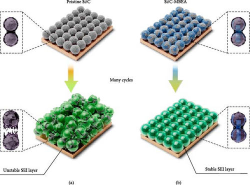
Figure 1 illustrates the advantages of the Si/C-MBEA electrode in terms of cycling performance. The SEI layer is formed on the surface of the pristine Si/C electrode during the initial lithiation. However, it could rupture owing to its insufficient mechanical stability associated with significant volume changes in Si during cycling (Figure 1a). Therefore, the bare Si surface is exposed to the electrolyte owing to the mechanically damaged SEI layer, resulting in drastic capacity decay with continuous SEI formation and an increase in overpotentials. In contrast, the Si/C-MBEA electrode could exhibit stable cycling performance with inorganically mitigated volume changes, as shown in Figure 1b. MBEA is beneficial for enhancing the binding affinity between the binder and Si/C to alleviate the volume changes in Si and stabilize the anode interface by facilitating the formation of a robust inorganic-rich SEI layer.
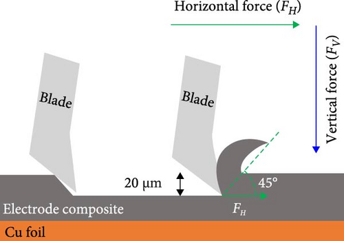
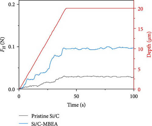
An ideal binder should provide strong binding affinity between the active materials, which can alleviate volume changes in the electrode and prevent electrode pulverization [35–37]. However, substantial volume changes in Si-based electrodes disrupt the binding affinity, resulting in the formation of microcracks, delamination of the active materials, and poor electrochemical performance. To investigate the binding affinity of the pristine Si/C and Si/C-MBEA electrodes, the electrode adhesion was analyzed with an SAICAS to an electrode depth of up to 20 µm. SAICAS utilizes a sharp cutting blade to measure the horizontal force (FH) and vertical force (FV) along the surface (Figure 2a) [38, 39]. These force variations provide decisive information on electrode adhesion, cohesion properties, and polymeric binder distribution within the electrode [40]. As shown in Figure 2b, the Si/C-MBEA exhibits a significantly higher adhesion strength than the pristine Si/C electrode (pristine Si/C = 34 N/m, Si/C-MBEA = 96 N/m). The outstanding electrode adhesion properties of the Si/C-MBEA originated from the strong binding affinity of PVP to Si owing to its polar functional groups. CMC and SBR binders have a higher binding affinity for PVP on the surface of Si/C than on pristine Si/C.
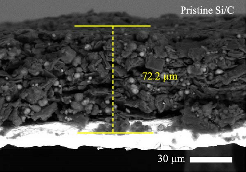
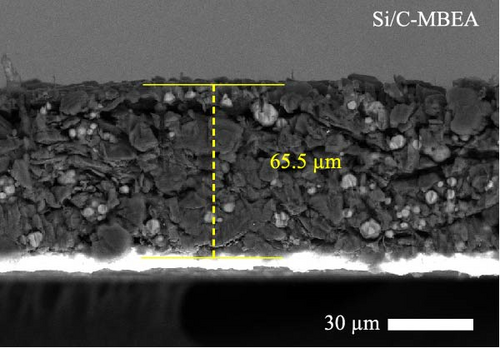
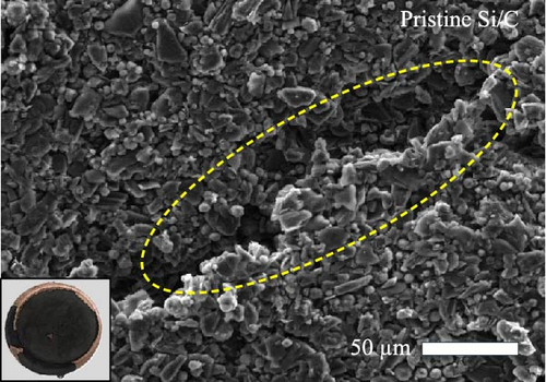

To investigate the electrode swelling behavior associated with the adhesion properties of the pristine Si/C and Si/C-MBEA electrodes, SEM images were obtained after 100 charge/discharge cycles (Figure 2c–f). Both electrodes were designed with the same active material loading and density, with an electrode thickness of approximately 47 μm before cycling (Figure S1a,b). However, the pristine Si/C and Si/C-MBEA electrodes exhibited considerably different electrode swelling behaviors after 100 cycles. The pristine Si/C electrode exhibited a severe electrode swelling ratio of 50.5% with an increased electrode thickness of 72.3 μm owing to the deteriorated binding affinity associated with substantial volume changes in Si (Figure 2c). In contrast, the Si/C-MBEA electrode demonstrated a relatively mitigated electrode swelling ratio of 38.5% with an electrode thickness of 66.5 μm (Figure 2d). This demonstrates that PVP contributes to the enhanced binding affinity of the electrode to buffer the volume changes in Si during cycling. The top-view SEM images further prove the advantages of the Si/C-MBEA electrode owing to its outstanding binding affinity. The surfaces of both electrodes exhibited similar morphology before cycling (Figure S1c,d). However, the pristine Si/C electrode exhibited severe microcracks associated with the volume changes in Si, which impeded efficient charge percolation and increased the overpotential (Figure 2e). In contrast, the Si/C-MBEA electrode exhibited homogeneously distributed particles without microcracks even after 100 cycles (Figure 2f). These results confirm that the Si/C-MBEA electrode exhibited highly reduced electrode swelling behavior with strong binding affinity during long-term cycling.
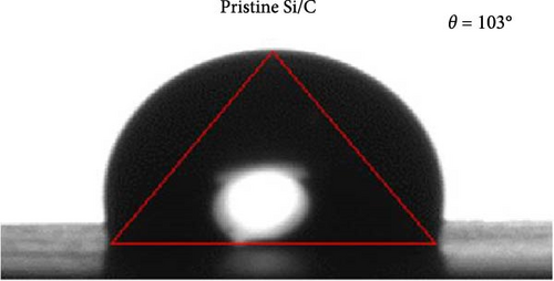
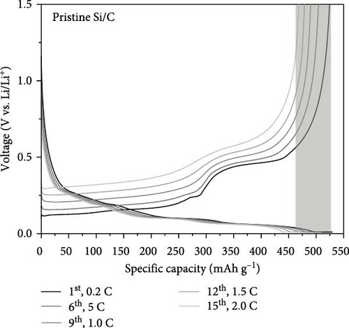
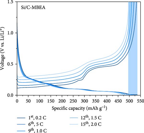
To determine the electrolyte wetting properties of the pristine Si/C and Si/C-MBEA electrodes, the contact angle was measured (Figure 3a,b). Electrolyte wettability is one of the most crucial parameters in the design of high-performance electrodes, which is closely related to fast Li-ion kinetics and overpotentials in high-energy-density LIBs [2, 41]. The pristine Si/C and Si/C-MBEA electrodes exhibited contact angles of 103° and 87°, respectively (Figure 3a, b). The lower contact angle value of the Si/C-MBEA electrode indicates that it has a higher affinity for polar electrolytes, which is attributed to the hydrophilic characteristics of PVP owing to its polar functional groups, such as amide and carbonyl groups. The excellent electrolyte wettability of the Si/C-MBEA electrode facilitates efficient charge transfer and reduces the electrode overpotential. To investigate the correlation between electrolyte wettability and the rate performance of the electrodes, the discharge (lithiation) rate of the pristine Si/C and Si/C-MBEA electrodes was fixed at 0.2 C, while the charge (delithiation) capacity was measured starting from 0.2 C and incrementally increased to 2.0 C every three cycles (Figure 3c,d). The pristine Si/C electrode exhibited an initial charge capacity of 524 mAh g−1 during the formation cycle at 0.2 C. However, at a rate of 2 C, the charge capacity decreased to 468 mAh g−1. In contrast, the Si/C-MBEA electrode exhibited enhanced rate performance. The initial charge capacity of the Si/C-MBEA electrode is equivalent to that of the pristine Si/C electrode, exhibiting a specific capacity of 532 mAh g−1 during the formation cycle. As the charge rate was increased to 2 C, the Si/C-MBEA electrode exhibited a specific capacity of 497 mAh g⁻1, showing enhanced rate capability compared to the pristine Si/C electrode. To evaluate Li-ion loss and stability under increased charging rates, the coulombic efficiency was analyzed, and it was confirmed that the Si/C-MBEA electrode exhibited a high average coulombic efficiency of approximately 99.2% (Figure S2). The results indicate that the pristine Si/C electrode has a significant capacity loss at high rates during cycling. However, the Si/C-MBEA electrode demonstrated an outstanding rate capability at a high C-rate owing to its enhanced electrolyte permeability and binding affinity.

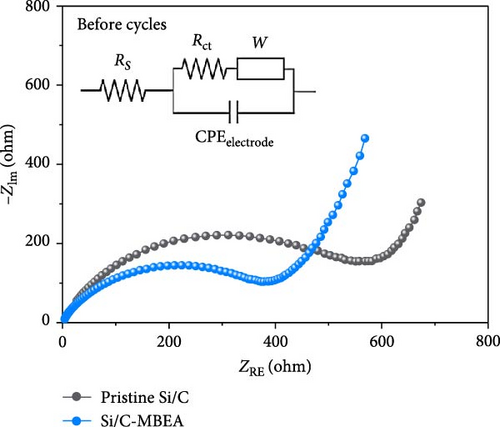
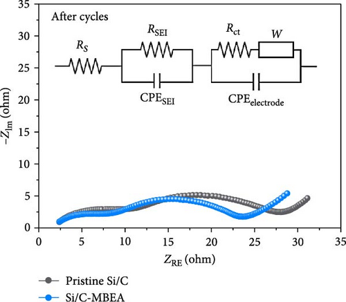

To understand the correlation between rate capability and electrochemical resistance of the pristine Si/C and Si/C-MBEA electrodes, EIS was observed in the frequency range of 250 kHz–10 mHz at an amplitude of 5 mV (Figure 3e,f). The first semicircle in the high-frequency region originates from the SEI resistance (RSEI), and the second semicircle corresponds to the charge transfer resistance (Rct) in the medium-frequency region [42–44]. The EIS results for the pristine Si/C and Si/C-MBEA electrodes before cycling are shown in Figure 3e. The Si/C-MBEA electrode exhibits lower impedance values than the pristine Si/C electrode before cycling. The excellent electrolyte wettability of the Si/C-MBEA electrode facilitated rapid Li-ion transport across the anode interface within the electrode, resulting in an enhanced rate capability with reduced interfacial resistance. After 10 cycles, the EIS analysis confirmed that the impedance changes in both the pristine Si/C and Si/C-MBEA electrodes were closely related to SEI formation (Figure 3f). The pristine Si/C electrode exhibited a higher RSEI of 9.1 Ω, while the Si/C-MBEA electrode showed a relatively lower RSEI of 5.9 Ω. This indicates that the Si/C-MBEA electrode formed a low-resistance SEI layer, facilitating rapid Li-ion transport across the anode interface. In addition, the Rct of the pristine Si/C and Si/C-MBEA electrodes was 20.1 and 15.3 Ω, respectively. The detailed resistance values are summarized in Figure 3g. These results demonstrate that PVP stabilizes the SEI layer with inorganic-rich compounds and enhances the electrolyte wettability, facilitating fast Li-ion transport across the anode interface with enhanced charge-transfer kinetics.
Generally, the SEI layer is composed of organic and inorganic species that are ionically conductive and electronically insulating [45–47]. An ideal SEI layer protects the electrode surface, prevents further electrolyte decomposition, and facilitates fast Li-ion transport [48]. However, the substantial volume expansion of Si causes the SEI layer to rupture and exposes the fresh Si surface to the electrolyte. Consequently, the SEI layer can accumulate during repetitive cycles, leading to increased electrode resistance, reduced Li-ion kinetics, and the loss of reversible Li ions. Therefore, a chemically stable and mechanically robust SEI layer must be formed for the Si/C composite anode to achieve stable cycling performance.
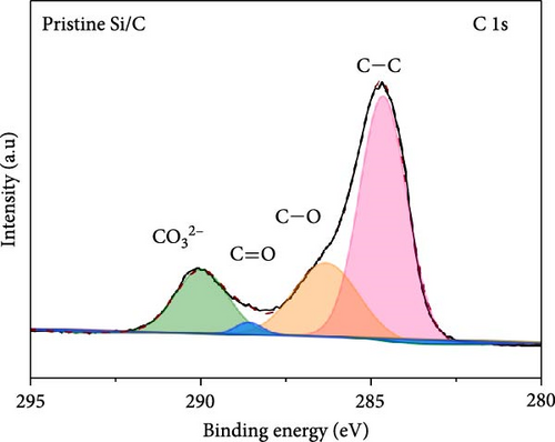
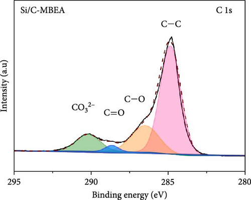
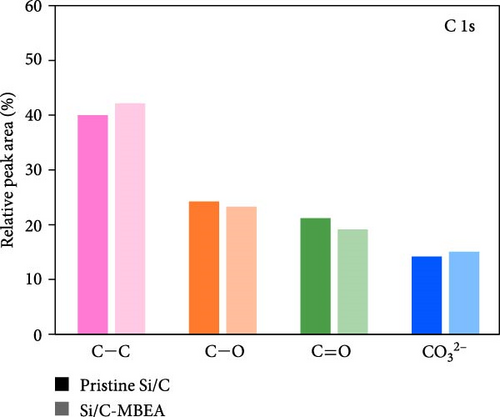
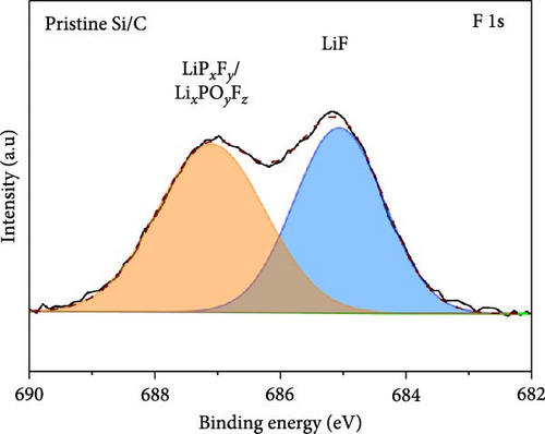
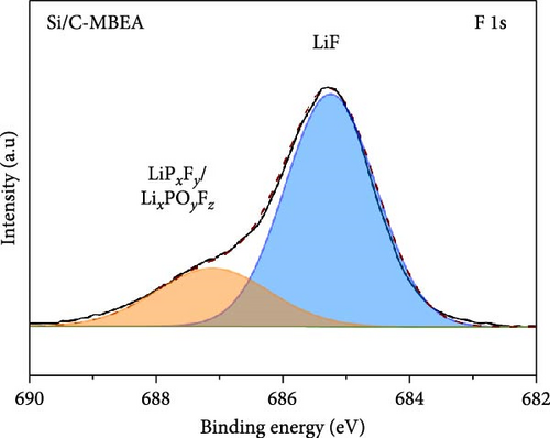
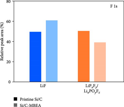
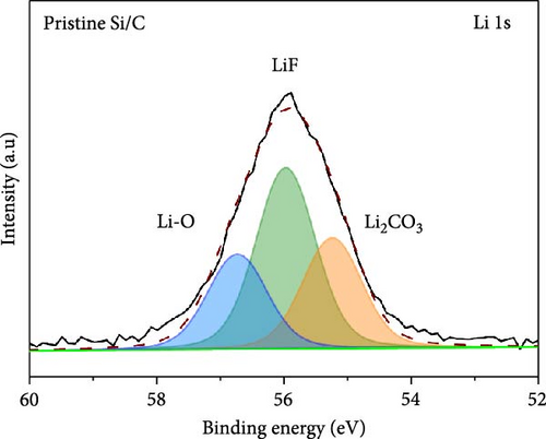
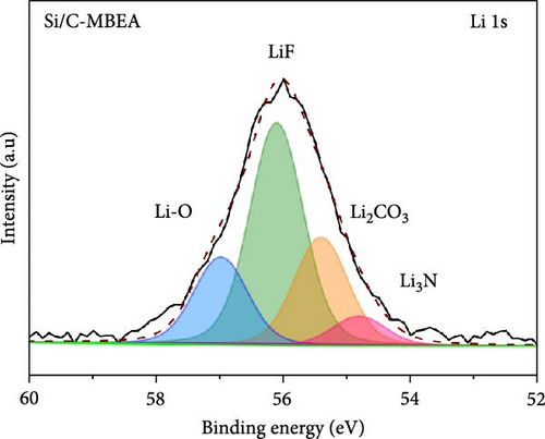
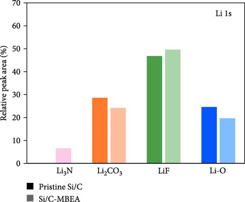
To investigate the SEI layer on the pristine Si/C and Si/C-MBEA electrodes, surface characterization was performed with XPS after the initial cycle in a half-cell test. Figure 4a,b shows the deconvoluted C 1s XPS spectra of the pristine Si/C and Si/C-MBEA electrodes, respectively. The C 1s spectrum was distinctly separated into four peaks corresponding to C─C (284.7 eV), C─O (286.3 eV), C═O (288.7 eV), and CO32– (290.0 eV); their relative peak areas are summarized in Figure 4c [49]. These compounds originate from solvents, such as EC, EMC, and DEC, which have lower lowest unoccupied molecular orbital (LUMO) energies than Li salts [50]. The pristine Si/C and Si/C-MBEA electrodes exhibited no significant differences in the SEI components associated with solvent decomposition. Interestingly, the deconvoluted F 1s XPS spectrum exhibited a clear difference between the inorganic SEI layers of the pristine Si/C and Si/C-MBEA electrodes. The F 1s spectrum was differentiated into two peaks corresponding to Li–F (685.0 eV) and LiPxFy/LixPOyFz (687.1 eV), as shown in Figure 4d,e [51, 52]. The relative peak areas are presented in Figure 4f. The LiPxFy/LixPOyFz compounds are attributed to the decomposition of the LiPF6 salt, and LiF primarily originates from the decomposition of FEC. LiF is one of the most important SEI components because of its high mechanical strength, low Li diffusion barrier energy, and high thermodynamic stability [53]. The Si/C-MBEA electrode showed a relatively higher peak area for LiF than the LiPxFy/LixPOyFz compounds, compared to the pristine Si/C electrode counterpart. PVP, composed of vinylpyrrolidone (VP) units in its polymer backbone, possesses a relatively low LUMO energy level compared to that of the electrolyte components [54, 55]. This makes PVP itself susceptible to electrochemical reduction during the initial SEI formation, along with VC and FEC. The decomposition products of PVP are believed to interact with those of FEC or LiPF6, thereby inducing the formation of a LiF-rich SEI layer. Additionally, Figure 4g,h shows the deconvoluted Li 1s XPS spectrum, where the pristine Si/C electrode is distinguished by LiF (56.0 eV), Li2CO3 (55.3 eV), and LiO (56.5 eV). Interestingly, the Li3N (54.88 eV) peak can only be observed in the Si/C-MBEA electrode, which originates from the nitrogen source of PVP [31, 56]. The relative peak areas of these components are shown in Figure 4i. To further elucidate the origin of Li3N, a comparative evaluation was conducted using a control electrode without active material. The N 1s XPS spectrum showed distinct peaks corresponding to Li3N and LiOxNy only in the control electrode with PVP (Figure S3). This result demonstrates that PVP functions as an electrochemically active species capable of forming nitrogen-containing SEI components. Additionally, as shown in Figure S4, CV analysis was conducted to examine SEI decomposition. PVP has a LUMO level similar to DEC and EMC, allowing reduction reactions during initial lithiation in a comparable potential range [54]. In the 0.3–0.7 V range, the control electrode without PVP showed a distinct reduction peak due to electrolyte decomposition, which may cause irreversible capacity loss [55, 57]. In contrast, the control electrode with PVP showed suppressed side reactions. The predominant SEI layer, consisting of Li3N and LiF, not only enhances the interfacial stability between the electrode and electrolyte but also facilitates Li-ion kinetics [29, 58]. These results demonstrate that the Si/C-MBEA electrode has a stable and robust inorganic-rich SEI layer that facilitates fast Li-ion transport and shields the anode surface from additional electrolyte decomposition.
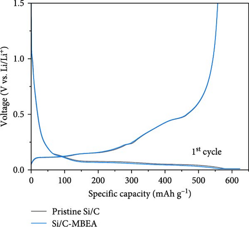
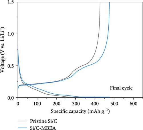
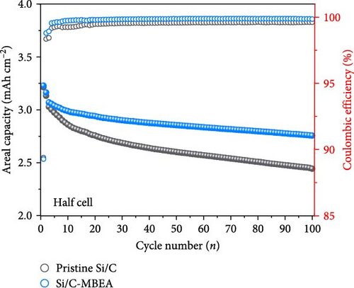
To evaluate the electrochemical performance of the pristine Si/C and Si/C-MBEA electrodes, galvanostatic charge/discharge measurements were conducted using a half-cell test. The initial cycle of all half cells was examined at a rate of 0.1 C (1 C = 3.0 mA cm−2), followed by 100 cycles at a rate of 0.5 C. Figure 5a,b shows the charge and discharge voltage profiles of the pristine Si/C and Si/C-MBEA electrodes. In the first cycle, the pristine Si/C and Si/C-MBEA electrodes exhibited similar voltage profiles, with specific charge capacities of 623.5 and 624.7 mAh g−1, respectively, and discharge capacities of 557.3 and 557.6 mAh g−1, respectively. However, the pristine Si/C electrode showed a significant reduction in charge capacity to 428.8 mAh g−1 after 100 cycles. In contrast, the Si/C-MBEA electrode exhibited more stable cycling performance, demonstrating a charge capacity of 476.7 mAh g−1 after 100 cycles. The formation of the SEI layer and the electrochemical reactions are further illustrated by the differential capacity (dQ/dV) plots in the initial cycle (Figure S5). In the initial cycles, a peak associated with the reductive decomposition of the FEC electrolyte was evident. Upon the addition of PVP, an enhancement in the intensity of these peaks was observed, indicating the formation of an inorganic-rich SEI layer. This suggests that PVP facilitated the formation of a robust and stable SEI layer by promoting the generation of inorganic materials with high ionic conductivity and stability. The increased peak intensity observed in the dQ/dV plots confirms the influence of PVP on the SEI composition, leading to improved electrochemical performance and enhanced electrode stability during cycling. These results demonstrate that the Si/C-MBEA electrode exhibits outstanding cycling performance compared to the pristine Si/C electrode. Moreover, as shown in Figures 5c and S6, the pristine Si/C electrode exhibited drastic capacity decay with a capacity retention of 81.2% after 100 cycles, whereas the Si/C-MBEA electrode showed stable cycling capacity with a capacity retention of 89.6%. The enhanced cycle life and improved coulombic efficiency observed for the Si/C-MBEA electrode can be attributed to the advantages of PVP in the formation of a stable SEI layer, enhanced electrolyte wettability, and excellent binding affinity. In this regard, the Si/C-MBEA electrode enabled fast and homogeneous electrochemical reactions with mitigated volume changes during cycling.
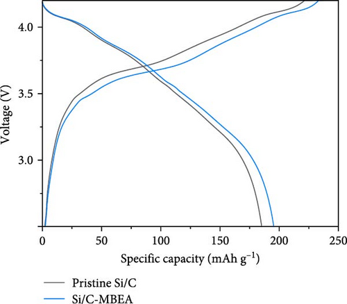
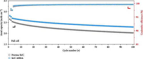
To demonstrate the practical implementation of the Si/C-MBEA, electrochemical full cells were evaluated using NCM811 as the cathode with an N/P ratio of 1:1. The full cells prepared with pristine Si/C and Si/C-MBEA electrodes showed clear differences in their electrochemical properties. In the first charge/discharge cycle at 0.1 C, the cell prepared with the Si/C-MBEA electrode exhibited a specific capacity of 195.4 mAh g−1. However, the cell with the pristine Si/C electrode showed a relatively lower specific capacity of 185.2 mAh g−1 (Figure 5d). In addition, the cell prepared with the Si/C-MBEA electrode exhibited an average coulombic efficiency of 99.35% during cycling (Figure 5e). The higher specific capacity and coulombic efficiency of the Si/C-MBEA electrode originated from the SEI stabilization effect of PVP. Furthermore, the full cell incorporating the Si/C-MBEA electrode demonstrated a high areal capacity of 2.8 mAh cm−2, highlighting its potential for practical application in high-performance energy storage systems. The cycling performance of full cells was evaluated at 0.5 C (1 C = 2.7 mA cm−2) in the voltage range of 2.8–4.25 V. Moreover, as shown in Figure S7, the full cell prepared with the Si/C-MBEA electrode exhibited a higher capacity retention (83.5%) than the pristine Si/C electrode (79.3%) after 100 cycles. These results strongly suggest that PVP could serve as an effective additive in full cell applications.
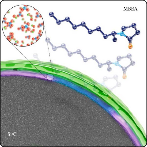
The detailed mechanism that enhanced the electrochemical performance and stability of the Si/C-MBEA electrode is summarized in Figure 6. (1) The MBEA promotes the formation of LiF and Li3N-rich inorganic SEI layer with high chemical stability and mechanical integrity. This stable SEI layer can facilitate fast charge transfer kinetics without mechanochemical degradation during cycling. (2) The hydrophilic nature of MBEA on the Si/C surface can enhance the binding affinity between active particles, resulting in enhanced adhesion and cohesion properties during repetitive cycling. Therefore, MBEA plays a crucial role in stabilizing the SEI layer and mitigating the mechanical stress caused by the repeated expansion of Si particles, leading to the outstanding cycling performance for high-energy-density Si/C anodes.
4. Conclusion
In this study, we propose a facile and effective electrode engineering strategy to enhance the electrochemical performance of Si/C composite anodes in high-energy-density LIBs. An MBEA was incorporated into the Si/C composite electrode to stabilize the anode interface and mitigate the volume changes of Si. The MBEA plays a crucial role in the Si/C-MBEA electrode: (1) forms a robust inorganic-rich SEI layer; (2) enhances binding affinity owing to its polar functional groups; (3) facilitates Li-ion transport with rapid electrolyte wettability; and (4) mitigates volume changes. Therefore, the Si/C-MBEA electrode exhibited outstanding cycling performance and rate capability with alleviated volume changes in Si. EIS and galvanostatic charge/discharge evaluations revealed that the Si/C-MBEA electrode exhibited lower RSEI and Rct values and excellent electrochemical properties. Furthermore, full cell evaluations demonstrated the practical use of the Si/C-MBEA electrode with high areal capacity. This study addresses the challenges of Si anodes experiencing substantial volume changes, resulting in poor electrochemical performance, and paves the way for the development of reliable and high-performance LIBs.
Conflicts of Interest
The authors declare no conflicts of interest.
Author Contributions
Dongsoo Lee: writing – original draft, conceptualization, data curation. Woojin Jeong: writing – original draft, formal analysis, investigation. Juhyun Lee: investigation, writing–original draft. Hee Eun Yoo: investigation, writing – original draft. Seho Sun: data curation. Chanho Lee: visualization. Jinhyung Kim: visualization. Yongil Kim: methodology. Moonsu Yoon: data curation. Patrick Joohyun Kim: validation. Ungyu Paik: methodology, visualization. Jung Woo Lee: visualization, data curation. Taeseup Song: supervision, writing – review and editing. Junghyun Choi: supervision, writing – review and editing. Dongsoo Lee, Woojin Jeong, Juhyun Lee, and Hee Eun Yoo contributed equally to this work.
Funding
This research was supported by the National R&D Program through the National Research Foundation of Korea (NRF), funded by the Ministry of Science and ICT (Grant RS-2024-00408156) and the National Research Council of Science & Technology (NST) grant by the Korea Government (MSIT) (Grant GTL24011-000).
Acknowledgments
This research was supported by the National R&D Program through the National Research Foundation of Korea (NRF), funded by the Ministry of Science and ICT (Grant RS-2024-00408156) and the National Research Council of Science & Technology (NST) grant by the Korea Government (MSIT) (Grant GTL24011-000).
Supporting Information
Additional supporting information can be found online in the Supporting Information section.
Open Research
Data Availability Statement
The data supporting the findings of this study are available in the supporting information of this article.


