Lidar-Binocular Camera-Integrated Navigation System for Underground Parking
Abstract
It is well known that vehicles highly rely on satellite navigation in an open intelligent traffic environment. However, satellite navigation cannot obtain accurate positioning information for vehicles in the interior of underground garage, as they comprise a semienclosed navigation space, worse light than outdoors in a special traffic environment. To address this problem in this research, the Lidar-binocular camera-integrated navigation system (LBCINS) is established for underground parking indoor environment. The obtained Lidar data from the simulation experiment are preprocessed, and the matching results of the inertial navigation system (INS) under the normal distributions transform (NDT) algorithm and the iterative closest point (ICP) algorithm are compared. The simulation experiment results show that in the complex underground parking environment, the INS under Lidar-NDT algorithm with binocular camera achieves a better performance. Then, in the field experiment, the 3D cloud point data were collected by the test vehicle that equipped with the proposed navigation system from an underground parking and obtained 199 pairs of feature points’ distances. Finally, four different statistical methods were used to analyze the calculated distance errors. Results show that under different error statistical methods, the distance error values of the proposed navigation system are 0.00901, 0.059, 0.00766, and 0.087 m, respectively which present a much higher precision than 5.0 m in the specification requested for inertial-integrated navigation terminal.
1. Introduction
With the development of cities, a sharp increase of private cars ownership makes parking difficulties increasing prominent. Research data show that car ownership in China had reached 217 million. However, the ratio of private cars to parking lots is about 1:0.8 in large cities, only about 1:0.5 in small and medium cities [1]. That means there is still an insufficiency of more than 50 million car parking lots in China. Limited by the shortage of ground space resources, therefore accelerating the construction of underground parking lots has also become a significant part of the plan in urban areas. However, due to the poor signal penetration capability of satellites, worse light than outdoors makes it difficult to get a high precision positioning and navigation at indoor environments. Also, indoor positioning data cannot be acquired correctly, which make underground parking position and navigation become a special case.
In recent years, the intelligent transportation has got a vigorous development, for large cities have a lot of researchers paying their attention on shared autonomous vehicles to relieve the pressure of urban traffic and parking problems [2]. Also, the impact of automated vehicles on traffic assignment, mode split, traffic risk evaluation and parking behavior also get more and more attentions [3]. Meanwhile, artificial intelligence (AI) becomes a clear development trend in a lot of industries. AI technology can help make many fields achieve “unmanned” operation, reducing labor costs and improving system operation safety and efficiency [4–6]. Underground parking is a vertical field of the international union (ITU) industry that combined computer vision (CV), automatic number plate recognition (ANPR), and intelligent camera technology and gradually evolving into an “unmanned” operation form [7, 8]. Jiang et al. based on ultra-wideband (UWB) technique proposed a three-stage practical and economical layout planning approach for UWB base stations, considering regional differentiation accuracy requirements for automated valet parking in an indoor environment [9]. Vision-Zenit released a series of binocular smart cameras, which is an innovative system that employs a high-accuracy recognition and localization approach, utilizing a heterogeneous dual lens to establish binocular stereo vision, extract depth information from the scene, and facilitate three-dimensional (3D) vehicle modeling [10].
According to a study on light detection and ranging (Lidar) in navigation systems, the National Aeronautics and Space Administration (NASA) has successfully developed airborne marine Lidar with scanning and high-velocity data recording capabilities. Bathymetric surveys were performed in Chesapeake Bay and the Atlantic Ocean, and the seafloor topography was drawn where the water depth was less than 10 m [11]. Therefore, the enormous application potential contained in airborne Lidar began to attract attention and was soon applied to land terrain measurement [12]. The big progress got in Global Positioning System (GPS) and inertial navigation systems (INSs) recent years has made it possible to locate and determine attitudes accurately and instantaneously during laser scanning [13]. Regarding research on integrated navigation, Wu et al. studied the map mapping (MM), dead reckoning (DR), INSs, and GPS-integrated navigation methods. They also found that the purpose of integrated navigation was to reduce costs, improve navigation accuracy, enhance reliability, and develop digital navigation [14].
Li et al. based on the integrated navigation of the GPS and the Micro–Electro–Mechanical System (MEMS) inertial navigation system to solved the problem of switching navigation algorithms in the entrance and exit of underground parking lots and proposed a low-cost vehicular seamless navigation technology based on the reduced inertial sensor system (RISS)/GPS between the outdoors and an underground garage [15]. Li et al. used Lidar and INS for indoor combination to realize unmanned aerial vehicle (UAV) positioning technology under technology fusion [16]. Fu et al. detected vehicle motion through the INS and sensed the surrounding environment through Lidar and millimeter wave radar, both of which were combined to achieve the automatic localization of driverless cars on the road [17]. Azurmendi proposed a simultaneous object-detection and distance-estimation algorithm based on YOLOv5 for obstacle detection in indoor autonomous vehicles [18]. Liu et al. explored the performance of INS and global navigation satellite system (GNSS) and found that the processor computing performance of the integration of INS/GNSS is lower, while the processor performance of the INS model of the graph optimization fusion algorithm is better [19]. For the Lidar application field, Kim et al. investigated different Lidar methods in terms of light source, ranging, and imaging. They found that a 905 nm light source had a low cost and was relatively mature [20]. Liu et al. used a 16-channel Lidar to help the visual system build an accurate semantic map and proposed an AVP-SLAM solution for underground parking lot [21].
The development of autonomous cameras and image processing technology has greatly promoted visual navigation technology. Visual navigation is an emerging navigation method that uses charge-coupled device (CCD) cameras to capture road images and adopts machine vision and other related technologies to identify paths and realize automatic navigation. Visual navigation is currently a new technology. It captures images of the surrounding environment through cameras, filters and calculates the images, completes its attitude determination and path recognition, and makes navigation decisions [22]. Because visual navigation usually adopts a passive working mode, simple equipment, low cost, good economy, wide application range, and theoretically the best guidance flexibility, it has developed very rapidly in recent years. It does not rely on any external equipment and only needs to calculate the information in the storage system and the environment to obtain navigation information. Luque-Vega realized autonomous intelligent identification and navigation of intelligent vehicles based on an intelligent vehicle system and utilized visual navigation technology [23].
However, the studies on Lidar sensor navigation systems about underground parking are most focus on autonomous driving and intelligent robots. With the development of Internet of Things technology, intelligent transportation and intelligent travel have attracted increasing attention from the public. Through independent innovation and technology research and development, “electronic parking fees and management, real-time intelligent update of parking information, and maximum utilization of parking space resources” will be the research hot point focus on parking problems.
- 1.
Compared with ground traffic scenarios, underground parking lots are more challenging to localize due to enclosed environments and GNSS failure. Existing localization methods for underground parking lots require additional devices such as WIFI or UWB with unstable localization. A robust vision-based localization method to all carpark signs in underground parking lots is necessary.
- 2.
A high-precision localization based on feature matching is critical. However, current methods still suffer from feature extraction problems due to low efficiency and instability. Also, high repetition and complex conditions of underground parking lots exacerbate the difficulty of feature matching, the affect, the accuracy, and robustness of localization. A new visual feature for indoor scenarios must be proposed.
- 1.
An Lidar-binocular camera-integrated navigation system (LBCINS) for underground parking is designed by integrating Lidar-binocular camera. We introduced the characteristics and functions of the Intelligent Sensor Networks (ISNs) and analyzed the application of light detection and ranging (Lidar) in automatic navigation. The combination of Lidar and binocular cameras enables vehicle navigation and obstacle recognition in underground parking to address the high costs of current methods that require additional auxiliary equipment and markers. Low-cost, high-precision localization is realized by using Binocular Camera-based sensors.
- 2.
A theoretical basis is proposed for exploring Lidar-binocular camera on INS. The LBCINS is formed by fusing Lidar and a binocular camera. Finally, the LBCINS performance under the light detection and ranging-normal distributions transform (NDT) algorithm is analyzed to address the instability of current features. The method has good matching stability and strong robustness to cope with the changing of illumination in underground parking scenario.
The rest of this paper is organized as follows. Section 2 describes the LBCINS. Section 3 describes experimental environment and settings. The experimental results of the proposed methods are shown in Section 4, followed by discussion and conclusions in Section 5.
2. Materials
2.1. Application of ISN Technology in the Underground Parking
Sensors are a significant part of modern information technology. Traditionally, sensor output is mostly an analog signal without signal processing and networking functions. They should be connected to specific measuring instruments to perform transmission functions and signal processing. Intelligent sensors can process raw data internally, exchange data with the outside world through standard interfaces, and change the way the sensor works through software control according to actual demands, achieving intelligence and networking. Because the standard bus interface is adopted, the intelligent sensor has good openness and scalability, which brings much expansion space for the system [24].
The ISN is composed of sensors, microprocessors, and related electrical circuits shown as Figure 1.
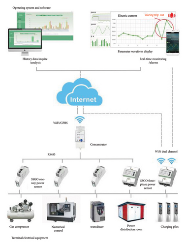
The sensor converts the measured chemical or physical quantities into corresponding electrical signals and then sends them to signal modulation circuit, which is filtered, amplified, and analog-to-digital (A/D) converter, and the microprocessor. The microprocessor calculates, stores, and analyzes the received signal through the feedback loop; it adjusts the sensor and signal conditioning circuit to regulate and control the measurement process, meanwhile transmits the processing results to the output interface. After being processed by the interface circuit, the digitized measurement results are output based on the output format and interface customization. The microprocessor is the core of the smart sensor because it fully utilizes various software functions, makes the sensor intelligent, and greatly improves the corresponding performance [25]. The ISN features are exhibited in Table 1.
| Characteristics | Channel of realization |
|---|---|
| High precision | Automatic zeroing to eliminate accidental errors |
| High reliability and high stability | Automatic compensation for drift of system characteristics for emergency handling of abnormal situations |
| High signal-to-noise ratio (SNR) and high resolution | Correlation analysis and processing such as digital filtering eliminates cross-sensitivity in multiparameter state |
| Good adaptability | Operated in an optimal low-power mode to adapt to different environments and improve transmission efficiency |
| Higher cost performance | Microprocessor/microcomputer combination, implemented using inexpensive integrated circuit technology and chips and powerful software |
The function of the intelligent sensor is designed by simulating the coordinated actions of the human brain and senses, combined with long-term research of testing technology and practical experience. It is an independent intelligent unit, which reduces the stringent requirements on the original hardware performance. Due to the software, the sensor performance is greatly improved [26]. The main functions of the intelligent sensor are demonstrated in Figure 2.
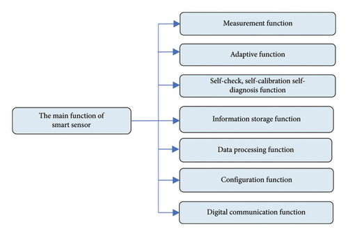
In Figure 2, the intelligent sensor functions include seven aspects. Various physical and chemical quantities can be measured by the composite sensitive function and information that more fully reflects the laws of motion of matter can be provided. The adaptive function extends the life of the device. It also automatically adapts to various environmental conditions, thus expanding the field of work. Adaptive technology improves sensor repeatability and accuracy. The self-diagnostic function performs a self-test at power-on, and this is a diagnostic test to determine if a component is faulty. Moreover, online calibration can be performed through the usage time, and the microprocessor adopts the measured characteristic data stored in electrically erasable programmable read-only memory (E2PROM) for comparison and calibration. Intelligent sensors store a large amount of information that users can inquire about at any moment. The data processing function amplifies and digitizes the signal and then implements signal conditioning in the software. The configuration function can choose the requirements at will according to the needs and can be used for different tasks or applications depending on the scenario. The intelligent sensor has a microcontroller, so digital serial communication can be configured naturally via an external connection.
To apply ISN to underground parking navigation systems, a large number of intelligent sensor nodes are randomly scattered in the target monitoring area. Network topology planning is carried out on the ISN. During the data collection process, the effective data collected by each smart sensor need to be sent back to each monitoring node and base station in a timely and accurate manner. The intelligent sensor node collects a large quantity of real-time data for compression processing. The system provides total number of occupied parking spaces in parking lot and more specific area information. Intelligent sensors are placed at the entrances, exits, and zone transitions of each underground parking area. Sensors at the entrances and exits wirelessly transmit vehicle data from these two locations to a central base station at the entrances and exits. Sensor nodes monitoring zone transition points detect traffic flow and direction and determine if vehicles are moving between zones and send data to a central base station, which analyzes all incoming data and provides real-time total available parking spaces in the underground parking spaces and the number of parking spaces in each area.
With the descriptions above, the ISN applied to underground parking is mainly able to implement three functions. The intelligent sensor nodes installed in the parking lot can sense whether there is a car parked in the corresponding parking space and send the data back to the central system. Through ISN, it is convenient for the entire underground parking area to automatically count the number and location of free parking spaces. The wireless transmission nodes distributed in the underground parking guide the vehicle to enter the free parking space and display the running status of the nearby vehicles at any time, avoiding the occurrence of accidents such as scratches. Integrating the ISN and radio frequency identification (RFID) technology can intelligently sense the stay time of vehicles in the parking lot through sensor nodes and only set charging nodes at the exit to realize nonstop charging.
2.2. The Composition and Working Principle of Lidar
Based on the ISN function, Lidar has been widely used in automatic navigation. Lidar is an all-in-one system of lasers, GPS, and IMU to gain point cloud data and produce precise digital 3D models. The combination of these three techniques can acquire the surrounding 3D reality with consistent absolute measurement point positions [27]. The working principle of Lidar is indicated in Figure 3.
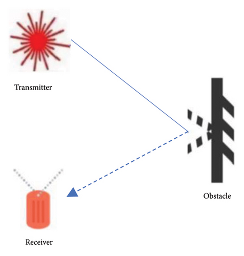
Figure 3 shows that Lidar uses a pulsed laser to measure distance. Lidar fires a laser beam and calculates the distance from the Lidar to the target point. Data points are formed by measuring how long it takes for light to hit an object or surface and bounce back. Millions of data points may be acquired in the process, which is called a “point cloud.” By processing these data, accurate 3D stereoscopic images are presented in seconds. Since the speed of light is known, the distance between the laser and the measured object can be calculated by the difference between the time when the laser beam is emitted and the backscattered light is received, which similar to radar, transmitting system sends out signals, which are collected by the receiving system after being reflected by the target. The distance to the target is defined by measuring the propagation time of the reflected light [28].
Integrated navigation uses multiple sensors to navigate and locate. Its essence is the information fusion of multiple sensors. Due to the difference in reference datum, the information of each sensor needs to complete the coordinate transformation on the basis of time synchronization and space alignment. The INS in the system performs state estimation to obtain the final navigation parameters. Lidar calculates the 3D coordinates of the target point by measuring the position and attitude of the target point relative to the laser scanning center and then colorizes and texturizes the point cloud according to the mapping relationship between the photo and the object. The reconstructed 3D surface shape of the object is attached to the inherent color texture of the object to make it realistic [29].
2.3. Application of the Binocular Camera in the Navigation System
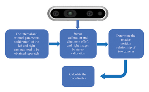
During binocular positioning process, the two cameras are on the same plane, and the optical axes are parallel to each other, similar to a person’s two eyes. For a feature point on the object, two cameras fixed at different positions are used to take images of the object, and the coordinates of the point on the image planes of the two cameras are obtained. As long as the precise relative positions of the two cameras are known, the coordinates of the feature points in the fixed coordinate system of one camera can be obtained by geometric methods; that is, the feature point positions can be determined [30]. Figure 4 depicts the binocular-positioning process.
-
Step 1: obtain and calibrate the internal and external parameters of the left and right cameras.
-
Step 2: calibrate and align the left and right images through the stereo coordinates.
-
Step 3: determine the relative positional relationship between the two cameras.
-
Step 4: calculate coordinates.
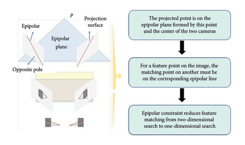
The positioning system of the binocular vision image is developed by Micro vision (3D vision image), which is used to identify and locate the chip position during the chip-linking process to better cure the chip in the desired position. The two cameras are positioned at the same point S on the image to match the points of the left and right pictures, which involves the binocular correction action. If the point feature on one image is used to match the corresponding point in another 2D image space, this process can be very time consuming [31]. To reduce the computational complexity of the matching search, limit constraints are employed to decrease the matching of corresponding points from a 2D search space to a one-dimensional search space. Figure 4 denotes the limit constraint principle.
3. Methodology
The point cloud data were obtained from testing site under the normal working state of the system and extract the coordinate values of feature points from point cloud data. The system detection environment of this experiment is in Windows 10. Also, the control network is arranged in the selected control field by using GPS static observation to avoid the binocular camera obtaining the high-precision 3D coordinate value of the feature point as the real value of the feature point in the test. This process was completed before the experiment.
3.1. Mechanism Design for LBCINS
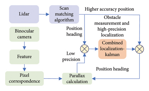
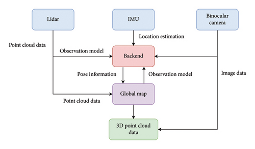
Integrated navigation needs multiple sensors to navigate and locate objects, and the core of the system is the information fusion of multiple sensors on the carrier. However, according to the different reference benchmarks of underground parking, the sensor needs to complete the information interaction and coordinate change synchronously in time and space. The LBCINS estimates the situation at the same time and space, then obtains the parameters required for the final navigation. The integrated navigation process of the Lidar-binocular camera is shown in Figure 6.
3.2. Parameters of LBCINS
The input fusion and conditional cost volume normalization (CCVNorm) of Lidar information are tightly integrated with the CCV components commonly used in stereo matching neural networks for binocular cameras. The stereo matching channel of the binocular camera extracts two-dimensional features, obtains the pixel correspondence, and performs the final disparity calculation. In the cost regularization stage of stereo matching, CCVNorm replaces the batch normalization layer and modulates the characteristic quantity of CCV conditioned on the Lidar data. By using these two proposed techniques, the disparity computation stage produces highly accurate disparity estimates.
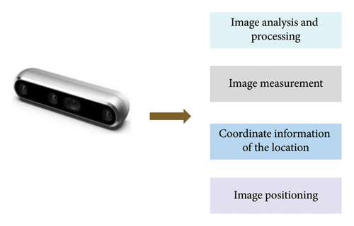
The positioning system of the binocular camera adopts two Microvision MV-808H cameras, a VS-M1024 continuous zoom lens, and an MV-8002 two-way high-definition image acquisition card to capture images simultaneously. The spot welding position of the chip is for accurate positioning when installing. The binocular vision inspection system accurately obtains the coordinate information of the installation or processing position on the circuit board through image analysis, processing, and image measurement, calculates the position coordinates, and provides the operation control of the manipulator. The hardware configuration of the binocular camera positioning is as follows. Camera: VS-808HC color high-definition camera, 520 lines, 1/3″ Sony CCD; resolution: 752∗582. HD frame grabber: MV-8002, which supports secondary development and multiple operating systems. Continuous magnifier: VS-M1024; high brightness ring light emitting diode (LED) for machine vision light source: VS-RL100R, and its advantages are adjustable brightness, low temperature, balanced, no flicker, no shadow, and long service life. IMU: WHEELTEC N300, with redundant sensor technology, three gyroscopes with zero-bias stability of 2°/h are fused to achieve higher 3D angle measurement accuracy and contains two independent sets of three-axis gyroscope, three-axis accelerometer, three-axis magnetometer and thermometer, belonging to the 12-axis attitude sensor series.
Binocular vision alignment system software includes Micro vision, one video cable, one trigger plug, and one camera support rod. The image extraction process of the LBCINS is outlined in Figure 7.
4. Experiment
4.1. Simulation Experiment
4.1.1. Analysis of the Preprocessing Results of Lidar Data
Before deploying the field experiment in true environment, we design the simulation environment to preliminary explore the performance of the proposed LBCINS. A great feature of the robot-operating system (ROS) is that it has a large number of useful components and tools. In this research, we introduced the Gazebo, a 3D dynamic simulator with the ability to accurately and efficiently simulate populations of robots in complex indoor and outdoor environments. Similar to game engines, Gazebo offers physics simulation at a much higher degree of fidelity, a suite of sensors, and interfaces for both users and programs.
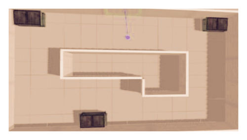
The simulation environment of integrated Lidar-binocular camera navigation is constructed as shown in Figure 8, which is a closed rectangular annular corridor space with three cubic obstacles distributed. The constructed moving object has dynamic characteristics, and the Lidar carries can output obstacle information in the simulated environment in real time. Figure 8 presents a simulation environment for LBCINS.
In this experiment, the order p of the filtering polynomial is set as 3, M = 30, and the collected data are preprocessed by Lidar data. Figure 9 exhibits the Lidar data preprocessing effect.
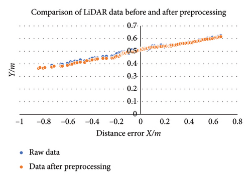
Figure 9 illustrates the Lidar data outcome of the targeted obstacle moving trajectory distance error before and after preprocessing. Compared with the processed data, the raw data show a bigger scatter than processed ones, which cannot show the complete real state of the obstacle target. After preprocessing, the degree of data scatter changes, the data noise is reduced, and closer to a straight line, which can better reflect the real state of the complete targeted obstacle. Therefore, the Lidar data-preprocessing process proposed by this research is effective.
4.1.2. Performance Analysis of LBCINS Under the Lidar-NDT Algorithm
To explore the performance of LBCINS under the Lidar-NDT algorithm, the distance error matching results as shown in Figure 10, and the pixel conversion heading angle of the obstacle target matched under the NDT algorithm as shown in Figure 11.
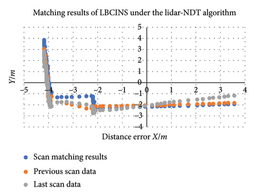

From Figure 10, we can see that the scan matching results of the NDT algorithm is overall in line with the previous scan data and the last scan data. Besides, along with the targeted obstacle moving the scan matching result of the algorithm and the previous scan data are getting closer, which indicate that the matching result of the LBCINS under the NDT algorithm is feasible. In Figure 11, we can see that the actual value and calculated value of pixel heading angle is 12.43 and 12.51, respectively, and the actual value and calculated value of distance are 0.307 and 0.144. The absolute value of error is 0.08 and 0.163, respectively, which are smaller than the integrated navigation accuracy requirements in the specification for BDS/MEMS inertial-integrated navigation terminal, that is, the minimum distance error is no more than 5 m and the minimum heading error is no more than 1.5°, which illustrate that the matching calculation result of the NDT algorithm can meet the requirements of the combined calculation in the LBCINS.
To further verify the LBCINS performance under the Lidar-NDT algorithm, the NDT algorithm is being compared with the iterative closest point (ICP) algorithm in terms of navigation performance in different environmental conditions. The LBCINS performance of underground parking is analyzed in three scenes. The LBCINS performance under the NDT algorithm is shown in Figure 12. The LBCINS performance under the ICP algorithm is displayed in Figure 13.
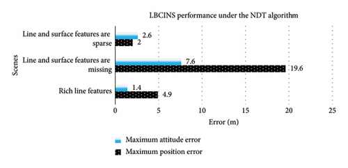
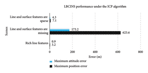
As shown in the Figures 12 and 13, both the LBCINS under the NDT and ICP algorithms present largest errors in the navigation position and attitude when the line and surface features are missing and the errors are smaller when in the scenes of rich and sparse features. This means that in the case of the existence of targeted obstacle characteristics in underground parking, the navigation system performance can achieve a more accurate navigation direction in the navigation position and attitude. However, the integrated navigation under the ICP algorithm presents bigger errors in scenes where line and surface features are sparse or missing, especially in the scenes where line and surface features are missing. The LBCINS under the NDT algorithm performs better than LBCINS under the ICP algorithm.
4.2. Field Experiment
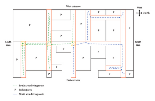
In the field experiment, cloud point data were collected from an underground parking divided into south and north areas. The test vehicle was designed to enter this underground parking from west entrance following the green arrow route to collect the data at south area and then enter from east entrance following the blue arrow route to collect the data at north area. The yellow boxes represent the no-parking signs. The test vehicle data collection route is shown in Figure 14.
4.2.1. Cloud Point Data Collection
The test vehicle, mainly data collection equipment, is shown in Figure 15. These equipment include power supply unit, miniPC with AMD R9 5900HX and 32 GB RAM, WHEELTEC N300 Inertial measurement unit (IMU), an Intel RealSense Depth Camera D455 camera, three imx355 industrial vision cameras, Robosense Helios-16 lidar, and G200mini integrated navigation system. The view field of D455 camera is 86° in horizontal and 57° in vertical. The field view of Robosense Helios 16 is 360° in horizontal and 30° (−15°∼+15°) in vertical.
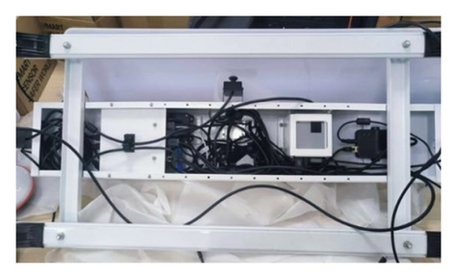
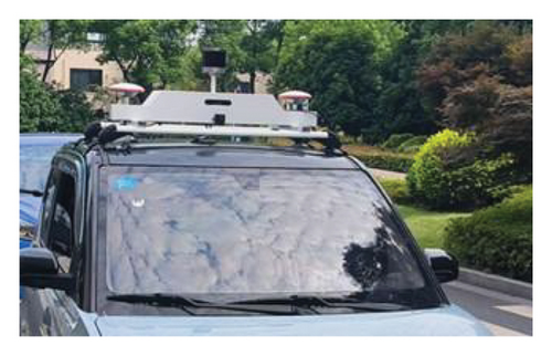
In the field experiment, we get the 3D point cloud data of vehicles at underground parking environment; the working flow of multisensor data interaction system is as shown in Figure 16.
4.2.2. Data Processing
We stored the point cloud data from north and south areas in two bags, respectively, and calibrate the camera internal parameters and camera radar external parameter information as shown in Figure 17.

In order to verify the accuracy of multisensor data, camera internal parameters, and camera radar external parameters, the R3live is used for multimodal data fusion to generate RGB point cloud scene model. The point cloud scenes’ model maps of the two areas are shown in Figure 18.
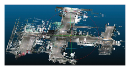
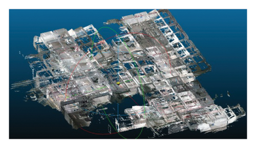
4.2.3. Data Analysis
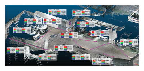
In the colored point cloud model established through R3live, we randomly marked 398 feature points containing special objects such as ground signs, support columns, signs, and fire cabinets and then combined them in pairs to obtain 199 feature point distances as shown in Figure 19.
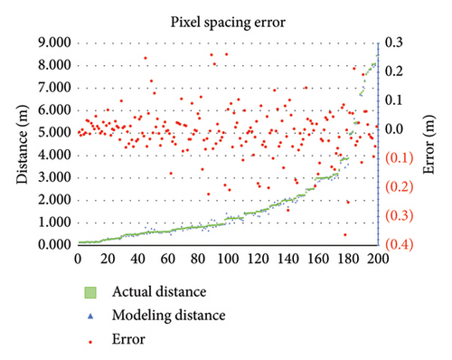
We express the actual measured distance by Si, the model calculated distance by , and the distance error by () and calculate the distance error of the 199 feature points as shown in Figure 20. It can be seen that the point distance is between 0 and 8.4 m and the point distance error is between −0.37 and +0.27 m as shown in Figure 20.
| Index | Value (m) |
|---|---|
| ME | −0.00901 |
| MAE | 0.059 |
| MSE | 0.00766 |
| SD | 0.087 |
5. Discussion and Conclusions
In this paper, we developed a LBCINS for underground parking. First, we introduced the Lidar technology in the context of ISN and proposed the integrated navigation system that combined the INS and Lidar-binocular camera. Then, to preliminary match the results and performance of the LBCINS under the Lidar-NDT algorithm, simulation experiment in Gazebo is designed. The simulation results show that in the complex environment of underground parking, the INS under the NDT algorithm and the binocular camera achieves better performance. Finally, field experiment results show the INS and Lidar-binocular camera-combined navigation system proposed in this research have a high precision of distance position compared with actual distance. The significance of this research is to establish an INS based on a Lidar-binocular camera so that the system can be applied to an underground parking navigation environment and provide a good research basis for exploring Lidar and binocular cameras on INS.
In the research of INS nondestructive detection under the NDT algorithm, there is a lack of data processing and optimization process for the pixel data of target obstacles, which leads to a long pixel data processing time for obstacle targets. Also, there is no specific experimental analysis of the specific underground parking environment. Thus, a performance analysis of the LBCINS carried out based on the recognition of different obstacles encountered in underground parking is needed. In the future research, the performance analysis of the LBCINS should be combined with the specific underground parking environments, making the integrated navigation system combined with real maps to apply the proposed system to the navigation system in more practical scenarios.
Conflicts of Interest
The authors declare no conflicts of interest.
Funding
This work was jointly supported by the Fundamental Research Funds for the Central Universities under Grant B240201136, the Jiangsu Funding Program for Excellent Postdoctoral Talent under Grant 2024ZB335, and the Qingpu District Industry University Research Cooperation Development Foundation under Grant 202314.
Open Research
Data Availability Statement
The data that support the findings of this study are available from the corresponding author upon reasonable request.


