NanoDet Model-Based Tracking and Inspection of Net Cage Using ROV
Abstract
Open sea cage culture has become a major trend in mariculture, with strong wind resistance, wave resistance, anti-current ability, high degree of intensification, breeding density, and high yield. However, damage to the cage triggers severe economic losses; hence, to adopt effective and timely measures in minimizing economic losses, it is crucial for farmers to identify and understand the damage to the cage without delay. Presently, the damage detection of nets is mainly achieved by the underwater operation of divers, which is highly risky, inefficient, expensive, and exhibits poor real-time performance. Here, a remote-operated vehicle (ROV)-based autonomous net detection method is proposed. The system comprises two parts: the first part is sonar image target detection based on NanoDet. The sonar constantly collects data in the front and middle parts of the ROV, and the trained NanoDet model is embedded into the ROV control end, with the actual output of the angle and distance information between the ROV and net. The second part is the control part of the robot. The ROV tracks the net coat based on the angle and distance information of the target detection. In addition, when there are obstacles in front of the ROV, or it is far away from the net, the D-STAR algorithm is adopted to realize local path planning. Experimental results indicate that the NanoDet target detection exhibits an average accuracy of 77.2% and a speed of approximately 10 fps, which satisfies the requirements of ROV tracking accuracy and speed. The average tracking error of ROV inspection is less than 0.5 m. The system addresses the problem of high risk and low efficiency of the manual detection of net damage in large-scale marine cage culture and can further analyze and predict the images and videos returned from the net. https://youtu.be/NKcgPcej5sI.
1. Introduction
The world’s ocean covers an area of approximately 360 million square kilometers, with huge potential for the development and utilization of marine living resources [1, 2]. Aquatic products play an increasingly important role in human nutrition, and fish remains a prevalent commodity in the global market [3–6]. Recently, with the increasing demand for animal protein and the severe decline in conventional fishery resources, the world’s fisheries, with Marine fishing as the main body, are gradually transforming to aquaculture. Mariculture has become the primary approach to achieving a sustainable supply of aquatic products [7, 8].
Owing to the high water exchange rate and low pollutant content in the open sea area, cage farming [9] and open sea platform farming have become a new mode of fishery production, thereby providing hygienic, healthy, and high-quality seafood [10–14]. In the past two decades, the production of seawater cage culture has gradually expanded worldwide. However, the marine environment is complex and unpredictable, and several factors, such as a fish epidemic, invasion of exotic species, and destruction of net cages, are uncontrollable [15]. Broken nets can cause large numbers of fish to escape and inflict severe damage if not detected in time. According to the statistics of fish escape accidents in Norway, more than 60% of escapes were caused by the failure of farming equipment [14, 16 ], which mainly included cage wear, tears, and fish bites. Therefore, it is necessary to identify the damaged position of the net in time and repair it accordingly [17–19].
Presently, net cages are primarily inspected manually. However, this approach is conducted in a complex underwater environment with low visibility and a large net area; hence, it is time-consuming, dangerous, and inefficient. However, remote-operated vehicles (ROVs) operated underwater instead of divers exhibit flexible properties and are operated with cameras to inspect the netting suits. In addition, an ROV equipped with a camera and laser [20] can calculate the relative distance and speed of the cage. To obtain position information more accurately, the ROV system integrated the Doppler velocity log (DVL) and ultrashort baseline [21]. The relative distance, angle, and speed information of ROV relative to the net can be accurately obtained. A method to guide ROVs autonomously using aquaculture netting bars has been presented [22]. By adopting a forward-looking DVL, the netting can be approximated as a plane from four DVL beam vectors. Then, the approximate direction and position of the ROV relative to the net coat are employed as the input of the line-of-sight (LOS) guidance rule to guide the ROV to the required path and complete autonomous inspection. The feasibility of the proposed method is verified via simulation and offshore experiments. Wu et al. [23] obtained the azimuth angle between the ROV and net suit via sonar, designed an ROV net suit inspection scheme based on PID and NN hybrid drive control, realized fully autonomous net suit tracking and actual net suit inspection, and achieved verified efficiency in the complex environment of the open sea. In summary, the detection of the net in deep and open sea cages has been widely researched by experts and scholars, and a series of schemes to replace artificial underwater operations have been proposed. However, owing to the high cost of sensors or the laboratory experiment stage, they cannot be applied in actual production.
Optical cameras cannot obtain clear underwater image information owing to poor vision due to poor underwater environment and turbidity. However, sonar can provide high-quality image data under turbidity and low light conditions [24]. Based on sonar data, the angle and distance data of obstacles or tracking targets can be calculated to avoid the collision between underwater robots and obstacles and achieve safe and efficient underwater target tracking [25]. In addition, compared with optical images, sonar images have smaller files, which can reduce the pressure of data transmission and processor calculation, improve the processing speed of sonar images, and provide optimal real-time performance [26, 27]. Therefore, a tracking method based on sonar image recognition is proposed in this study. The D-STAR algorithm is adopted to realize the local path planning. Finally, the actual detection of the net is realized using the onboard camera. The sonar image is utilized to locate the position of the net suit instead of the sonar scan line, which can circumvent the interference of aquatic organisms with the system, accurately calculate the distance and angle relationship between the ROV and net suit, effectively reduce the tracking error, and realize the precise inspection of the robot.
2. Materials and Methods
2.1. Robotic Platform
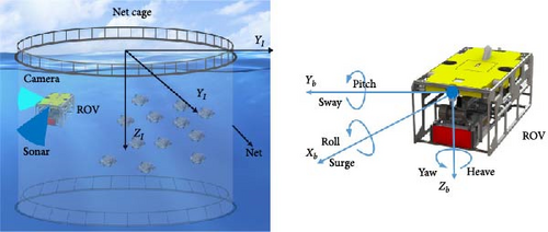
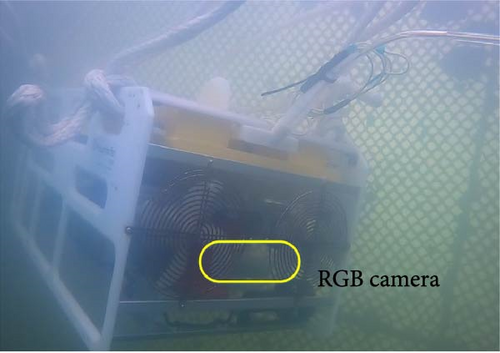
Here, we present the modeling of the ROV and its sensor suite employed in this study. The underwater vehicle has a nonlinear 4-DOF model. The sensors used include sonar, inertia measurement unit, and RGB camera. The robot framework is illustrated in Figure 1.
2.2. Experimental Environment
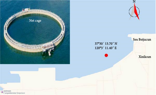
The experiment was conducted in Bohai Bay, approximately 5 km away from the shore. The cage diameter, water depth, and wave height were approximately 128 m, 11 m, and 0.2–0.6 m, respectively, as illustrated in Figure 2.
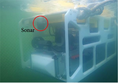
Because underwater is a low-light, multidisturbance environment, the underwater vehicle will be affected by waves and currents; hence, making it difficult to control. The proper angle and distance should be maintained at all times during the inspection of the underwater net. The distance between the ROV and the net is 1 m, and the RGB camera and net are taken at a vertical angle. Set the running speed of the robot to 0.3 m/s and start shooting the net with the RGB camera at a rate of 30 fps, as shown in Figures 3 and 4.


2.3. Detection and Characterization Based on a NanoDet
The proposed method is based on sonar images. In the moving process, the underwater robot continuously scans the underwater environment to generate images. First, the generated original sonar images were enhanced. The contrast-constrained adaptive histogram equalization (CLAHE) algorithm [28, 29] was utilized. To address the problem that the local histogram equalization algorithm may lead to blocking effect and overamplified noise [30, 31], the two important steps of the CLAHE algorithm include trimming the histogram and determining the mapping relationship of each pixel via linear interpolation. The principle of histogram clipping is as follows:
If the height of the histogram is higher than Hmax, the part cutoff cannot be ignored directly. The values of the cutout parts should be evenly distributed throughout the gray range to ensure that the total area of the histogram remains the same. Another important part of CLAHE is an interpolation, which can significantly reduce the block effect. As aforementioned, the CLAHE algorithm divides the image into several subblocks of the same size, which can be divided into three groups, which include the corner, boundary, and inner regions. Pixel interpolation processing is conducted for the angle region, mapping function, and subblock pixel center pixel. For a pixel in the boundary region, its mapping function is obtained via the linear interpolation of the mapping function of the center pixel of two adjacent subblocks of the pixel.
Subsequently, the enhanced sonar image is input into the trained NanoDet model. As the output of the algorithm, the net coat is detected, the bounding box with center coordinates is detected, and the distance and angle relationship between the AUV and net cost is calculated.
This function can eliminate the center-ness branch of FCOS, significantly circumvent convolution on this branch, and ultimately reduce the computation overhead of the detection head. It can provide the same performance as the YOLO series, is lightweight for the three major modules of the single-stage detection model (Head, Neck, Backbone), exhibits fast target detection, and is easy to train and transplant. The overall architecture of the system based on the NanoDet model is illustrated in Figure 5.

To achieve lightweight, NanoDet employs ShuffleNetV2 1.0x as the backbone network, eliminates the last layer of the network’s convolution, and extracts 8, 16, and 32 times downsampled features into PAN for multiscale feature fusion. In the feature pyramid network (FPN) module, all convolution is discarded, and only 1X1 convolution extracted from backbone network features is retained for the alignment of feature channel dimensions. Up- and downsampling are completed via interpolation. The multiscale feature map is directly added, which reduces the computation amount of the entire feature fusion module significantly.
In the detection header module, the detection header with shared weight is employed; that is, the same set of convolution prediction detection boxes is used for the multiscale feature map out of FPN, and then a learnable scale value is adopted for each layer as the coefficient to scale the predicted boxes. To achieve lightweight, we first replaced the ordinary convolution with the depth-separable convolution and reduced the number of convolution stacks from 4 to 2. Regarding the number of channels, you can obtain the parallel speedup of most inference frameworks by compressing 256 dimensions to 96, keeping it at a multiple of 8 or 16.
2.4. Path Planning Based on the D-STAR Algorithm
During underwater inspection, once the net is encountered, it may be damaged, and the fish may escape. Therefore, the ROV should maintain a certain distance when tracking the net. Here, the D-STAR algorithm [34–36] realizes the local path planning. D-STAR is easy to calculate and can adapt to the underwater dynamic and complex environment to ensure that space collision is minimized in the inspection process of underwater vehicles, thereby reducing the safety risk caused by space collision [37, 38]. In the NanoDet detection framework, the output position of the center of the detection target is considered the target position (xi, yi) of D-STAR, and the position of the underwater vehicle (xRov, yRov) is considered the initial position of D-STAR. The actual path planning framework of the underwater vehicle dynamic path planning based on D-STAR is illustrated in Figure 6.

A map of 0,1 can be generated according to the above formula, where 0 and 1 denote no obstacle and an obstacle, respectively. In this system, threshold = 80 is set for the sonar image threshold, as illustrated in Figure 6b.
3. Results
3.1. Model Performance Comparison
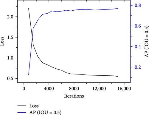
The model was implemented based on the deep learning framework, PyTorch. In the training process, the initial value of the learning rate was 0.0001, and the cosine annealing strategy was adopted to reduce the learning rate. The number of epochs and batch size were set to 15,000 and 64, respectively. The NanoDet model was trained over 15,000 iterations. Figure 7 presents Loss and AP (IOU = 0.5) as a function of the number of iteration steps. In the first 2000 steps, the loss decreased rapidly, then gradually slowed down, and finally stabilized at ~0.55. In addition, the AP value fluctuated between 0.74 and 0.78.
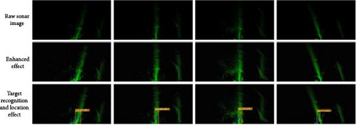
As illustrated in Figure 8, the first row presents the original sonar image, the second row illustrates the enhanced sonar image and the third row presents the detection result of NanoDet. From Figure 8, we infer that the detection accuracy was improved after image enhancement, and the tracking error of the underwater vehicle was reduced.
In addition, for real-time detection and testing of 200 random sonar images, compared with the conventional algorithm for the YOLOv5 model, the speed has a significant advantage under the condition of negligible difference in accuracy. Specific parameter comparisons are presented in Table 1.
| Network | My data AP (IOU = 0.5) |
Resolution | Run time 1FPS | Params | Weight size |
|---|---|---|---|---|---|
| YOLOv5s | 78.5 | 400 X 200 | 110.7 ms | 7.2 M | 14.4 M |
| NanoDet | 77.2 | 400 X 200 | 43.2 ms | 0.95 M | 7.37 M |
| Network | 200 images recognition test (accuracy) | 200 enhanced images recognition test (accuracy) | |||
| YOLOv5s | 98% | 98.5% | |||
| NanoDet | 98% | 99.5% | |||
| Network | 60-s continuous frame video detection (1800 frames in total) | ||||
| YOLOv5s | 17 frames (not detected) | ||||
| NanoDet | 2 frames (not detected) | ||||
In summary, this study proposed a NanoDet-based sonar image target recognition that can realize target detection in an underwater complex environment, output real-time range, and angle data, and satisfy the requirements of ROV path tracking.
3.2. Net Tracking Experiment
In the field test in Bohai Bay, the weather was clear, the wave height was less than 0.3 m, and the underwater velocity was less than 0.2 m/s. When the ROV encounters a fish, it will avoid damaging the fish by avoiding obstacles while planning a path around the obstacle and returning to the global path, as illustrated in Figure 9.

In Figure 9, an ROV avoiding obstacles in water is shown. Experimental video: https://youtu.be/xWv3cOLtlPQ.
The attitude, tracking error, distance error, and angle error of the ROV and net were analyzed. The test was conducted on the inspection of the net at different depths of 2 m, 4 m, and 6 m, respectively, and the experimental results were analyzed.
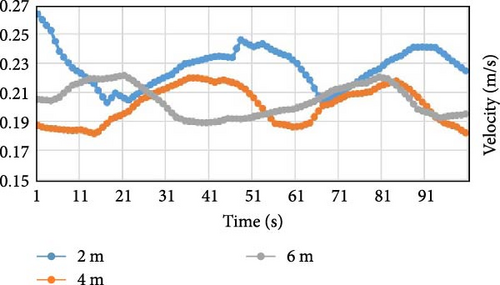
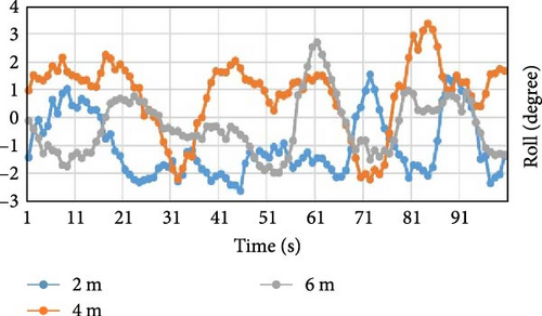
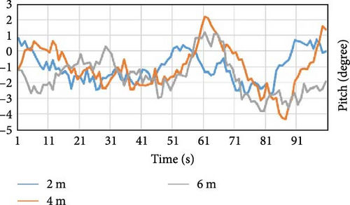
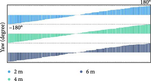
Figure 10a presents the operating speed of the AUV. The variation of speed varies with the depth of the robot. The deeper the depth, the less the disturbance from the wind and waves on the sea surface, and the smaller the variation in the speed. Figure 10b,c presents the roll and pitch angles of the robot, respectively. The deeper the robot, the less the effect of the wind and waves on the sea surface. Figure 10d presents the change in the heading angle of the underwater vehicle during a round inspection. The deeper it is, the less it is affected by waves and currents.
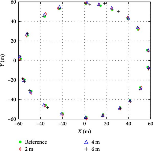
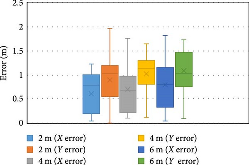
As illustrated in Figure 11, the tracking position errors of the ROV at different depths during the inspection are 1.65, 1.36, and 1.24 m on average for 2, 4, and 6 m, and 2.73, 2.03, and 1.82 m at maximum. As illustrated in Figure 12, the average errors of the X and Y axis during the 2-m inspection are 0.6 m and 0.9 m, respectively, and the maximum errors are 1.23 and 1.97 m. During the 4-m inspection, the average errors of the X and Y axes were 0.69 m and 1.02 m, respectively, and the maximum errors were 1.11 and 1.59 m. The average errors of the X- and Y-axes during the 6-m inspection were 0.79 m and 1.28 m, respectively, and the maximum errors were 1.82 and 1.73 m.
As illustrated in Figure 13, the distance between the AUV and net is too large. Owing to the low underwater visibility, the image of the net was blurred, which severely affects the accuracy of the damaged parts of the net. If the distance between the underwater robot and the net is negligible, the field of vision becomes smaller, and a blind area emerges with the possibility of missing detection. In the implementation, the ideal tracking distance was set to be between 0.5 and 1.5 m. The experimental results indicate that the tracking distance of the three experiment groups is basically within the ideal range. In the experiment, which was only 2-m deep, the tracking distance reached 1.6 m owing to the influence of the waves, and the underwater vehicle quickly adjusted and returned to the ideal tracking range.
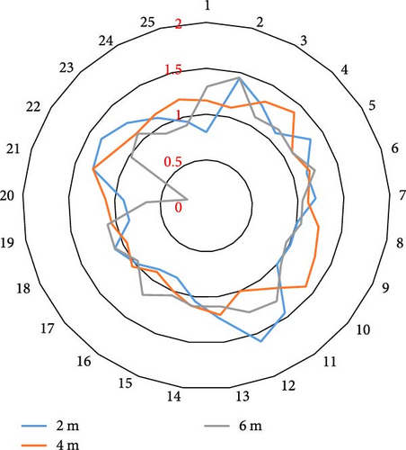
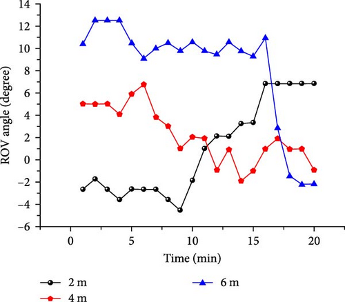
Figure 14 presents the angle relationship between the camera and net during the underwater inspection of the underwater robot. Ideally, the best effect can be achieved when the camera is perpendicular to the net (Figure 4a). The larger the angle between the camera and the net, the more difficult it is to ascertain the damage to the net. Particularly, in the underwater complex environment, when the angle error between the underwater camera and net is within ±20°, the shooting and detection of the net can be completed. The experimental results indicate that the angle error between the underwater camera and the net in the three experiment groups is less than 20°.
According to the experimental data, it can be inferred that the robot can inspect the net independently. The sea environment is complex, and different depths exert different effects on the robot. According to the three groups of experimental results, the experimental results of the 2 m depth are significantly affected by waves, especially the speed and attitude of the underwater robot. At 4 and 6 m, they are less affected by waves, and the attitude of the underwater robot is relatively stable.
4. Conclusions
Here, a deep learning model based on NanoDet was designed to detect the damage of the net in the open sea cage culture. It can detect the target in actual sonar images, return the distance and angle data between the ROV and the net, and realize the tracking of the net using the ROV. RGB shoots the net and sends the shots back to the control terminal in real-time, thereby replacing the inspection of manual underwater operations. ROV underwater autonomous net inspection exhibits high flexibility, fast swimming speed, and certain anti-interference abilities. It can shoot the net comprehensively and without dead angles. It addresses the problems of poor flexibility, poor visual field, and low efficiency in manual underwater operation. The ROV system adopted for underwater net inspections is innovative and efficient. The obtained results indicate that the proposed method can effectively detect the underwater net.
According to the experimental results, the authors put forward the following prospects: (1) further optimize the sonar image detection method, filter out the outliers in the data when the sonar obtains the original data, and improve the detection accuracy; (2) further improve the intellectualization of inspection, introduce the damage detection of the net in the RGB camera return part, automatically send out an alarm if damage is detected, and completely liberate labor requirements.
Ethics Statement
This article does not contain any studies with human participants or animals performed by any of the authors.
Consent
Informed consent was obtained from all individual participants included in the study.
Disclosure
This study belongs to the field of fishery intelligent equipment and does not involve patients and related issues. No other protected material is reproduced in this paper.
Conflicts of Interest
The authors declare no conflicts of interest.
Funding
This paper has been funded by Key Projects, but it is inconvenient to publish because the project involves secrets.
Open Research
Data Availability Statement
The data will be made available upon request.


