Structural, Mechanical, Electronic, and Optical Properties of CsCdX3 (X = Cl, Br, and I): A Comparative Study Using First Principle Calculation
Abstract
This study presents a comparison of structural, optical, mechanical, and electronic characteristics of CsCdX3 (X = Cl, Br, and I) by employing first principle calculations. We performed this calculation using the general gradient approximation (GGA) scheme within the Perdew–Berke–Ernzerhof (PBE) functional, which is carried out by the Cambridge Serial Total Energy Package (CASTEP) system. The computation’s validity is validated by a comparison of accessible mathematical and experimental findings. The computed lattice constants show excellent consistency with those obtained from the theoretical calculation and experimental techniques. The computed result explicates that when the larger halogen is substituted for the smaller one, the cell volume and lattice parameter of CsCdX3 (X = Cl, Br, and I) increase. The obtained mechanical characteristics evidence that CsCdX3 (X = Cl, Br, and I) compounds are ductile, and ductility increases with the replacement of Cl with Br and I, respectively, and CsCdI3 exhibits the highest amount of ductility. Indirect bandgap semiconductor to metallic transition is found in the energy band diagrams when I occupies the X site of CsCdX3 instead of Cl and Br. Furthermore, the absorption coefficient, the dielectric constant, conductivity, and refractive index demonstrate that when Cl is replaced by I and Br, redshift occurs in the optical spectra. Among the compounds, the reflectivity of CsCdI3 is the highest in the IR region, making CsCdI3 suitable as an IR reflector. But in the UV region, CsCdCl3 could be suitable as a UV reflector.
1. Introduction
Researchers are looking for advanced materials with a wide range of applications to meet technological challenges in the future. Because of this, a variety of the material’s features have been thoroughly researched in recent years to use them effectively in cutting edge technology. Experimental and theoretical investigations may be used to examine the physical characteristics of materials [1]. Perovskites have gained significant attention from scientists and researchers in recent times due to their remarkable chemical and physical properties, including superconductivity, semiconductivity, ferroelectricity, thermoelectricity, piezoelectricity, catalytic activity, colossal magnetoresistance, half-metallic transport, and ferromagnetism [2–10]. Furthermore, their diverse range of applications, such as optoelectronic devices, photovoltaic cells, photodetectors, LEDs, etc. [11–18], has made them attractive to the scientific community. Perovskites are also considered to be significant materials in the photocatalytic sector because of their excellent stability and broad absorption spectrum, which generate electron–hole pairs that facilitate photoelectrochemical reactions [19]. Numerous experimental and theoretical techniques have been developed to investigate different properties of perovskites [20, 21]. One theoretical approach that is gaining traction and showing a lot of promise is the density functional theory (DFT) [22–26], as it gives more accurate and consistent results close to the experiments [27–31].
Owing to the unique optoelectronic characteristics, halide perovskites are gaining interest from photovoltaic researchers [32–34]. Halide perovskites are thought to originate from a parent phase with the generic formula ABX3 (wherein X symbolizes halides, A symbolizes a cation, and B symbolizes a heavy metal cation, such as Pb, Cd, etc.). Till today, halide-based cells have the greatest possible power conversion efficiency (PCE) among all perovskites, coming in at 25.5% [32, 35–37]. Cesium (Cs)-based halide perovskites have received great attention in the photovoltaic industries because of their high absorption coefficient in the visible and ultraviolet spectrum [38]. It was demonstrated that CsSnX3 and CsPbX3 possess appropriate band gaps and impressive absorption coefficients [32–34], rendering them potential prospects for employment in the solar sector. Like other Cs-based halide perovskites, Cs-cadmium (Cd)-based perovskites are also promising materials for various sectors because of their remarkable properties. CsCdCl3 has excellent thermal and electric properties, making it a viable thermoelectric material for automobile industries [39]. Also, CsCdCl3 is a promising candidate for various optical devices, owing to their strong absorption coefficient [38]. CsCdX3 (Cl and Br) is also found to be a potential candidate for sprintonic applications when doped with C and N because of their strong magnetic properties [40].
Like other Cs-based perovskites, multiple studies were conducted on CsCdX3 (X = Cl and Br) [41, 42]. The mechanical, optical, electrical, and structural characteristics of CsCdCl3 were investigated in earlier studies in both pressured and nonpressurized circumstances, and the obtained results elicited the fact that CsCdCl3 possesses indirect band gaps [41, 42]. Further, the electronic, magnetic, and structural characteristics of CsCdBr3 were reported with B, C, and N dopants [32, 40]. It was found that CsCdBr3 is an indirect semiconductor and a nonmagnetic material. However, when B, C, and N were doped into the Br sites of CsCdBr3, ferromagnetic characteristics were discovered. Apart from this, these materials have exceptional optical characteristics in the UV, making them very promising for use in optoelectronic devices in the UV range [42]. As far as we are aware, no theoretical or experimental investigations have been conducted on CsCdI3. Furthermore, no research has yet been done on the optical and mechanical characteristics of CsCdBr3. Therefore, employing first principles calculations, it is possible to investigate the mechanical, optical, electronic, and structural characteristics of CsCdX3 (X = Cl, Br, and I) and compare the outcomes.
In this study, we used density functional theory to analyze the structural features, mechanical characteristics (Young’s modulus, bulk modulus, share modulus, Pugh’s ratio, Poisson’s ratio, Cauchy pressure, machinability index, Vickers hardness, and anisotropy), electronic characteristics, and different optical characteristics of CsCdX3 while X is replaced by Cl, Br, and I, respectively, and compared these calculated results among these three materials. We also have calculated the chemical and mechanical stability, ductility, and brittle nature of these three compounds.
2. Computational Method
In this study, first principles calculations within the DFT framework have been conducted [43, 44] employing the Cambridge Serial Total Energy Package (CASTEP) [45]. To investigate the characteristics, CASTEP primarily utilizes the plane wave pseudopotential total energy approach [46]. Utilizing the Perdew–Berke–Ernzerhof (PBE) functional and the general gradient approximation (GGA), the electronic exchange-correlation energy is computed [47, 48]. Ultrasoft pseudopotentials of Vanderbilt type are used to simulate the interaction between valence electrons and ion cores [46]. The ideal crystal structure was precisely guaranteed by utilizing the Broyden–Fletcher–Goldfarb–Shanno (BFGS) technique [49], which offers a quick method to identify the building with the lowest energy. A plane wave energy cutoff of 660 eV along with a k-point mesh of 8 × 8 × 8 was employed to ensure accurate structural and characteristic estimations. The convergence tests with respect to key parameters, such as the plane wave cutoff energy and k-point sampling, to ensure that the method converges efficiently and provides reliable results, the convergence graph is displayed in Figure S1 in the supporting manuscript. To sample the Brillouin zone of the k-points, the Monkhorst–Pack method was employed [50]. The stress–strain method was applied in typical circumstances to obtain the studied model’s elastic stiffness constants [51]. The strain magnitude was adjusted to 0.003 to get the best results. The following criteria were set for convergence: total energy = 5 × 10⁻⁶eV/atom, maximum stress = 0.02 GPa, maximum force at 0.01 Å, and maximum displacement = 5.0 × 10⁻⁴Å.
3. Results and Discussions
3.1. Structural Properties
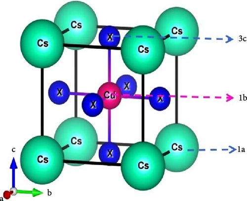
The CsCdX3 compound, where X symbolizes Cl, Br, or I, has a cubic crystal structure having the space group Pmm (#221). The crystalline structure of CsCdX3 was illustrated employing the VESTA software [52], as shown in Figure 1. The crystal lattice of CsCdX3 comprises five atoms, with X representing the halogens Cl, Br, or I. The Cs atom is positioned at coordinates (0, 0, 0) and occupies Wyckoff position 1a, while the Cd atom is situated at coordinates (0.5, 0.5, 0.5) and occupies Wyckoff position 1 b. The X (X = Cl, Br, and I) atoms occupy Wyckoff position 3 c at coordinates (0.5, 0.5, 0). Together with the prior simulated and experimental data, Table 1 displays the estimated lattice constants and cell volumes of CsCdX3. The calculated lattice constant of CsCdCl3 deviates, respectively, by 2.36% and 0.08% from the experimental and computational work and by 0.1% for CsCdBr3 from the theoretical work, which indicates the accuracy of the calculation of this work. A comparison table of our calculated lattice parameters and band gaps, alongside previously studied and experimental data, is provided in Table S5. As far as Table 1, when a smaller atomic size halide is replaced by a larger one, the lattice parameter of CsCdX3 increases. When Br and I replace Cl, the lattice parameters become 5.619 Å and 6.045 Å, respectively. Table 1 also shows the cell volume of CsCdX3, which is found to increase gradually when Cl is replaced by Br and then by I.
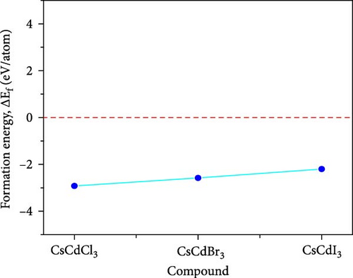
Here, Es(X), Es(Cs), and Es(Cd) correspond to the energies of X (Cl, Br, and I), Cs, and Cd respectively, while Etotal(CsCdX3) specifies the system’s (unit cell) total energy. The negative value of ΔEf(CsCdX3) demonstrates that CsCdX3 is chemically stable [54]. Figure 2 also visually displays the examined compounds’ negative formation energy. For structural stability, the tolerance factor (t) is calculated using the following formula:
The usual tolerance factor ranges from 0.8 to 1 for cubic perovskite. Table 1 demonstrates that the tolerance factor of CsCdCl3, CsCdBr3, and CsCdI3 are 0.95, 0.93, and 0.92, respectively. So, all three compounds are structurally stable.
3.2. Mechanical Properties
Elastic and mechanical characteristics are critical for materials intended for applications in devices. These properties also help understand how a material will respond under stressed conditions. Calculating elastic constants is necessary to assess a material’s stability, stiffness, ductile-brittle nature, hardness, machinability, isotropic-anisotropic properties, and bonding nature [55, 56]. The calculated elastic constants (Cij) for CsCdX3 are presented in Tables S1–S4 in the supporting information. The Born stability criteria [43] are, C11 > 0, C11 − C12 > 0, C11 + 2C12 > 0 and C44 > 0, which is used to assess the mechanical stability of a material that is subject to the condition that the elastic constants must be greater than zero for the cubic structure. These elastic constants were obtained using the “stress–strain” premise and plotted in Figure 3. It can be observed from the plot that C11, C44, and C12 are greater than zero, confirming the mechanical stability of all three compounds.
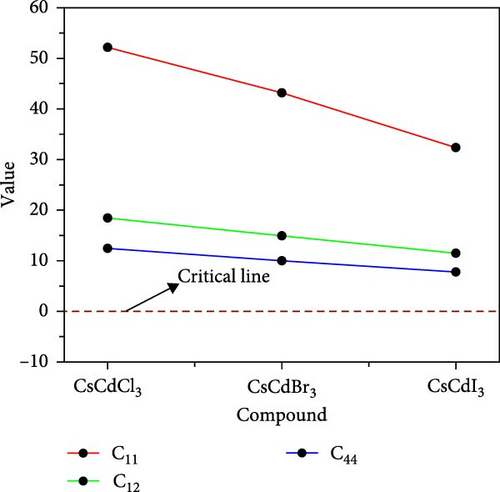
Table 2 provides an estimation and listing of various mechanical features of CsCdX3, such as Young’s modulus (E), bulk modulus (B), shear modulus (G), Poisson’s ratio(υ), Pugh’s ratio (B/G), Machinability index (μM), Vicker’s hardness (Hv), universal anisotropic factor (AU), and Zener anisotropic factor (A). These features are obtained using elastic constants. The Vigot–Reuss–Hill (VRH) method is applied to comprehend how solids behave mechanically under different circumstances [57]. For cubic lattices, the Voigt bulk modulus (BV) and Voigt shear modulus (GV) are defined as follows [58]:
| Properties | CsCdCl3 | CsCdBr3 | CsCdI3 |
|---|---|---|---|
| Bulk Modulus, B | 29.6676 | 24.3384 | 18.8305 |
| Shear Modulus, G | 14.0519 | 11.5013 | 8.7414 |
| Young Modulus, E | 36.4078 | 29.8084 | 22.7101 |
| Pugh’s ratio, B/G | 2.11 | 2.12 | 2.15 |
| Poisson’s ratio, υ | 0.295 | 0.296 | 0.300 |
| Vickers Hardness, Hv | 1.916 | 1.565 | 1.171 |
| Cauchy pressure, C12 − C44 | 5.9881 | 4.8965 | 4.1078 |
| Machinability Index, μM | 2.39 | 2.43 | 2.43 |
The B is the fracture resistance, and materials with higher B values tend to be more resistant to fracture compared to those with lower B values. Table 2 revealed that CsCdCl3 exhibits the highest B value and decreases when Br and I are used as substitutes for Cl, respectively. Thus, among the three compounds, CsCdCl3 shows the highest fracture toughness. The G indicates the plastic deformation resistance and increases with the value of G. Table 2 demonstrates that CsCdCl3 has the highest value of G and decreases whenever Br and I are substituted for Cl, respectively. Young’s modulus (E) assess a material’s stability or resilience against flexible distortion under load. From Table 2, it is observed that CsCdCl3 shows greater stiffness than the other two materials.
The μM is estimated to be 2.39 for CsCdCl3 but for CsCdBr3, and CsCdI3 the μM is found to be the same and 1.02 times greater than the value of CsCdCl3.
If AU has a zero value, the substance is isotropic. The discrepancy from this value defines the corresponding level of anisotropy. All three compounds exhibit very little anisotropy, as Table 3 shows.
| Compound | A1 | A2 | A3 | A | AG | AB | AU | Aeq |
|---|---|---|---|---|---|---|---|---|
| CsCdCl3 | 0.737554 | 0.737554 | 0.737554 | 0.737554 | 0.011082 | 0 | 0.112064 | 1.355833 |
| CsCdBr3 | 0.707993 | 0.707993 | 0.707993 | 0.707993 | 0.014246 | 0 | 0.144523 | 1.412443 |
| CsCdI3 | 0.743068 | 0.743068 | 0.743068 | 0.743068 | 0.010548 | 0 | 0.106608 | 1.345773 |
([001] plane)
Spherical 3D images reflect the isotropy, while nonspherical images reveal the anisotropy [63]. The amount of anisotropy is quantified by measuring its divergence from the spherical form, and the anisotropy increases with the deviation. Figure 4 reflects that, in comparison to other compounds, CsCdBr3 exhibits a slightly greater amount of anisotropy.


3.3. Electronic Properties
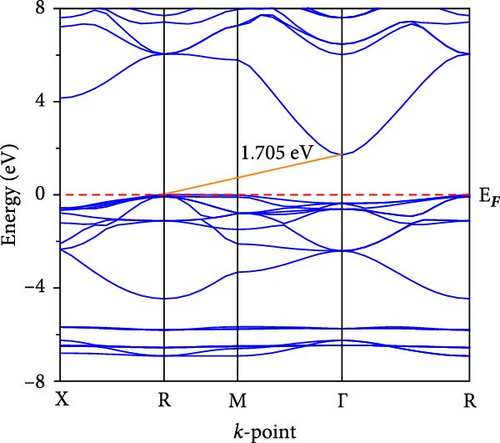
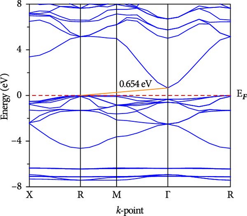
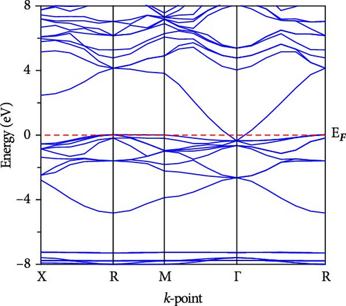
The electronic band dispersion profile is essential for understanding electron transport mechanisms in a solid. We calculated the band dispersion profile of CsCdX3 (X = Cl, Br, and I) in the Brillouin zone’s high symmetry paths (X, R, M, Γ, and R) and plotted it in Figure 5. The red horizontal dotted line at 0 eV (EF) symbolizes the Fermi level. The band dispersion profile of CsCdCl3 demonstrates that it is an indirect (R- Γ) bandgap semiconductor having a bandgap of 1.705 eV. But when Br replaces Cl, the conduction band (CB) approaches the fermi level, the indirect gap at R- Γ reduces and is found to be 0.654 eV. Further, the band gap reduces to 0 eV at Γ point when I. Thus, replacing Cl, CsCdI3 exhibits metallic behavior. For these substances, there isn’t yet an experimental band gap, so the validity of our results is confirmed by comparing them against previously published (theoretical) findings, as shown in Table 4. It is found that our calculated band has excellent consistency with the previously computed band gap. It is also found that there is an inverse relation between the bandgap and nuclear size of the halogen in halide perovskite. The band gap reduction may be connected with electronegativity, which decreases with the atomic size of the halogen atom.
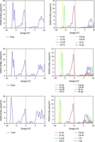
The band structures can also be explained by the total density of states (TDOS) shown in Figure 6, whereas the red horizontal dotted line at 0 eV symbolizes the Fermi level. As seen in the figure, the semiconducting behavior of CsCdCl3 and CsCdBr3 is indicated by their zero TDOS values being close to the Fermi level. However, TDOS exhibits a little rise close to the fermi level when I replace Cl, suggesting that the substance is metallic. Thus, TDOS justifies the statement of the band structure. The PDOS further explains this behavior. When “I” take the place of “Cl”, Cd-5s states shifted toward the Fermi level, and I-5p displays a little peak close to 0 eV. Hence, the minor peak in the TDOS near 0 eV is caused by the combination of I-5p and Cd-5s states. This indicates the metallic nature of CsCdI3. Again, TDOS shows that when I substitute Cl, the CB peak progresses further toward the lower energy region. The presence of halogen p states is the primary cause of the valance band (VB) peak around the fermi level, as depicted in Figure 5. On the contrary, in the conduction band, Cs-4d and Cs-5p contribute the most to the CB, while there is a small contribution from Cs-6s, Cd-4p, and s states of halogens. The band gap reduction mainly occurs due to the contribution of halogens.
3.4. Optical Properties
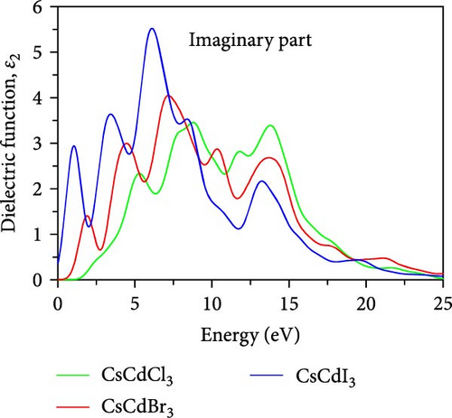
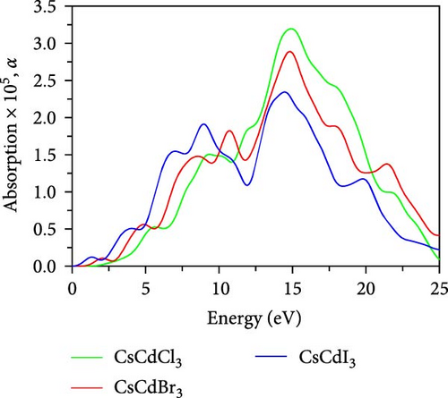
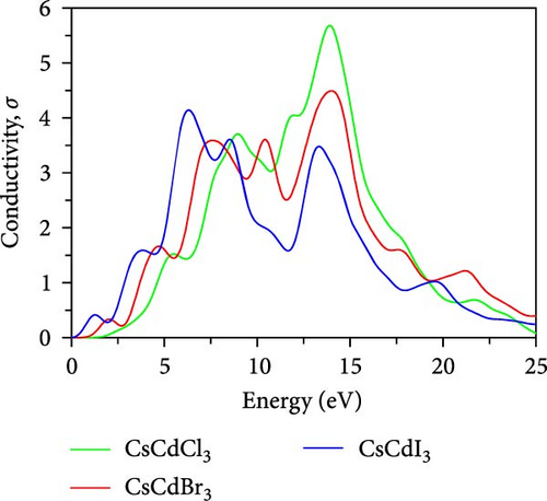
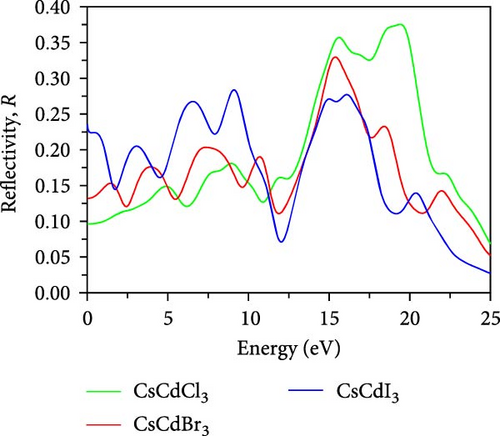
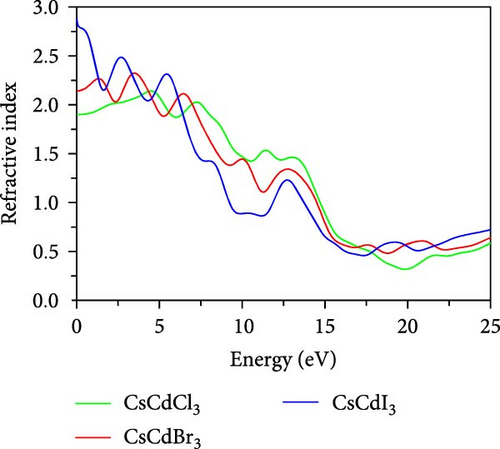
Optical characteristics, which vary depending on the kind of substance and the incoming radiation, may be used to understand how light interacts with substances. The important optical characteristics, including conductivity, reflectivity, absorption, dielectric function, and refractive index, are measured for CsCdX3 and plotted in Figure 7. The dielectric function can be expressed by ε(ω) = ε1(ω) + ε2(ω) ,where ε1(ω) and ε2(ω) symbolizes the real and imaginary parts of the dielectric constant, respectively. The real part of the dielectric constant is mathematically derived by the Kramers–Kronig transformation [66].
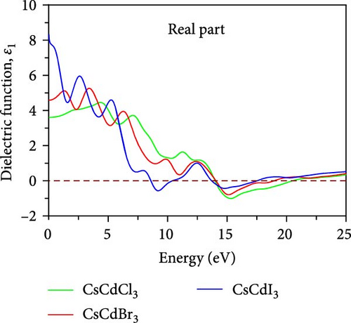
The magnitude of the static dielectric constant, ε1(0) is evaluated to be 3.61 for CsCdCl3, but when Br and I are used as substitutes for Cl, its values become 4.58 and 8.33, respectively. The value of ε1(0) slightly increases in the lower energy region for CsCdBr3 and CsCdCl3, but it sharply decreases in the lower energy region for CsCdI3. A vital measure for evaluating an optoelectronic device’s efficacy is the ε1(0). The charge carrier recombination rate probability is less in the substance with the greater dielectric constant [66]. Moreover, the metallic characteristics are indicated by the negative portion of the real dielectric constant.
The ε2(ω) is a very important parameter because the absorption characteristics of a material depend on it. Figure 7b shows the variation of ε2(ω) within the energy spanning from 0 eV up to 20 eV, within this limit, three significant peaks are observed for CsCdCl3 at about 5.3, 8.8, and 13.8 eV. In the case of CsCdBr3 major peaks are observed at 4.4, 7.15, and 10.2 eV, with an additional peak at 1.94 eV. Similar to CsCdBr3, major peaks appeared at 3.41, 6.03, and 8.52 eV for CsCdI3, with an additional peak at 1.01 eV. The peaks are found to shift towards the lower energy side when Br and I are used as substitutes for Cl. It is also found that CsCdI3 exhibits sharper peaks than the other two compounds.
The absorption coefficient, α plays a key role in choosing a material in various optoelectronic devices as well as solar cell usage. Figure 7c illustrates the change in α with respect to photon energy, where each compound exhibits three significant peaks in the 0–20 eV energy range. The peaks appeared at 5.56, 9.06, and 14.7 eV. However, it becomes apparent that these peaks migrate towards the lower energy side when Br and I are used as substitutes for Cl. CsCdBr3 exhibits major absorption peaks at 4.77, 8.39, and 14.7 eV, and one additional peak at 10.7 eV, whereas maximum peaks are observed in the UV region. CsCdI3 exhibits major peaks at 3.97, 6.94, and 14.4 eV, and two additional peaks at 1.29 eV and 9.02 eV, respectively. CsCdI3’s absorption edge begins from 0 eV, which also confirms the metallic nature of CsCdI3.Moreover, the absorption spectra cover the whole IR and the visible region. CsCdCl3 and CsCdBr3 exhibit higher peaks in the UV region. So, we can predict that they are suitable as UV detectors and efficient UV absorbers [66].
Photoconductivity, σ is a very crucial property of a material. It also refers to optical conductivity. The photoconductivity spectra of CsCdX3 are demonstrated in Figure 7d, which exhibits a comparable absorption spectra pattern. As seen in Figure 7d, the CsCdCl3, CsCdBr3, and CsCdI3 show the highest peak in the energy range of 13–14.5, 10–11.5, and 6–7 eV, respectively. The figure displays the maximum conductivity of these compounds is located within the UV area, and the peak shifted toward the lower energy area when Br and I replace Cl.
The reflectivity spectra plotted in Figure 7e demonstrate that very low reflectivity (0.096) is obtained for CsCdCl3 at 0 eV. But when Br and I are used as substitutes for Cl, the reflectivity increases by the amounts of 0.132 and 0.236, respectively. Further, CsCdI3 gives higher reflectivity in the IR region than CsCdCl3 and CsCdBr3. So, we can predict that CsCdI3 is a more suitable material for the IR reflector and photographic technology [67]. CsCdCl3, CsCdBr3, and CsCdI3 display the highest reflectivity in the energy range of 18–21 eV, 14–16 eV, and 8–10 eV, respectively. Thus, these compounds could potentially be employed as an effective covering material to minimize the effect of solar heating in the UV region [35]. Further, CsCdI3 is predicted to be used as a UV shielding material due to having good reflectivity in the UV range [35]. This compound also has good reflectivity in the visible range; hence, it might be used in a solar cell as a form of back reflector. Another noticeable information is that the highest reflectivity is obtained in the energy range when the real dielectric component has negative values.
Figure 7f depicts the refractive index spectrum, which shows that the highest peak appears at 0 eV, progressively decreasing with photon energy. CsCdX3 (X = Cl, Br, and I) exhibits the minimum refractive index value in the UV area and the highest in the IR region. Among the compounds, CsCdI3 exhibits a greater refractive index at 0 eV, so it can be utilized as a waveguide [68]. Further, CsCdI3 can be used as an ohmic contact in OLED and QLED [67] as it is metallic and shows a good refractive index at 0 eV.
4. Conclusion
Using DFT calculations, the optical, mechanical, electronic, and structural characteristics of CsCdX3 are examined here. It is found that the estimated lattice constants and the previously published values coincide quite well. Because Br and I have bigger atomic sizes than Cl, it becomes apparent that replacing Cl with Br and I leads to higher cell volumes and lattice constants. Additionally, the estimated formation energy as well as elastic constants support the mechanical and chemical stability of CsCdX3. Moreover, Poisson’s and also Pugh’s ratios validate CsCdX3’s ductility, which increases when Br and I are used as substitutes for Cl. Apart from its enhanced ductility, CsCdI3 has superior machinability. The band dispersion diagram further supports the metallic character of CsCdI3, suggesting that it is a desirable material for usage as structural support in various devices. The halogen size is inversely proportionate with the bandgap, as explained by the computed band structure. The band gap shrinks as halogen atomic size rises. It would be possible to employ CsCdX3 (Cl, Br) as UV absorbers and detectors due to its broad UV absorption coefficient. Moreover, CsCdI3 exhibits exceptional infrared reflectivity, making them appropriate for infrared reflectors. They may be used as waveguides because of their greater refractive index in the infrared range.
Ethics Statement
All the authors declare that the manuscript does not have studies on human subjects, human data or tissue, or animals.
Conflicts of Interest
The authors declare no conflicts of interest.
Author Contributions
Md. Al Momin, Md. Rafiqul Islam, Md. Amran Sarker, Md. Solayman, Razia Khan Sharme, Md. Rasidul Islam, and Sohail Ahmad involved in conceptualization, methodology, software, validation, formal analysis, visualization, investigation, data curation, writing original draft, and review and editing.
Funding
Research supported by: Deanship of Research and Graduate Studies at King Khalid University ∗ RGP2/415/45.
Acknowledgments
The authors extend their appreciation to the deanship of Research and Graduate Studies at King Khalid University for funding this work through Large Research Project under grant number RGP2/415/45.
Supporting Information
Additional supporting information can be found online in the Supporting Information section.
Open Research
Data Availability Statement
The data that support the findings of this study are available from the corresponding author upon reasonable request.


