A 28-GHz Vivaldi Array Antenna With Power Divider Structure for Achieving Wide Band and Gain Enhancement
Abstract
This article presents a planar Vivaldi array antenna based on a power divider structure. A half-loop defected ground structure (DGS) is performed to decrease the mutual coupling between antennas in the bottom layer of the substrate. The proposed Vivaldi antenna has a 1 × 8 power divided microstrip line structure and performs well in antenna gain and beam directivity. To validate the design, the proposed high-gain planar Vivaldi array antenna was manufactured, and the measured results were very similar to the simulated one. The size of the proposed antenna is 67 × 44 mm2, the application band is 25–27.3 GHz, and the measured peak gain is 12.6 dBi. The antenna is simulated with an electromagnetic power density (PD) of 28.5 W/m2 at 1 cm2 and 7.27 W/m2 at 4 cm2, which are in compliance with the FCC regulations. Therefore, this antenna is suitable for wearable devices and is applied to n257, n258, and n261.
1. Introduction
The communication industry has been developing rapidly in recent years, and the fifth generation (5G) mobile network communication technology is changing the way of life nowadays. To address the need for higher speeds and greater bandwidth in 5G networks, beam array antennas are used to offset the weakening of signals due to atmospheric losses [1–9]. The next generation of wireless terminal communications equipment is focused on the popularity of low-cost beamforming antennas. High-gain antennas and multiarray units are essential for satellite, point-to-point, and radar communication systems. Traditional reflectors and lenses can increase antenna gain and are relatively inexpensive to manufacture, but beam steering and steering can only be achieved through mechanical control.
As a widely used high-directivity broadband antenna structure, the Vivaldi antenna has wide bandwidth, great antenna gain and efficiency, low PCB manufacturing cost, and lightweight [10–15]. To achieve high gain and directional beam characteristics, an array antenna can be used to generate parallel directional radiation beams, resulting in the effects of beam aggregation and increased bandwidth. In a study by authors in [10], a new Vivaldi array antenna with enhanced heat dissipation was manufactured using 3D-printed circuit board technology. The Vivaldi antenna is fed by a substrate-integrated waveguide (SIW), and the finned metal structure of the array antenna produces good bandwidth through an electrically and thermally coordinated design.
The array antenna structure includes planar multilayer array structures [16–18] and planar single-layer array structures [19, 20]. The array antenna unit uses bow tie patches [21, 22] and Vivaldi antennas [1, 23–25], both of which can provide better gain in the horizontal radiation direction. Vivaldi antennas are mainly divided into five types, which are antennas with perforated lenses [26, 27], slotted cone antennas [17, 19, 23, 27, 28], and SIW (SIW-integrated slotted cone antennas [10, 20]. In [17], a miniaturized 1 × 8 array antenna is presented for 5G millimeter wave communication applications. The antenna structure uses eight pairs of Vivaldi plus metasurface (MS), so that the array antenna has good antenna gain and bandwidth. In [19], the quasi-Yagi slot array antenna is structured as a 1 × 8 slot antenna array to increase the half-power beam width (HPBW). The antenna radiation has a fan-shaped beam direction. The high-gain ultrawideband (UWB) Vivaldi antenna combined with a phase adjusting unit (PAU) from the literature [13]. With the PAU and flexible substrate, the Vivaldi antenna can produce three states: planar, inward, and outward bending to dynamically adjust the frequency. The Vivaldi periodic array antenna of the lens beamforming network (BFN) in the literature [17] uses a two-dimensional Luneburg lens to be the BFN (LL-BFN). An antenna feed port is created on the LL-BFN for feeding to an external circular antenna array, allowing for more flexible antenna radiation characteristics. The structure of the enhanced low–frequency gain Vivaldi antenna in the literature [28] contains a cone and a balun. The tapered slot is used to improve the low–frequency gain while serving as a radiating structure in the high band. In [29], the power distribution structure is used to eliminate common-mode noise, and the Vivaldi antenna and slotted line design allow one to improve the gain and demonstrate stable radiation performance at the applicable frequency.
The Vivaldi antenna is a widely used structure with advantages such as wide bandwidth, high antenna gain, high antenna efficiency, low side flap, compact size, stable radiation direction, and suitable for high band applications. To further improve the performance of Vivaldi antennas, in many studies, comb-shaped slot structures [30–32], maple-leaf symmetric maple leaf structures [16, 33–35], metal surface materials [29, 36–38], dielectric lenses [39], substrate composite waveguide structure [33], tapered slot structure [40, 41], and parasitic circuit [42] were used. In [30], a slotted Vivaldi antenna with five equal slots on the sides is used to improve the directivity of the antenna and to reduce the path loss and improve the antenna gain. In [29], the reconfigurable Yagi Vivaldi transmit array antenna (RTA) is made up of a microstrip Yagi antenna and a Vivaldi antenna. A metal cross–supersurface plane at the transmitter end of the antenna improves the wide-angle impedance matching (WAIM) of the antenna. In [34], the HM-Vivaldi antenna is made up of two half-radiating arms and two rows of metal vias. Radiating arms are used to increase the length of the current path, increasing the gain. In [38], the Vivaldi antenna with high gain and wide-bandwidth artificial material lens AML, etched with a symmetrical slot matrix in the flare, and the AML unit further improve the bandwidth and antenna gain. In [39], the high-gain wideband Vivaldi lens antenna consists of two orthogonal Vivaldi antennas. A spherical dielectric lens is placed at the top transmitting end to achieve a gain of more than 15 dBi. In [33], a wideband symmetrical Vivaldi antenna is used that utilizes a dual-ridged SIW (DRSIW) to achieve a lower cutoff frequency compared to a normal SIW.
This study proposes a Vivaldi array antenna design with a power divider structure. The antenna structure uses a general microstrip line power divider structure to design a 1 × 8 power divider array antenna for signal feeding. Eight comb-gap Vivaldi antennas are used at the antenna end to significantly increase the antenna gain and achieve beam convergence. To reduce the interaction between the bottom antennas, a semicircular defect ground structure is utilized in the ground plane, which can effectively inhibit radiation between the bottom antennas and add an elliptical metal element to the antenna top layer to increase the antenna gain. The simulations were performed using electromagnetic simulation software, and the antennas were fabricated, and the simulation and measurement results were very consistent.
2. Antenna Design and Working Mechanism
2.1. Vivaldi Design

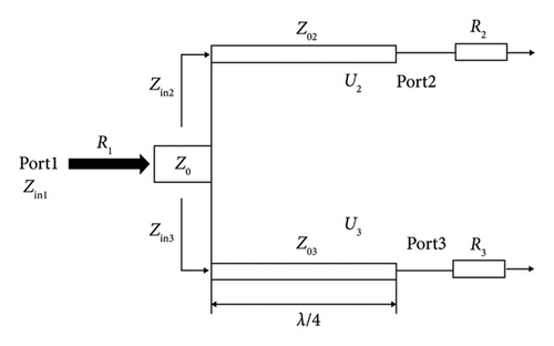
2.2. Power Divider Design
3. Vivaldi Array Design With Power Divider Structure
Then, we will use high-frequency electromagnetic simulation software to simulate the reflection coefficient change of the single-branch Vivaldi antenna and divide it into three antenna types for discussion, as shown in Figure 3. Type_1 is a common Vivaldi antenna with an underlying ground plane structure, and its reflection coefficient resonates at 26.5–27.4 GHz. The Type_2–etched half-ring defect structure on the antenna ground plane can produce a reflection coefficient in 25.5–27.5 GHz. Type_3 adds a comb-shaped slot structure to the top and bottom Vivaldi antennas, which can produce a reflection coefficient in the 25.5–29.5 GHz frequency band, which is 3.1 GHz higher than the application bandwidth of Type_1 and Type_2 in Figure 4. Figure 5 depicts the surface current simulation of a single Vivaldi antenna with three antenna types, and the simulation frequency point is set at 28 GHz. The surface current of the Type_1 feed port to the antenna end branch is weak, and the Type_2 branch has a stronger surface current than Type_1. Finally, in Type_3, it can be seen that there is a strong surface current from the antenna feed port to the antenna end, which indicates a good impedance match from the feed port to the Vivaldi antenna structure.

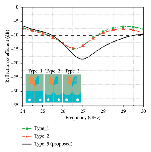
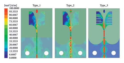
Figure 6 illustrates a one- to eight-power divider antenna. The structure is a comb-slotted Vivaldi antenna combined with a pseudo-element to enhance the gain. The ground plane etching semiring defect structure can decrease the coupling and enhance the radiation aggregation effect. The Vivaldi antenna with a comb-shaped slot structure in the bottom layer of the antenna and the Vivaldi antenna with a comb-shaped slot structure in the top layer generate a coupling effect with each other, allowing the bandwidth to reach 27.3–30 GHz. The detailed list of antenna parameters is presented in Table 1.
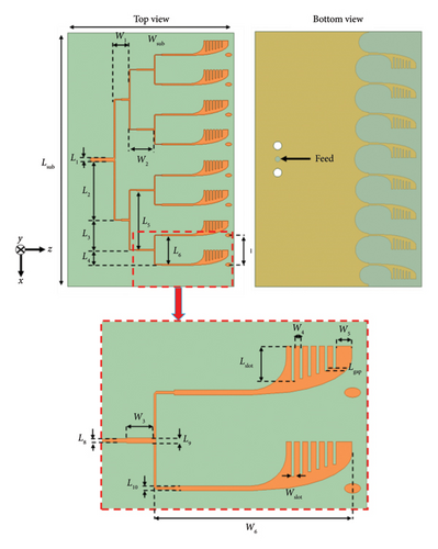
| Parameter | W1 | W2 | W3 | W4 | W5 |
| Value | 4 | 6.7 | 2.7 | 0.525 | 1.575 |
| Parameter | W6 | L1 | L2 | L3 | L4 |
| Value | 19.6 | 0.9 | 15.55 | 4 | 3.9 |
| Parameter | L5 | L6 | L7 | L8 | L9 |
| Value | 15.5 | 7.4 | 7.8 | 0.3 | 0.4 |
| Parameter | L10 | Wsub | Lsub | ||
| Value | 0.4 | 44 | 67 |
The antenna design process starts with a single-branch Vivaldi antenna for simulation, and then the antennas are connected in series in Figure 7. The single-branch Vivaldi antenna Ant_I of Figure 7(a) will generate a resonance frequency at 26–29 GHz, and the deepest resonance point is at 27 GHz.


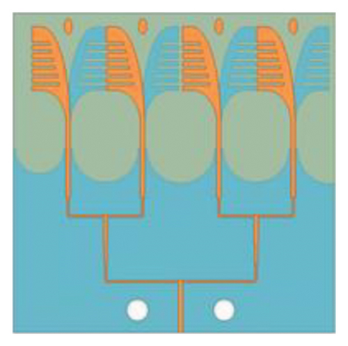

Ant_II of Figure 7(b) is a 1 × 2 Vivaldi array antenna with a resonant frequency of 27.9–29.9 GHz, and the deepest resonant frequency is at 29 GHz. Compared to the analog frequency band of Ant_I, it moves to a higher frequency as a whole. Ant_III of Figure 7(c) is a 1 × 4 Vivaldi array antenna with a resonance frequency range of 26–28.5 GHz, and the antenna has a deep resonance at 26.9 GHz. Finally, Ant_IV of Figure 7(d) is a 1 × 8 Vivaldi array antenna with a resonance frequency of 27.4–30 GHz, and the deepest resonance point appears at 28.3 GHz. Its frequency coverage is wider than that of Ant_I, Ant_II, and Ant_III, as shown in Figure 8.
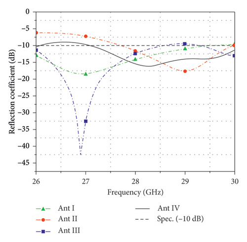
Figure 9 is a simulation of the antenna peak gain. The ANT_I is a single-branch Vivaldi antenna with a 7.5 dBi peak gain at 27 GHz. Ant_II has a peak gain of 9.5dBi at 29.5 GHz. Ant_III is simulated with a peak gain of 12 dBi at 30 GHz. Finally, Ant_IV has a 14.1 dBi peak gain of at 28.5 GHz. According to the above simulation results, the antenna gain can be improved by increasing the antenna elements.
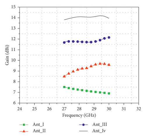
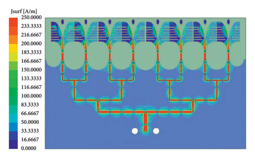
Figure 10 displays the simulated surface current results for the Vivaldi array antenna when arranged in a power divider configuration. The simulation frequency is set at 28 GHz. It can be observed that the current energy is evenly distributed from the feed-in end to the antenna end through a pair of eight power dividers composed of microstrip lines. This indicates that all transmission paths of the Vivaldi array antenna in this power divider have good impedance matching.
4. Specific Absorption Rate (SAR) Analysis
Table 2 summarizes the proposed restrictions of FCC [49], IEEE [47], and ICNIRP 2020 [46]. In the future, considering the application of prototype antennas to wearable arm parts, the impact of antenna radiation on the human body must be considered. So, this section uses the Sim4Life simulation software to draw the hand model and simulate the PD of the hand. Figure 11(a) is a schematic diagram of the distance between the antenna simulation and the arm of this section, which is 0 mm. Figure 11(b) is a hierarchical diagram of the tissue of the simulation software Sim4Life arm model.

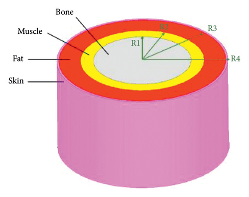
From inside to outside are bone, muscle, fat, and skin. The tissue radii of each layer are R1 equal 12 mm, R2 equal 35 mm, R3 equal 42 mm, and R4 equal 45 mm, and the detailed parameters are listed in Table 3.
| Tissue | εr | σ (S/m) | Density (kg/m3) |
|---|---|---|---|
| Skin | 37.26 | 1.85 | 1109 |
| Fat | 10.59 | 0.37 | 911 |
| Muscle | 51.81 | 2.30 | 1090.4 |
| Bone | 17.73 | 1.08 | 1178.3 |
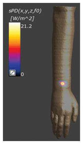
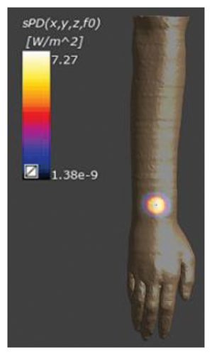
In the PD simulation, set the input power to 100 mW, set the distance between the antenna and the hand surface to 0 mm, and finally simulate the hand PD with a working frequency of 28 GHz. Figure 12 shows the results of the simulated frequency at 28 GHz. Its average area is 1 cm2 PD = 21.2 W/m2, and the average area is 4 cm2 PD = 7.27 W/m2, all of which comply with the PD specification of the US FCC. The average area is 4 cm2 PD < 10 W/m2, and the average area is 1 cm2 PD < 40 W/m2.
5. Experimental Results and Analysis
5.1. Impedance Bandwidth
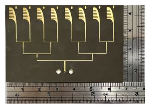
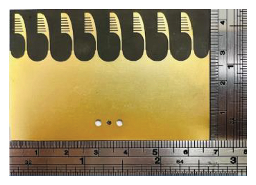
Figure 13 is the physical structure of the Vivaldi array antenna of the power divider, and the physical size is indicated by a ruler. The antenna size is 44 mm × 67 mm.
5.2. Radiation Properties
In Figure 14, the antenna is measured with an Agilent network analyzer (N5227A). The coaxial cable uses the model (WCA205-1.2M-65 GHz), the length is 120 cm, and the maximum supported frequency is 65 GHz. And short, open, and load (SOL) is used to calibrate before measurement, which can support a frequency of 10 MHz–67 GHz.
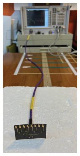
Figure 15 shows the simulation and measurement results of the reflection coefficient. The black curve resonates at 24.2–29.6 GHz below −10 dB. Two modes are generated at 24.8 GHz and 27.9 GHz, respectively. The measured blue curve resonates at an antenna frequency of 24.4–28.7 GHz. The simulation results of the difference caused by the actual addition of the end launch connector measurement should produce two modes at 24.8 GHz and 27.9 GHz, respectively. The measurement results will generate two modes at 25 GHz and 27.3 GHz, respectively.

The trend of simulation and measurement results is consistent and does not affect the application of this antenna in the millimeter wave frequency band. The measurement results have a more stable resonance.
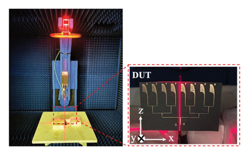
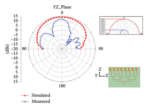
Vivaldi array antenna pattern measurements are performed in the MW6 millimeter-wave darkroom in a test environment supporting a frequency range of 24–42 GHz. Figure 16 consists of two photos, the right photo shows the object to be measured placed at the center of the cross-axis, and the left photo shows the MW6 millimeter wave darkroom measurement platform and the corresponding X-, Y-, and Z-axes. Figure 17 is a comparison of the results of the XZ plane radiation pattern. Since the MW6 millimeter wave anechoic chamber only supports 0 to 180 degree testing. Since the MW6 millimeter wave anechoic chamber only supports 0 to 180 degree testing, the method of measuring the XZ plane first takes the Y-axis as the center, the swing arm will measure from left to right, and the measurement angle ranges from 0 to 180 degrees. Therefore, the DUT is set at 0 degrees on the XZ plane. The peak gain of the main beam with the measurement frequency set at 28 GHz is 12.6 dBi, which is quite consistent with the simulation results. To compare the simulation of the YZ plane radiation pattern with the measurement results, the YZ plane measurement method first takes the X-axis as the center. The swing arm measures from front to back, and the measurement angle varies from 0 to 180 degrees. The peak gain of the measurement beam at 0 degrees on the YZ plane is 11.8 dBi, and the gain of the measurement result beam is relatively large. In Figure 18, there is a difference between the simulation and the measurement, which may be caused by the thinner bending of the plate.

6. Literature Comparison
The Vivaldi array antenna of the power divider proposed in this chapter is compared with international papers [1, 16–20] published in the past 3 years and is integrated in Table 4. The dimensions of the articles [16, 19, 20] are larger than those of the antennas in this article. The size of the paper [1, 17, 18] is smaller than the proposed antenna, but its bandwidth is narrower and the antenna gain is smaller. Compared to the working frequency of the literature [1, 16, 17, 19, 20], the proposed antenna works at 24.3–28.7 GHz and has a wider application frequency band. The literature [1, 17] has better antenna gain and FBW than using the same substrate. The antenna peak gain is 12.6 dBi and other literature works [1, 16–20] have better performance than the antenna gain. Therefore, the Vivaldi array antenna of the power divider in this chapter is very competitive.
| Ref. | Type | Size (mm2) | Frequency (GHz) | FBW (%) | Gain (dBi) | Substrate |
|---|---|---|---|---|---|---|
| [1] | 1 × 8 | 60 × 27 | 24.4–28.5 | 15.5 | 9.42–11.44 | Rogers 5880 |
| [16] | 1 × 4 | 60 × 135 | 27.5–28.5 | 3.57 | 8.16–9.46 | ISOLA, IS300MD |
| [17] | 1 × 8 | 28.5 × 60 | 24.15–28.5 | 16.52 | 9.2–11.9 | Rogers 5880 |
| [19] | 1 × 8 | 70 × 150 | 27.03–28.82 | 6.41 | 11.16 | Arlon/AD430 |
| [18] | 1 × 8 | 42.3 × 12.05 | 22.5–32.5 | 36.36 | 11.2 | Taconic RF-35 |
| [20] | 1 × 8 | 130 × 42 | 27.2–29.2 | 7.09 | 10.33 | Taconic RF-35 |
| Proposed | 1 × 8 | 67 × 44 | 24.3–28.7 | 16.6 | 12.6 | Rogers 5880 |
- Abbreviation: FBW ∗, fractional bandwidth.
7. Conclusion
This paper proposes a power divider structure for the Vivaldi array antenna. The antenna size is 44 mm × 67 mm, and the antenna top layer uses a one to eight power distribution structure with microstrip lines. At the end of the antenna, a dummy element is added to the Vivaldi antenna with a comb-shaped slot structure to increase the gain, and the bottom ground plane of the antenna uses an etched half-ring defected ground structure (DGS) to reduce the coupling between the bottom antennas. There is a Vivaldi comb-shaped slot structure antenna on the bottom layer and a top layer antenna to mutually generate the application frequency band. To consider the application of the Vivaldi array antenna of the power divider on the wearable, the simulation software Sim4Life is used to simulate the electromagnetic PD. And the hand model is drawn so that the distance between the object under test and the arm is 0 mm. The electromagnetic PD simulation is carried out in an environment with a frequency setting of 28 GHz and an input power of 100 mW. The simulation results show that the PD is 28.5 W/m2 in an average area of 1 cm2 and 7.27 W/m2 in an average area of 4 cm2, both of which meet the FCC regulations. Finally, the reflection coefficient measurement results are 24.4–28.7 GHz, and the beam peak gain is 12.6 dBi. The antenna in this paper has excellent performance in bandwidth and antenna gain and can be applied in the frequency bands n257, n258, and n261. By comparing the above measurement data with the literature over the past three years, it has a very competitive advantage in bandwidth and antenna gain. In this paper, the antenna can be improved in terms of size and gain. The multilayer board structure can be used to improve miniaturization. Adding a lens at the antenna front end can also increase the gain, in addition to enhancing the gain of the antenna element.
Conflicts of Interest
The authors declare no conflicts of interest.
Funding
This work was supported in part by the National Science and Technology Council, Taiwan, R.O.C. under Grant NSTC 113-2221-E-027-068- and in part by the National Taipei University of Technology–Vilnius Gediminas Technical University Joint Research Program (NTUT-VGTU) Joint Research Program under Grant NTUT-VGTU-113-03.
Acknowledgments
This work was supported in part by the National Science and Technology Council, Taiwan, R.O.C. under Grant NSTC 113-2221-E-027-068- and in part by the National Taipei University of Technology–Vilnius Gediminas Technical University Joint Research Program (NTUT-VGTU) Joint Research Program under Grant NTUT-VGTU-113-03.
Open Research
Data Availability Statement
The numerical and experimental data used to support the findings of this study are included within the article.


