Convex Optimization Algorithm for Maximizing Directivity of Conformal Array With DRR Constraint
Abstract
The inconsistency of conformal array elements poses a huge challenge to pattern synthesis. Based on convex optimization theory, this paper proposes a novel directivity pattern synthesis method. It can maximize the directivity of dual-polarized conformal arrays with a low dynamic range ratio (DRR). Firstly, the directivity function is presented under a dual-polarized conformal array. Then the pattern synthesis based on maximizing directivity is summarized as a multiconstraint optimization problem. In addition, the DRR constraint is introduced to control the weight range. By using Taylor expansion, the problem is transformed into a convex optimization problem and solved iteratively. Finally, simulation results demonstrate that the proposed method can effectively achieve a good directivity pattern with low sidelobe level (SLL) and low DRR.
1. Introduction
The conformal array antenna can maintain consistency with the surface shape of the carrier, expand the scanning range, and improve space utilization [1]. Hence, it is widely used in sonar, radar, communication, and other fields. However, the complex electromagnetic characteristics of the conformal array bring new challenges and difficulties to the pattern synthesis problem.
Pattern synthesis is an essential technique in the practical application of array antennas. Many scholars focus on this field, and many methods have been proposed in the past decades. Some methods are proposed based on planar arrays but can also be applied to different arrays. In [2], a proximal splitting is introduced to solve the constrained weighted least mean squares optimization problem based on alternating projection theory, which effectively solves the synthesis problem with weight constraints. In [3], a weight vector orthogonal decomposition method based on adaptive array theory is proposed, which can flexibly achieve pattern synthesis of any array. In [4], optimal weights are obtained through a conjugate gradient algorithm to minimize the error, which can control the sidelobe shape of arbitrary array patterns based on the method of least squares (MLS). In [5], the weighted least squares (WLS) cost function is used for pattern synthesis through an iterative process. Many global optimization methods, such as genetic algorithm (GA) [6], differential evolution (DE) [7], and particle swarm optimization (PSO) [8], have also been applied to array synthesis problems. Although these intelligent optimization methods are very flexible, they are time-consuming and may lead to random results.
With the development of convex optimization technology, it has been introduced into the pattern synthesis problem. The initial pattern synthesis problem is nonconvex and needs to be transformed into a convex problem by applying approximation methods [9]. In [10], the original power pattern optimization problem is iteratively linearized to several convex subproblems, which can be solved by second-order cone programming (SOCP). In [11], a combination of PSO and SOCP methods is proposed, which can optimize the element distribution of sparse conformal arrays and solve the optimal excitation through convex optimization. In [12], an array position refinement algorithm is proposed to achieve low peak sidelobe patterns by using high-order Taylor expansion. In [13], the auxiliary phase of the field pattern is introduced, and the original pattern synthesis problem is transformed into convex optimization problems with alternating iterations. In [14], the linear fractional semidefinite relaxation (LFSDR) method is used to achieve constant modulus synthesis, which can keep the excitation amplitude constant and achieve the desired patterns only by changing the phase.
The above algorithm primarily focuses on the pattern synthesis shape without considering the power gain of the array. However, in numerous scenarios, addressing the power gain within the pattern is necessary. Generally, the power gain of an array is approximately equal to its directivity. The gain of the array can be improved by maximizing its directivity, and the critical difficulty is to convert it into a convex function. In [15], the power gain pattern synthesis (PGPS) problem is transformed into a sequence of convex subproblems to maximize the minimum power gain in the main lobe area. In [16], the PGPS problem is reconstructed through linear optimization. This algorithm not only achieves the desired sidelobe level (SLL) but also exhibits a fast convergence speed. In [17], an auxiliary variable is introduced to relax the original PGPS problem into convex form and solve iteratively. It can obtain a lower SLL under a similar power gain in the main lobe as obtained by the shaped-beam pattern synthesis (SBPS) problem. However, in the above pattern synthesis methods, the dynamic range ratio (DRR) of weights is uncontrollable.
In practice, reducing DRR can not only simplify the design of array feeding networks but also better control the mutual coupling between antenna elements [18]. However, due to the nonconvex nature of DRR constraints, traditional convex optimization methods make it challenging to control DRR effectively and may cause power pattern distortion [19]. In [20], the DRR constraint is introduced to control the excitation in the PGPS problem. This problem is converted to a convex optimization problem by providing upper and lower limits on the excitation weights. However, due to the electromagnetic complexity of conformal arrays, the upper and lower limits of the provided weights may no longer be applicable, and the sidelobes may deteriorate.
Although some research exists on array directivity, there is little literature concerning the directivity of dual-polarized conformal arrays constrained by DRR. In this study, we propose a convex optimization method to maximize the directivity of the dual-polarized conformal array. At first, we give the directivity function of the dual-polarized conformal array. Then, a general multiconstraint optimization problem is proposed to maximize the directivity of the co-polarization main lobe while suppressing the sidelobe and cross-polarization level (XPL). After transforming the problem into a solvable convex optimization problem through linear transformation, DRR constraints are added to limit the weight range. Then, using Taylor expansion, the problem can be solved iteratively to approach the optimal solution of the original problem. Finally, simulation results show that the proposed method can reliably achieve a directivity pattern with low SLL and XPL at low DRR values.
2. The Directivity Pattern Synthesis of Dual-Polarized Conformal Array
2.1. Dual-Polarized Conformal Array
Consider a dual-polarized conformal antenna array consisting of N array elements as shown in Figure 1, (xi, yi, zi) is the coordinate of the ith element in the global Cartesian coordinate system O(x, y, z), and Oi(x′, y′, z′) is the local coordinate system of the ith element.
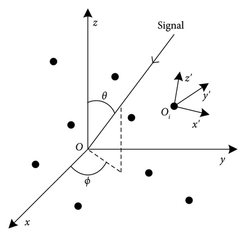
Eϕ(θ, ϕ) and Eθ(θ, ϕ) are assumed to be the co-polarization component and the cross-polarization component of the whole array pattern. Eiθ(θ, ϕ) and Eiϕ(θ, ϕ) are the contribution of the ith element to the θ-polarization component and ϕ-polarization component in the direction (θ, ϕ), respectively.
Note that a(θ, ϕ) is a matrix of size 2N × 2, which contains the steering vectors of two orthogonal polarization components.
2.2. Directivity Function of Dual-Polarized Conformal Array
From equation (9), it can be seen that B is a positive definite Hermitian matrix. The power gain of the array correlates directly with its directivity, and their ratio remains constant for the specific array.
2.3. The Dual-Polarized Directivity Pattern Synthesis Problem
The first constraint is used to maximize the minimum gain within the main lobe region. The second constraint ensures that the SLL does not exceed the given value. The third constraint ensures that the XPL does not exceed the given value. ρ and γ are the upper limits of the relative SLL and XPL. ΩM, ΩS, and ΩX are the regions of main lobe, sidelobe, and the cross-polarization, respectively.
2.4. Iterative Convex Optimization With DRR Constraint
2.4.1. Convex Approximation of Directivity Function
Although problem (11) eliminates the fraction constraints, there still exist second-order nonconvex constraints. The first inequality constraint is equivalent to . Since it is still nonconvex, its real part can be taken as an approximation to ensure convexity. In addition, the second and third constraints are already convex constraints, but for ease of calculation, they can be equivalently expressed in the form of modular constraints.
Note that B is a positive definite Hermitian matrix, so we have B = CHC. The last constraint of problem (11) can be written as wHC = 1. However, this constraint still requires convex relaxation; then the constraint can be relaxed to .
2.4.2. Convex Optimization Method With DRR Constraint
2.4.3. Taylor Expansion Iterative Optimization With DRR Constraint
In (20), the variable t needs to be constrained within a small range such as ‖t‖2 ≤ tmax, so that the higher-order term tHAϕ(θ, ϕ)t is small enough to be neglected.
Thus, t replaces w as the optimization variable, and the inequality constraints can be transformed to a convex form as w(i − 1)HAϕ(θ, ϕ)w(i − 1) + 2real(w(i − 1)HAϕ(θ, ϕ)t) ≥ g2.
A new weight vector can be obtained by finely adjusting the previous results. This adjustment dynamically changes upper and lower bound of the weight amplitude in each iteration, thereby strictly maintaining the controllable DRR of weights and ensuring the stability of the system.
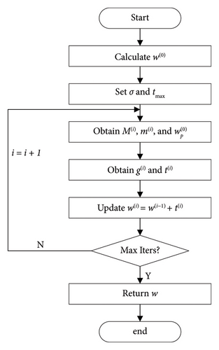
The initial weight vector can be obtained by solving problem (12). Then, considering the DRR constraints, the weight vector can be updated by solving problem (24). Then, the proposed iterative procedure can be operated as follows (see Algorithm 1).
Once the iteration number reaches its maximum value imax, the process terminates. The specific flowchart of the proposed method is shown in Figure 2.
3. Simulation Results
In this section, simulation experiments are presented to demonstrate the performance of the proposed method. All simulation experiments are carried out on a computer equipped with an i5-12500H, 2.5 GHz processor, and 16 GB of RAM. MATLAB R2022a is used as the simulation software.

3.1. The Pencil Beam of Arc Array
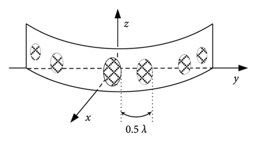
In this subsection, a 30-element arc array is used to achieve the pattern synthesis, and the spacing of adjacent elements is 0.5λ (see Figure 4).
Firstly, pencil beam is synthesized to verify the validity of the proposed method. The elevation angle θ is fixed at 90°, and the azimuth range is ϕ ∈ [−90°, 90°]. The main lobe area ΩM is ϕ0 = 0°, and the sidelobe area ΩS is ϕ ∈ [−90°, −7.5°] ∪ [7.5°, 90°]. The cross-polarization region ΩX is entire observation area. The upper bound parameters ρ and γ are both set to be −30 dB. The upper bound of step vector t is tmax = 0.1. The upper limit of DRR is σ = 5, and the initial DRR value of the method in [20] is set to be 10. The maximum number of iterations is imax = 30. The pattern synthesis results are shown in Figure 5. The distribution of the normalized weights amplitudes is shown in Figure 6.
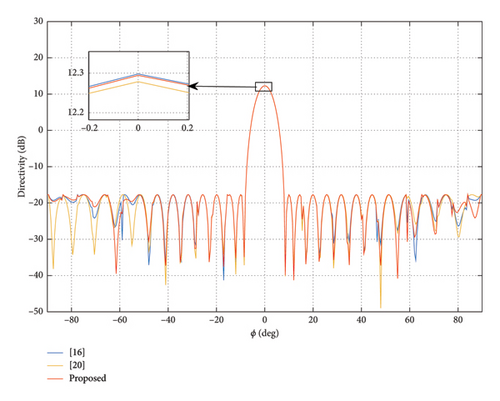
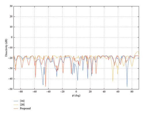
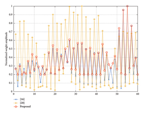
From Figure 5, we can see that the method in [20] cannot completely suppress the XPL. The directivity of the proposed method and the two comparison methods is 12.29, 12.30, and 12.28, respectively. They are almost the same. From Figure 6, we can see that the minimal weight value of the proposed method is significantly larger than that of the two comparison methods. Therefore, the DRR of the proposed method is lower than the DRR of comparison methods. The DRR value of the method in [16, 20] is 25.78 and 55.68. Meanwhile, the DRR value of the proposed method is 5. The final DRR value of the method in [20] exceeds the initial value. That is to say, we can obtain almost the same beam pattern under a much lower DRR than the comparison methods.
To further verify the impact of DRR, different DRR values are selected to verify the convergence of the proposed method. We set the upper bound of DRR to 5, 6, 7, and 8, respectively, while maintaining the same experimental conditions as the previous one. The main lobe peak directivity versus iteration number is shown in Figure 7.
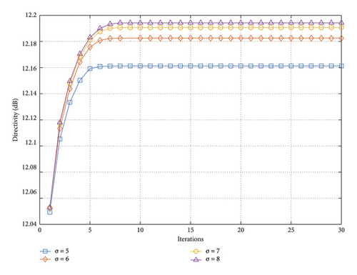
It can be seen that the proposed method converges quickly and obtains the optimized solution within 10 iterations. As the DRR increases, the directivity of the main lobe also increases. However, as the DRR value rises, the marginal utility of increasing the directivity of the main lobe decreases.
In order to assess the influence of tmax on the convergence of the proposed method, set tmax from 0.06 to 0.5 while fixing DRR at 5. Figure 8 shows that the directivity varies along with the increase of iterations.
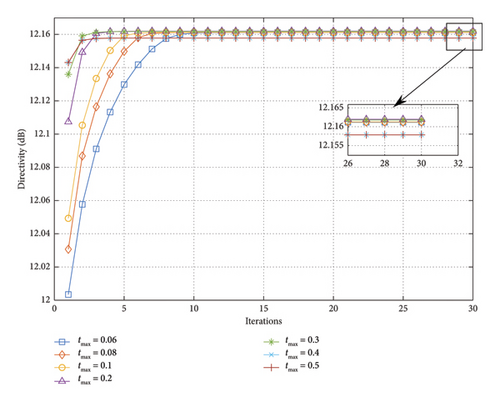
When tmax is less than 0.06, the solution space for t is too small. Hence, there are no solutions for problem (24). As shown in Figure 8, the proposed method exhibits good robustness when tmax varies within a certain range. Furthermore, a larger tmax results in a larger solution value for the first iteration and a faster convergence for the method. When the value of tmax exceeds 0.3, although convergence can be ultimately achieved, the final convergence value will decrease. Therefore, according to the experimental results, setting tmax to 0.1 is suitable.
3.2. The Flat-Top Beam of Arc Array
In this subsection, to further validate the capability of pattern synthesis of the proposed method with the same array as Section 3.1, this experiment is carried out to achieve the flat-top beam. The main lobe region and sidelobe region are ϕ ∈ [−17.5°, 17.5°] and ϕ ∈ [−90°, −25°] ∪ [25°, 90°], respectively. In this experiment, we still set tmax = 0.1, the upper bound of DRR value σ = 8 and imax = 50, and set the initial DRR to 20 of the method in [20]. When the upper bound of both ρ and γ is −30 dB, the obtained patterns are shown in Figure 9. The normalization amplitude of weights is shown in Figure 10.
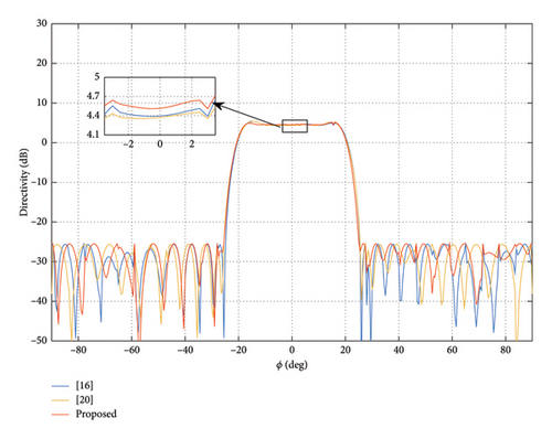
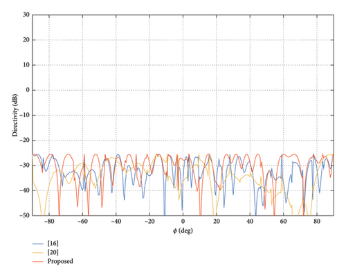

From the experiment result, it can be seen that our method can achieve a flat-top pattern with the lowest main lobe directivity (LMLD) of 4.52 dB and DRR = 8. The LMLD is only 4.39 dB, and DRR = 14.13 for the pattern is obtained by the method in [16]. The LMLD of the method in [20] is 4.37 dB, its dynamic range control fails again, and its final DRR value is 81.65. That is to say, the proposed method can achieve a higher main lobe directivity with a lower DRR.
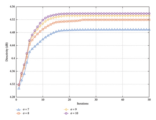
Similarly, in order to verify the impact of DRR on the proposed method, σ varies from 7 to 10. The other experimental conditions are the same as those in the above experiment. From Figure 11, we can see that the relationship between directivity and σ value still conforms to the law of diminishing marginal utility. However, the proposed method exhibits a slower convergence speed when achieving the flat-top beam than the pencil beam.
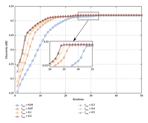
In this experiment, DRR is set to 8 to analyze the impact of tmax variations on the results. As illustrated in Figure 12, no matter how tmax changes, the final convergence result of the proposed method remains consistent. Specifically, as tmax increases, the speed of iteration convergence accelerates. However, when tmax exceeds 0.2, the acceleration is not significant. Therefore, setting tmax to 0.1 is also suitable.
3.3. The Flat-Top Beam of Cylindrical Array
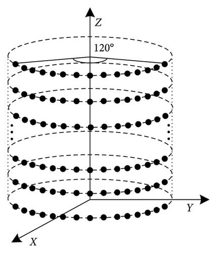
To verify the adaptability of the proposed algorithm in a 3D polarized conformal array, a 10 × 40 cylindrical array is adopted for this experiment. The spacing between neighboring elements is 0.5λ in each layer and the spacing between two layers is λ. The central angle of the cylinder is 120°, as shown in Figure 13.
In this experiment, (θ, ϕ) ∈ (60°, 120°) × (−30°, 30°) is the observation angle area, the main lobe region is , and the sidelobe region is , where ϕd = 0° and θd = 90°. The cross-polarization component of the pattern is suppressed in the entire observation region. In the experiment, the upper bound of DRR is set to 10 and tmax = 0.1, and the maximum number of iterations is 50. The upper limit of SLL and XPL is −20 dB. Figures 14, 15, and 16, respectively, represent the patterns of the proposed method, the method in [16], and the method in [20].

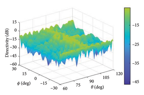
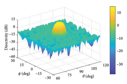

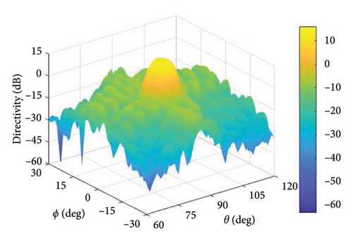
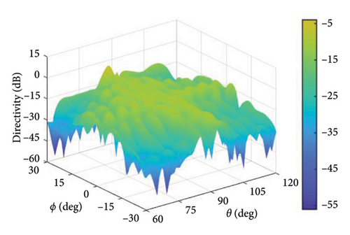
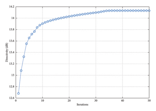
In the proposed method, the LMLD is 14.13 dB. The peak sidelobe directivity (PSLD) and peak cross-polarization directivity (PCRD) are −9.02 dB and −5.87 dB, respectively. In [16], the LMLD is only 12.38 dB, yet its DRR reaches 132.80. Similarly, in [20], the LMLD is 12.92 dB, and its DRR value is 307.30. The convergence curve in Figure 17 shows that the proposed method converges after 40 iterations.
4. Discussion
To effectively present the results between the proposed method and the two comparison methods, Table 1 outlines essential experimental data. This encompasses LMLD, PSLD, PCRD, SLL, XPL, and DRR values. For convenience, the peak directivity in the main lobe in Experiment A is also recorded as LMLD.
| LMLD (dB) | PSLD (dB) | PCRD (dB) | SLL (dB) | XPL (dB) | DRR | ||
|---|---|---|---|---|---|---|---|
| Experiment A | Proposed | 12.29 | −17.71 | −17.71 | −30 | −30 | 5 |
| Method in [16] | 12.30 | −17.70 | −17.70 | −30 | −30 | 25.78 | |
| Method in [20] | 12.28 | −17.71 | −13.72 | −29.99 | −26 | 55.68 | |
| Experiment B | Proposed | 4.52 | −25.48 | −25.48 | −30 | −30 | 8 |
| Method in [16] | 4.39 | −25.61 | −25.61 | −30 | −30 | 14.27 | |
| Method in [20] | 4.37 | −25.31 | −25.31 | −29.68 | −29.68 | 81.65 | |
| Experiment C | Proposed | 14.13 | −9.02 | −5.87 | −23.15 | −20 | 10 |
| Method in [16] | 12.39 | −7.91 | −7.91 | −20.3 | −20.3 | 132.80 | |
| Method in [20] | 12.92 | −7.07 | −3.97 | −19.99 | −16.89 | 307.30 | |
As shown in the above experiments, the proposed method can address the problem of maximizing the LMLD with a low DRR. Whether in 2D or 3D conditions, the proposed method can effectively achieve directivity pattern synthesis. More importantly, the proposed method significantly reduces the dynamic range of excitation amplitude when achieving almost the same pattern as the comparison methods. In the case of pencil beams, the directivity obtained through the proposed method is basically the same as the comparison methods, and their SLL and XPL can be suppressed to around −30 dB. However, the method in [20] does not effectively suppress XPL. For flat-top beams, the proposed method is applied to both arc array and cylindrical array, and the LMLD of the proposed method is higher than that of the two comparison methods. Moreover, except for the method in [20] that fails to suppress XPL in Experiment C completely, all SLL and XPL can reach the expected values. In all three cases, the DRR values of the proposed method are lower than those of the comparison methods. Although the convergence speed is slower in 3D synthesis than in 2D synthesis, the convergence of the proposed method can be guaranteed.
However, our method is only a convex approximation of the original problem and thus may retain some error compared to the original problem. On the other hand, although the proposed method exhibits outstanding convergence, it requires considerable computing time, especially in 3D pattern synthesis conditions. In the future, more efficient methods can be studied to reduce its computational complexity further.
5. Conclusions
This study proposes a directivity pattern synthesis method for a dual-polarized conformal array with DRR constraint based on convex optimization. The proposed method maximizes the minimum directivity of the main lobe and reduces the SLL and XPL with a low DRR. The directivity function of the dual-polarized conformal array is provided, and the pattern synthesis is formulated as an optimization problem. Taylor expansion is adopted, and the DRR constraint is converted to two convex constraints embedded in an iterative process to approach the optimal solution. Simulation experiments on different arrays and patterns show the adaptability and availability of the proposed method. Furthermore, the proposed method can achieve remarkable performance of the directivity pattern synthesis, even if the DRR remains within 10.
Conflicts of Interest
The authors declare no conflicts of interest.
Funding
The authors received no specific funding for this work.
Open Research
Data Availability Statement
The image data used to support the findings of this study are available from the corresponding author upon request.


