Comparative Study and Airspeed Sensitivity Analysis of Full-Wing Solar-Powered UAVs Using Rigid-Body, Multibody, and Rigid-Flexible Combo Models
Abstract
Solar-powered UAVs are characterized by large-scale, lightweight, and low airspeed, and changes in airspeed lead to wing deformation or stalling, which can easily induce serious flight accidents. A single dynamic model cannot accurately describe this feature, and this airspeed sensitivity can only be analyzed by integrating rigid-body, multirigid-body, and rigid-flexible combo models. This paper proposes a dynamic analysis method for a mixture of rigid-body, multirigid-body, and rigid-flexible combo models, considering the applicable airspeed ranges, computational costs, and structural deformation assumptions of the three models and comparing the differences of modes and responses at different airspeeds, and quantitatively analyzes the effects of airspeed on the motion, deformation, and coupling. The results show that appropriate increase of airspeed is beneficial to the stability of large-scale lightweight platforms, but when it is increased to more than two times the cruise speed, the structural deformation is coupled with the flight dynamic modes, leading to the deterioration of the overall dynamic response. Finally, a mixture of the three models at different airspeeds is proposed, which is necessary for future ultralarge-scale solar-powered UAVs.
1. Introduction
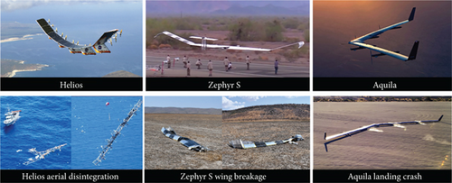
The solar-powered UAV is an innovative platform that integrates photovoltaic (PV) cell, battery, electronic speed control (ESC), motor, and propeller to achieve high energy efficiency and overcome the flight endurance limitations of electric UAV [1, 2]. This platform has broad application potential in both military and civilian fields [3–5] and is represented by Helios series, Zephyr series, Aquila series, and others [6]. On the other hand, the UAV is highly susceptible to wind interference due to its large scale, small wing loading, low airspeed, and narrow flight envelope [7, 8]. For instance, incidents such as the aerial disintegration of the Helios in 2003 due to gust interference [9], the landing crash of the Aquila in 2016 [10], and the wing breakage of the Zephyr S in 2019 due to gust interference [11], as illustrated in Figure 1, demonstrate this vulnerability.
The flight accidents show that (1) during the landing or low airspeed phase, strong winds interfere with the weak wind resistance of these UAVs, preventing them from maintaining attitude and trajectory stability; (2) aerodynamic loads increase with airspeed causing structural deformation and coupling with motion; and (3) inaccurate airspeed measurement led to control architecture based on airspeed feedback being unable to guarantee state stability. Solar-powered UAVs are extremely sensitive to airspeed while pursuing to maximize energy utilization, and we found similar problems when flying the full-wing solar-powered UAV shown in Figure 2. This UAV boasts excellent aerodynamic efficiency and maximizes the PV cell area by not having horizontal tail, vertical tail, ailerons, or rudder, but extremely low airspeed (9–13 m/s) and underinput control scheme make it challenging to precisely control airspeed and trajectory [12], which leads to its difficulty in achieving accurate landing control under wind disturbances.
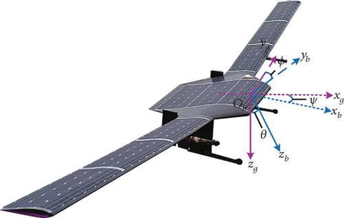
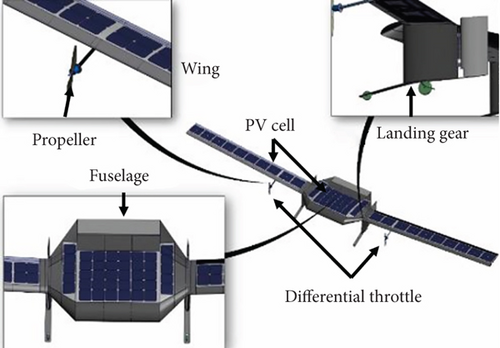
The easily deformed and rigid-flexible coupling of solar-powered UAVs present challenges for describing their dynamics using a single rigid or flexible body model. Ma, Zhu, and Zhou [13] conducted an analysis to identify the reasons behind the poor accuracy of taxiing trajectories of a full-wing UAV, determined the relationship between the uncertainty of model parameters in the 6-DOF equations and the control accuracy, and experimentally calibrated the aerodynamic and propeller model parameters. Hasan et al. [14] focused on the wind disturbance characteristics of large-scale solar-powered UAVs and noted that airspeed variations can cause structural deformations that impact motion modes. Benassi and Aquilini [15] highlighted changes in design requirements for stratospheric solar-powered UAVs and emphasized that structural dynamics need to be considered during takeoff and landing phases, even though they only account for 1% of the total flight time.
Meanwhile, solar-powered UAVs have a very limited mission payload capacity, and the combing multiple mesoscale UAVs into a superscale platform may be a viable option, but it also poses a challenge to the accuracy of dynamic modeling and analysis. Wu et al. [16] investigated the impact of connection on drag of multibody-connected solar-powered UAV, highlighting the sensitivity of endurance to this characteristic. Zhu and Zhou [17] summarized the advantages of modular integration, multidegree-of-freedom deformation, and long endurance of the multibody-connected UAV through the combination of three fixed-wing UAVs. Dou and Zhou [18] developed a drop-deployment process for folding solar-powered UAVs based on Lagrange’s equation and identified differences between flexible and rigid bodies during deployment. Li et al. [19] studied the sensitivity of design parameters of the solar panels of satellite folding array PV cell deployment mechanism and analyzed the effects of locking time, stabilization time, contact force, and clearance on the rigid-flexible coupled system from the perspective of multibody dynamics.
In the structural and flight dynamic modeling of solar-powered UAVs, multirigid body, flexible beam, and finite element models have different advantages, and the flexible beam theory is widely used for its ability to take into account the dynamic characteristics and computational cost, and the representatives are displacement formulation [20], intrinsic formulation [21–23], or strain formulation [24–26]. Voß et al. [27] used an intrinsic beam model to analyze the challenges of flight envelope boundaries on structural safety and presented the changing weight of aeroelastic analysis in the design of solar-powered UAVs. Zúñiga, Souza, and Góes [28] proposed a beam model based on a combination of modal and flight dynamics to study the flight-structure coupling characteristics of solar-powered UAVs, emphasizing the airspeed changes on structural safety. Hu et al. [29] proposed a method to calibrate a rigid-body flight dynamic model using flexible beam model for drop-in solar-powered UAVs. Bras, Warwich, and Suleman [30] also proposed a strain beam modal experiment-flight synthesis, pointing out the need for multidisciplinary optimal design of UAVs, emphasizing the potential impact of increased airspeed.
The above research points out the sensitivity of solar-powered UAVs to airspeed but has not been quantitatively analyzed to explain the effects of airspeed changes on dynamic stability, structural safety, and system energy. Therefore, this paper establishes different dynamic models to analyze the motion and deformation of a full-wing solar-powered UAV and illustrates how it is affected by airspeed changes, including the effect of airspeed decrease on stability, and the changes in structural deformation and motion characteristics due to airspeed increase, to provide guidance for its safe operation. The main contributions of this paper are presented as follows: (1) Rigid-body, multirigid-body, and rigid-flexible combo models of the full-wing solar-powered UAV are established to analyze the differences in dynamics with airspeed as a variable. (2) A method for analyzing the airspeed sensitivity of large-scale lightweight aircraft that integrates three models is proposed. (3) Factors that must be considered by solar-powered UAVs in different airspeeds are identified to provide guidance for the safe flight.
The paper is organized as follows: Section 2 establishes a rigid-body 6-DOF dynamic model and analyzes the modal characteristics of different airspeeds. Section 3 establishes the multirigid-body dynamic model and analyzes the effect of dihedral angle equivalent deformation for different airspeeds. Section 4 establishes the strain beam dynamic model to analyze the structural instability phenomenon for larger airspeed increase. Section 5 discusses the airspeed thresholds of the three dynamic models. Section 6 outlines the conclusions and future work.
2. Rigid-Body Dynamic Modeling and Airspeed Sensitivity Analysis
The full-wing solar-powered UAV can be regarded as a rigid body at cruise speed range and modeled using 6-DOF equations. This paper compares the difference in dynamics between the full-wing configuration and the normal configuration at different airspeed conditions.
2.1. 6-DOF Dynamic Equations
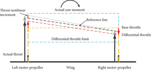
However, the thrust of the motor-propeller system is not linearly related to the throttle command. This results in a yaw moment that is generated by the differential throttle and is not only related to the differential throttle command δdT but also to the base throttle δT. As the full-wing configuration lacks ailerons, the UAV is more prone to sideslip angle during control. However, the yaw moment generated by the differential throttle is related not only to its command but also to the base throttle command, and the thrust generated by the motor-propeller is nonlinear with the throttle, resulting in the UAV being more susceptible to sideslip during lateral control. Therefore, to achieve the same control effect as the normal configuration, the control system of the full-wing relies more on the accuracy of the thrust model.
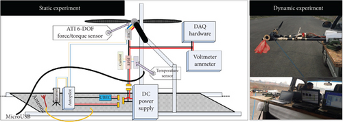
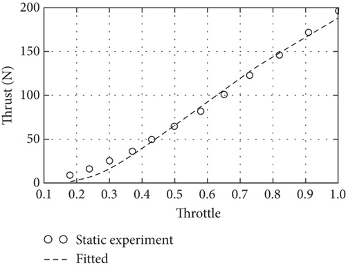
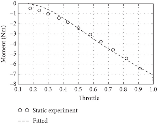
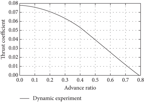
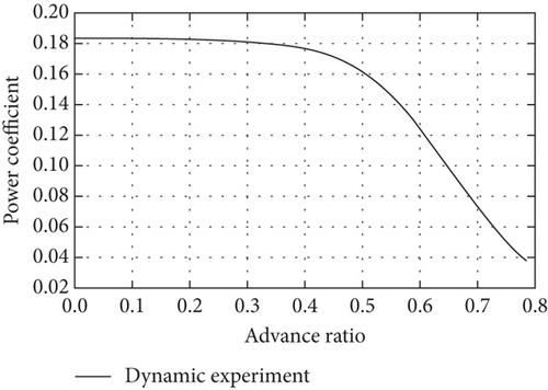
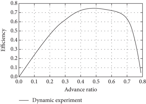
In the static experiment in Figure 4, the system is fixed on a table, and the autopilot sends a throttle command while the power is measured by the voltage-current sensor, and the propeller thrust and torque are measured using an Industrial Automation Company (ATI) Gamma 6-DOF force/torque sensor. Then, in the dynamic experiment, the motor-propeller system is fixed onto a car, and different throttle commands are input with speed intervals ranging from 10 to 50 km/h, and the dynamic power, propeller thrust, and torque are measured by the sensors. The static experimental results in Figures 5(a) and 5(b) are used as initial values for the dynamic experiment, and the dynamic test points are set according to a 10 km/h speed interval to obtain the experimental results of advance ratio to thrust, power, and efficiency at different speeds are shown in Figures 5(c), 5(d), and 5(e). Finally, the fitted model is used to calibrate the parameters of the motor propeller.
2.2. Modal Analysis of Different Airspeeds
Then, the 6-DOF equation is linearized to compare the modal characteristics of the full-wing configuration with the same wingspan of the normal configuration at different airspeeds, where the full-wing uses differential throttle and the normal uses rudder for lateral control, shown in Figure 6.
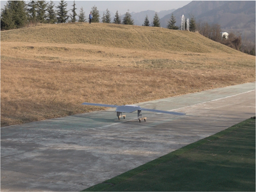
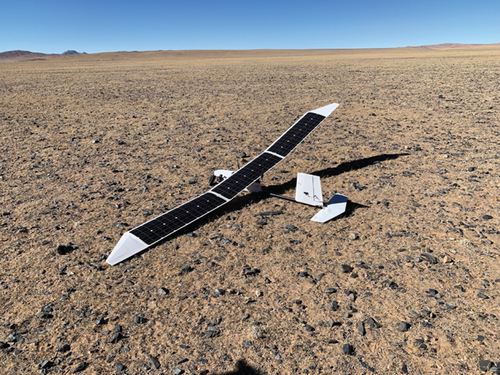
Table 1 lists the basic parameters of the two lightweight UAVs, both with aspect ratios close to 11 and surface densities of 4.5 and 3.1 kg/m2, respectively. The main weight of the full-wing is concentrated in the fuselage, the weight ratio of the wing to the fuselage is 1 : 3, and the longitudinal and heading moments of inertia are close to each other, with the ratio to the lateral moment of inertia of 1 : 13.5. The normal configuration has a tail with throttle, elevator, and rudder as control inputs, the overall weight is concentrated on the wing with a wing-to-fuselage weight ratio of 1 : 1.7, and the ratio of longitudinal and lateral moments of inertia is 1 : 4.7.
| Wingspan (m) | Chord (m) | Weight (kg) | Ix(kgm2) | Iy(kgm2) | Iz(kgm2) | Ixz(kgm2) | |
|---|---|---|---|---|---|---|---|
| Full-wing | 3.5 | 0.33 | 4.0 | 1.11 | 0.08 | 1.12 | −0.003 |
| Normal | 3.2 | 0.29 | 2.9 | 0.96 | 0.21 | 1.13 | −0.03 |
2.2.1. Longitudinal Motion Modal Analysis
The modal distribution is calculated under various airspeed conditions, and the effect of airspeed variation on motion characteristics is analyzed. The result shows that for the full-wing configuration, it is crucial to focus on the adverse effects when airspeed decreases, and Table 2 shows the longitudinal aerodynamic derivatives of the two UAV configurations for reference.
| CDα | CLα | Cmα | CLq | Cmq | −Cmα/CLα | |||
|---|---|---|---|---|---|---|---|---|
| Full-wing | 0.2408 | 4.7860 | −0.1941 | 4.0524 | −0.8378 | 0.422 | −0.3211 | 4.05% |
| Normal | 0.2340 | 5.2525 | −0.7747 | 6.8204 | −7.6343 | 0.309 | −0.9425 | 14.8% |
| Short-period mode | Phugoid mode | |||||
|---|---|---|---|---|---|---|
| Eigenvalue | Damping ratio | Nature frequency | Eigenvalue | Damping ratio | Nature frequency | |
| Full-wing | −6.7 ± 7.89i | 0.63 | 10.21 | −0.007 ± 0.09i | 0.02 | 0.79 |
| Normal | −8.10 ± 5.71i | 0.82 | 9.9 | −0.039 ± 0.84i | 0.05 | 0.84 |
- Note: i means the complex number.
Due to the absence of the tail, the full-wing has a shorter longitudinal control length; hence, Cmα and Cmq are smaller than those of the normal. The damping ratio of the short-period mode of the full-wing is 0.63, lower than that of the normal at 0.82, and the natural frequency of the short-period mode of the full-wing is 10.21, higher than that of the normal at 9.9. The result shows that the full-wing has inferior pitching motion suppression capabilities, but both two exhibit similar characteristics in heaving motion for the phugoid mode. Then, the longitudinal modes of the two are compared within the range of 9–13 m/s, and Figure 7 displays the eigenroot trajectory where the arrow direction represents the increase of airspeed.
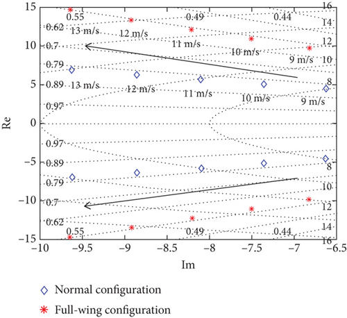
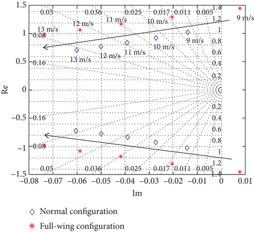
Figure 7(a) shows that the short-period mode frequencies of both increase with increasing airspeed and the damping ratio remains constant, and Figure 7(b) shows that the phugoid mode of the full-wing changes from unstable to stable with increasing airspeed, while the normal remains stable. Therefore, the longitudinal modes of both improve with increasing airspeed. However, at this wingspan condition, the phugoid mode of the full-wing becomes unstable with the airspeed less than 9 m/s, while the normal approaches neutral stability, so special attention must be paid to the stability and dynamic response of solar-powered UAVs at low airspeed conditions.
2.2.2. Lateral Motion Modal Analysis
The lateral aerodynamic derivatives of the two UAVs are shown in Table 4. The lateral static stability derivative Clβ and damping Clp of the full-wing are close to the normal, but the heading static stability derivative Cnβ and damping Cnr are significantly smaller, so the lateral stability of the two is close, but the heading stability of the full-wing is worse. The full-wing employs two vertical stabilization surfaces for stabilization and landing gear purposes, and its side force coefficient CY and roll moment coefficient Cl are close to those of the normal, but the tailless design means that the heading motion is close to neutral stabilization, causing it to be more sensitive to sideslip.
| CYβ | Clβ | Cnβ | Clp | Cnp | Clr | Cnr | |
|---|---|---|---|---|---|---|---|
| Full-wing | −0.263 | −0.114 | 0.005 | −0.559 | −0.050 | 0.145 | −0.004 |
| Normal | −0.313 | −0.168 | 0.016 | −0.602 | −0.0347 | 0.1196 | −0.021 |
| Roll | Dutch roll | Spiral | |||
|---|---|---|---|---|---|
| Eigenvalue | Eigenvalue | Damping ratio | Nature frequency | Eigenvalue | |
| Full-wing | −24.2 | −0.25 ± 1.57i | 0.16 | 1.59 | −0.11 |
| Normal | −13.1 | −0.28 ± 2.26i | 0.122 | 2.27 | −0.53 |
- Note: i means the complex number.
Both two configurations used a large aspect ratio upper dihedral angle wing design with stable roll and dutch roll modal characteristics, but the weak heading stability of the full-wing leads to a spiral mode close to neutral stability. Then, the effect of airspeed variations on lateral stability is analyzed by comparing the lateral eigenroot trajectories of the two in the 9–13 m/s, as shown in Figure 8.
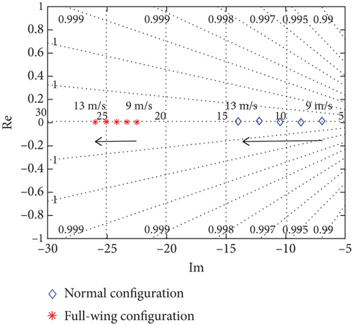
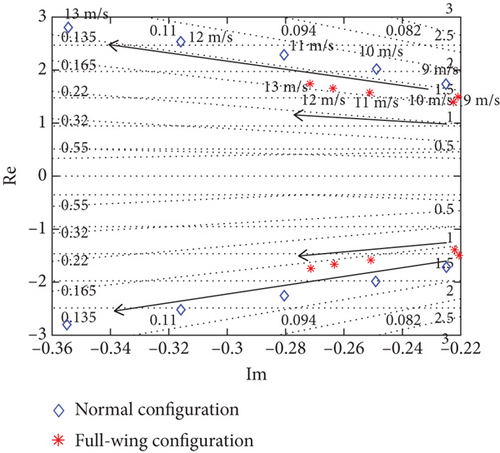
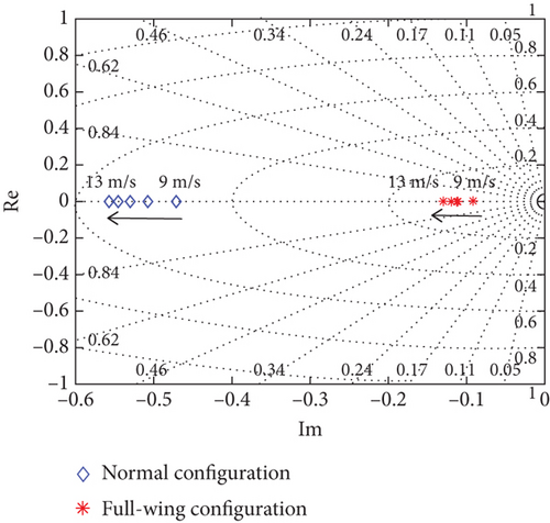
Figures 8(a) and 8(b) shows that an increase in airspeed makes the lateral modes better, with both two having improved stability for the roll and dutch roll modes. However, as the airspeed decreases, the stability change is more pronounced for the full-wing, with the damping ratio of dutch roll mode decreasing and the spiral mode approaching neutral stability, as shown in Figure 8(c). Both longitudinal and lateral modes described above show that the low-speed stability of the full-wing is much lower than that of the normal.
In lateral control, rudder is used for the normal and differential throttle is used for the full-wing, both of which generate sideslip first and then rely on asymmetric lift of the wing to generate roll moment for attitude control. The rudder control produces a yaw moment proportional to the dynamic pressure, while the differential throttle produces a nonlinear yaw moment influenced by the base throttle command and differential throttle limit. Therefore, for the full-wing, when airspeed changes, the base throttle command also changes and the yaw moment generated by the same differential throttle command changes as well. Moreover, the differential throttle control also causes a change in total thrust, leading to changes in airspeed due to thrust changes obtained while generating yaw moment. The weak heading stability of the full-wing with the differential throttle control mode makes the difficulty of both stable airspeed and precise heading control greater than that of the normal.
3. Multirigid-Body Dynamic Modeling and Airspeed Sensitivity Analysis
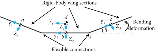
Increasing airspeed is beneficial to flight stability and control, but the increased aerodynamic forces cause deformation of the lightweight UAV. Multiple flights of the full-wing solar-powered UAV show that the wing is prone to deformation under wind interference, and the deformation amplitude increases with airspeed, while the fuselage and vertical stability surfaces are almost unaffected [25]. The 6-DOF rigid-body model is unable to consider the deformation and needs to be extended. For this reason, the full-wing is considered as a system composed of multiple rigid bodies, and the deformation is expressed by a flexible joint at the connection between the wing and the fuselage. Then, the UAV in Figure 2 can be regarded as a multirigid-body system composed of three rigid-body wing segments and two flexible connection points, as shown in Figure 9. To simplify model analysis complexity, only the longitudinal dynamics are considered.
3.1. Multibody Dynamic Equations Based on Flexible Connections
3.2. Dihedral Angle Equivalent Deformation Analysis
The multirigid-body model is based on the rigid-body model with an dihedral angle equivalent deformation, where an increase in airspeed causes an increase in the dihedral angle, resulting in a change in the mode and dynamic response. In order to analyze the coupling characteristics, a full-wing solar-powered UAV with a wingspan 7 m (Figure 2), chord length 0.4 m, and weight 15 kg is taken as an example for trimming analysis and nonlinear simulation. Then, Equation (21) is expressed in the form of a state space, with the state adding dihedral angle Δη and its rate over the rigid-body model, and the control input including elevator δe and thrust T. The trimming calculation is carried out at an altitude of 500 m, an airspeed of 12 m/s, a pitch angle and pitch angular velocity of zero, and a dihedral angle range of 0–20 degrees, as shown in Figure 10.
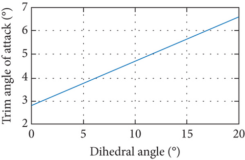

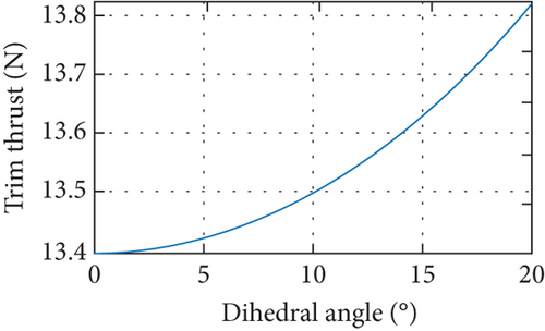
As the dihedral angle increases, the wingspan projection length shortens. Under equilibrium conditions, Figure 10(a) shows that the trimmed angle of attack increases from 2.8 to 6.6 degrees; Figure 10(b) illustrates that the trimmed elevator command is between −1 and 2.5 degrees; and Figure 10(c) indicates that the trimmed thrust remains stable from 13.4 to 13.8 N. When the increase in airspeed causes an increase in aerodynamic force, the dihedral angle increases and the trim angle of attack increases, while the elevator and throttle commands remain almost constant.
3.2.1. Dihedral Angle Modal Analysis
In order to analyze the effect of the increase in airspeed, the trimmed dihedral angle, elevator, and thrust are calculated for airspeed of 9, 12, and 15 m/s, respectively, at an angle of attack of 2.8 degrees, as shown in Figure 11.
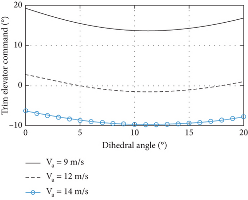
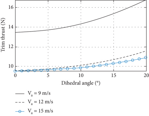
As airspeed increases, the trimmed elevator decreases from 15 degrees to −10 degrees, and the thrust decreases from 15 to 10 N. When the dihedral angle increases from 0 to 10 degrees, the trimmed elevator is minimum, and the thrust increases only slightly, the small deformation is favorable for trimming performance. Then, stability analysis of the system is performed at different airspeeds and dihedral angles, with total seven eigenroots, including height, dihedral angle, and its rate as three real roots, in addition to short period and phugoid of the rigid body as two pairs of conjugate complex roots, as shown in Figure 12.
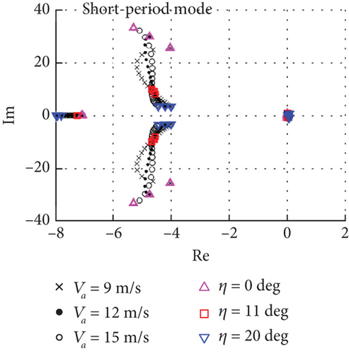
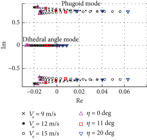
Figure 12(a) shows the distribution of short-period and altitude modes. Under the same airspeed conditions, the stability of the short-period mode is unchanged, and its natural frequency decreases with the increase of dihedral angle; under the same dihedral angle conditions, its stability and natural frequency of the 0-degree dihedral angle increase with the increase of the airspeed, but the modal characteristics of the 11-degree and 20-degree dihedral angles are almost unchanged. Therefore, the small increase in dihedral angle due to the increase in airspeed is favorable to the short-period mode, and it is almost unchanged after the dihedral angle exceeds 10 degrees. Figure 12(b) illustrates the distribution of phugoid and dihedral angle modes, where both two tend to be unstable as the dihedral angle increases. With the increase of airspeed, the phugoid mode for 0-degree dihedral angle remains stable, similar to Figure 7(b). However, the mode tends to be unstable at 11-degree and 20-degree dihedral angles, and the phugoid mode remains stable in the rigid-body model without considering the deformation, but in the multirigid-body model, the dihedral angle increases to more than 11 degrees with increasing airspeed, it approaches neutral stability. Although the stability and natural frequency of the short-period mode becomes slightly better with increasing airspeed, the phugoid mode couples with the dihedral angle mode leading to the final stability decrease, which is different from the rigid-body model.
3.2.2. Static and Dynamic Simulation Analysis
In order to verify the accuracy of the modal analysis, static and dynamic simulations of the multirigid-body dynamic model were performed under different airspeed conditions. The static simulation fixes the UAV and analyzes the relationship between the wind speed increase and the wing deformation. Considering the symmetry of the UAV in the longitudinal analysis, the half-wingspan dihedral angle and wingtip displacement are shown in Figure 13.
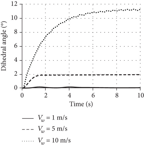
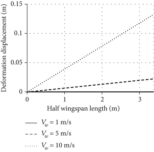
When the wind speed increases to 5 m/s, the dihedral angle increases to 2 degrees with a deformation displacement of 0.1 m, with a stable state response. However, when the wind speed increases to 10 m/s, the dihedral angle increases to 11 degrees and the deformation displacement reaches 0.6 m, and the dihedral angle appears to be slight oscillating, which will cause it to oscillate and disperse if the wind speed increases further, and this feature is consistent with Figure 12(b).
The dynamic simulation is used to analyze the effect of dihedral angle on motion with increasing airspeed in a multirigid-body model, in which the initial conditions are 500 m altitude, 12 m/s airspeed, zero pitch angle, and pitch angular velocity, and the differences in the response of the motion parameters are compared under the wind speed conditions of 1–11 m/s.
Figure 14 shows that the dihedral angle is stable at 0.05, 0.5, and 2 degrees with a convergence time of 2 s, and the airspeed, altitude, angle of attack, and pitch angle remain stable under 1, 5, and 10 m/s wind speed conditions. When the wind speed increases slightly, the dihedral angle in Figure 14(f) increases slowly and the state response is almost unchanged. When the deformation is caused by the increase of wind speed becomes more obvious, for example, the dihedral angle is larger than 5 degrees, the pitch angular velocity in Figure 14(c) is the first to oscillate, and its amplitude and convergence time also increase, and then, it converges as the dihedral angle is converged to stable. This shows that the wing deformation caused by the airspeed increase will be coupled with the motion, which makes the angular velocity oscillate first, and the stability of other states is also related to the deformation amplitude.
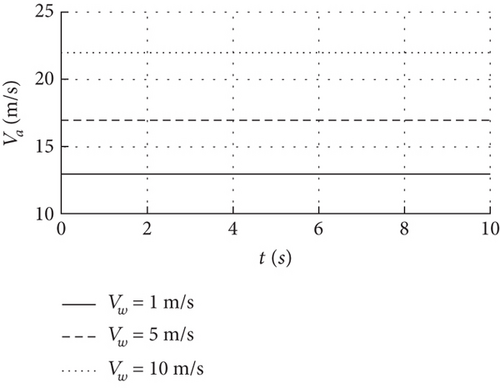
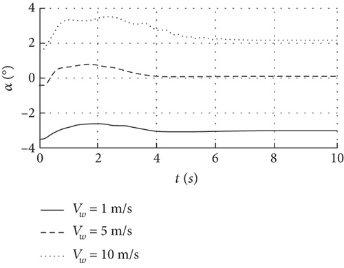
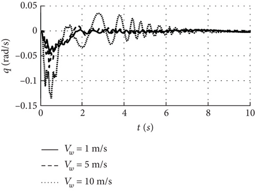
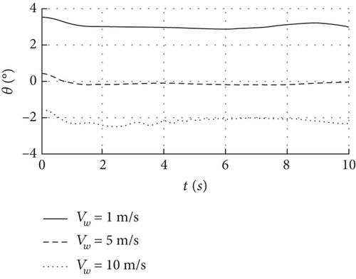
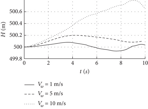

Specifically for the full-wing solar-powered UAV with wingspan 7 m, it can still be considered as a rigid body when the dihedral angle increase is less than 0.5 degrees at wind speeds below 5 m/s. However, when the wind speed is close to 10 m/s, the dihedral and phugoid modes are close to the neutral stability, the pitch angular velocity oscillates after the dihedral angle exceeds 5 degrees, and the response of the state parameters in this case is different from that of the rigid body. Therefore, the dynamic model must take into account the effects of structural deformation.
4. Rigid-Flexible Combo Model and Airspeed Sensitivity Analysis
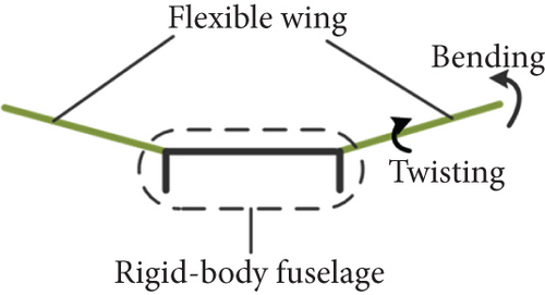
The multirigid-body model with dihedral angles for equivalent deformation is sufficient for small bending of the wing, but during upwind flight of a solar-powered UAV, the airspeed increase is further increased making the coupling between motion and deformation also increase, the deformation is more complex, and the model is no longer applicable. At this moment, it is appropriate to characterize the wing by a flexible beam and the fuselage by a rigid body, and then, the full-wing solar-powered UAV can be considered as a rigid-flexible combo model as shown in Figure 15.
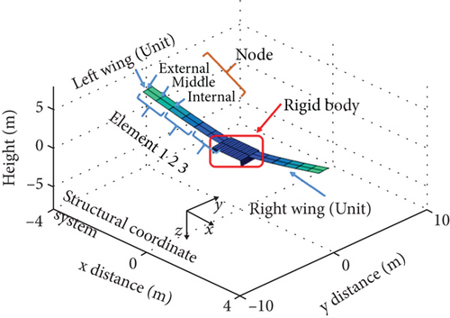
4.1. Structural Dynamic Equations Based on Strain Beams
In order to analyze the coupling of the large wing deformation and motion caused by the increase of airspeed, the static and dynamic simulations of the rigid-flexible combo model are also performed. Let N represent the number of structural nodes, the kinetic equations consist of 4 N second-order difference equations, the dynamic equations consist of 12 first-order equations, the aerodynamic model is composed of 3N × NA first-order equations, the thrust model consists of 5 first-order equations, and the generalized force and damping matrix couples the strain and displacement. Therefore, a freezing coupling term is used for the preliminary analysis of the dynamic characteristics over a large airspeed range, and then, the coupling term is updated in real time for the accurate analysis of the fluttering speed to balance the computational cost and accuracy.
4.2. Motion-Deformation Coupling Influence Analysis
Firstly, the trimming under different airspeed conditions is carried out to analyze the static deformation of the wing, and then, the nonlinear simulation of the model is carried out with the elevator as the disturbance to analyze the coupling of the wing deformation and the motion, and finally, the applicable airspeed threshold of the model is determined.
4.2.1. Trimming Analysis
- 1.
Assume that the UAV has not been deformed, ε = 0.
- 2.
Calculate the trimmed state according to the motion balance assumption, .
- 3.
Calculate the static deformation according to the deformation balance assumption, .
- 4.
Return to Step 2 until both motion and deformation conditions are valid, and ε = 0.
In order to analyze the coupling of large deformations and motions of the full-wing configuration, the pathfinder UAV [34] with a wingspan 36 m and a chord length 1 m is used as an example. Then, an altitude 20 km, an airspeed 16.7 m/s, and an angle of attack zero are the initial conditions for trimming, the iterative convergence process is presented in Figure 16, and the control input converges after 6 s, with the trimmed pitch angle, elevator, and throttle of 4.2 degrees, −11 degrees, and 0.57.
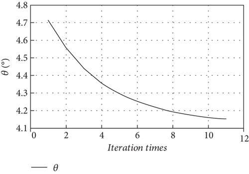
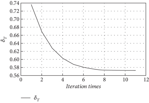
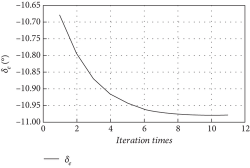
Figure 17 compares the actual deformation of the wing during flight with the static deformation of the wing of the combo model, and the static deformation of the trimming is consistent with those observed in real flight. It can be seen that the fuselage does not undergo any significant deformation, while the wing undergoes an upward bending deformation that gradually increases from the inside to the outside. The maximum deformation displacement is 2.1 m at the wingtip shown in Figure 17(b), and the deflection accounts for 13% of the half wingspan, which corresponds to a dihedral angle of 6.6 degrees.
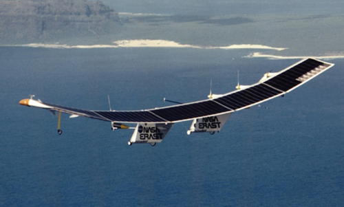
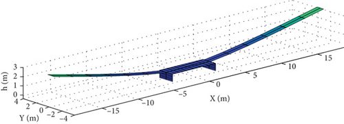
The static trimming of the combo model includes the deformation at different airspeeds and its dynamic response to determine the airspeed boundary under the instability conditions. Specifically, the pitch angle, elevator command, and throttle are trimmed for wind speed inputs of 16.7, 21.7, and 26.7 m/s with an angle of attack of 4.2 degrees. Figure 18 shows the wingtip deformation displacements of 2.1, 2.7, and 3.2 m for the three airspeed conditions, and the static deformation of the wing increases with the increase of aerodynamic forces, and the trend is in line with Figure 13(b).
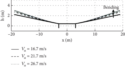
In the multirigid-body model, when the airspeed of an example UAV with a wingspan 7 m increases by 10 m/s, the dihedral angle increases by 10 degrees, leading to a wingtip deformation displacement 0.6 m. Similarly, in the combo model, when the airspeed of the full-wing configuration with a wingspan 36 m increases by 10 m/s, the wingtip deformation increases to 3.2 m, which is equivalent to a 9.5-degree increase in the dihedral angle. These results suggest that both models can effectively represent the static deformation of the flexible wing when the airspeed increases.
4.2.2. Static Deformation Analysis
Then, the deformation response is performed by gradually increasing the wind speed from 10 m/s to 30 m/s. Firstly, the coupling term is frozen and the rigid and flexible subsystems are independent, resulting in an unsteady speed 32.8 m/s. Then, considering the nonlinear coupling of motion and deformation, the coupling term is updated in real time to reduce the unsteady velocity to 26.7 m/s, and the resulting deformed shapes and displacements of the cantilever wing are shown in Figures 19 and 20.

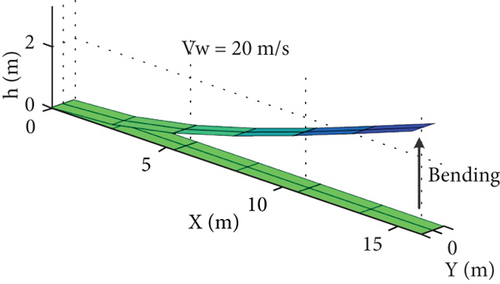
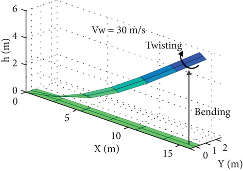

The results show that when the wind speed is lower than the unsteady airspeed, the cantilever wing in Figures 19(a) and 19(b) is bent upward with wingtip deformation displacements of 2 and 3.2 m at wind speeds of 10 and 20 m/s, and these deformations tend to be stabilized soon. Therefore, when the wind speed is lower than 20 m/s, the wing is in a small deformation state similar to Figure 18, and the deformation displacements obtained by freezing or updating the coupled terms in real time are close to those of the multirigid body model in Figure 13. However, when the wind speed is higher than the unsteady airspeed, the wing will have a combination of bending and twisting deformation, such as the 30 m/s wind speed case shown in Figure 19(c), and the deformation displacement of the wingtip in Figure 20 is oscillating and dispersed.
When the airspeed is lower than the unstable speed, the wing undergoes upper bending deformation with little amplitude, with the linear deformation response, and the multirigid-body and combo models have similar characteristics. However, as the airspeed approaches the unsteady speed, the coupling of motion and deformation causes the combined bending and twisting deformation to be no longer linear. In this case, if the coupling term freezing method is used to calculate the state matrix A of Equation (33), it varies linearly with airspeed and the motion is stable. On the contrary, if the coupling terms are updated in real time, the state matrix A does not vary linearly with airspeed increasing and the motion pattern is close to neutral or unstable. As a result, the multirigid-body model uses second-order oscillation process expressed by the dihedral angle that cannot represent the torsional deformation under the speed boundary conditions, and its accuracy is lower than that of the rigid-flexible combo model.
4.2.3. Dynamic Response Analysis
In order to analyze the nonlinear coupling between the large deformation and motion of the wing caused by the increase in airspeed, nonlinear simulations are conducted at airspeed of 17, 21, 26, and 31 m/s, with the UAV trimmed at an altitude 500 m, zero pitch angle, and angle of attack as the input, with the coupling terms updated in real time. Figure 21 shows the elevator disturbance with an input time 0.1 s, a duration 3 s, and a simulation time 20 s, and the minimum calculation step is 10−4 s.
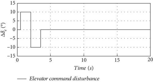
Figure 22 shows the dynamic response of the combo model for an increase in airspeed from 17 to 31 m/s. When it is below 26 m/s, the initial angle of attack increases, the initial pitch angle is zero, and the initial wingtip deformation displacement is consistent with Figure 18, and the UAV is still able to maintain a stable flight with the increase of the airspeed in this speed range. At an airspeed of 31 m/s, the initial wingtip deformation displacement in Figure 22 is 8 m, which is larger than the 3.2 m at the airspeed of 26 m/s. It can be seen that with the airspeed greater than the instability boundary, the initial wingtip deformation is more different from the case within the stability boundary.
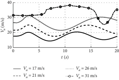
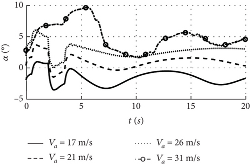
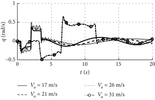
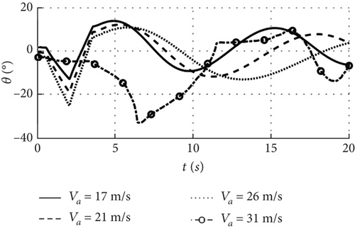
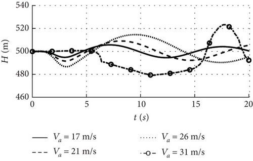

Upon inputting elevator disturbance, the UAV undergoes heaving motion, and when the airspeed remains below 26 m/s, the wing deformation causes oscillations in both airspeed and altitude that stabilize over time as shown in Figures 22(a) and 22(e), and the response pattern for each state is essentially the same. At the speed boundary 26 m/s, the wingtip deformation displacement in Figure 22(f) increases compared to the 17 and 21 m/s, and the pitch angular velocity begins oscillating first under the influence of the elevator disturbance in Figure 22(c). When the disturbance ceases, the deformation displacement tends to stabilize and the pitch angular velocity remains constant, and the response trend is comparable to that of the multirigid-body model of 10 m/s wind speed in Figure 14, indicating that the motion state at 26 m/s approaches neutral stability. However, when airspeed reaches 31 m/s, the fluctuation of wingtip deformation under elevator disturbance is more significant, and the pitch angular velocity changes drastically after the disturbance ceases, causing both the pitch angle and angle of attack to fluctuate intensely. As a result, neither airspeed nor altitude could be stabilized, indicating an unstable motion state for the UAV under these speed conditions.
The airspeed sensitivity analysis of the combo model shows that when the airspeed is close to the stability boundary, the nonlinear coupling between the wing deformation and the motion is intensified, resulting in a significant increase in the initial wingtip deformation displacement compared to that below the boundary, and the wing will also undergo bending and twisting deformation. When the airspeed exceeds the boundary, the angular velocity affected by the disturbance is the first to oscillate, and the amplitude of the wing deformation decreases when the disturbance ceases, but the oscillating motion also keeps the deformation fluctuating, which results in the global state instability. Therefore, the multirigid-body model mainly considers linear deformations, and the dynamic response shows that the state is stabilized as the deformations converge. The combo model, on the other hand, can better take into account the coupling of deformation and motion and is more suitable for cases where the wind speed or airspeed increases significantly.
5. Discussion
The rigid-body 6-DOF model shows that the full-wing configuration is more sensitive to low speed than the normal configuration in terms of phugoid and spiral modes, and the multirigid-body and combined-body models show that it is more susceptible to deformation and therefore needs to be analyzed for different airspeed intervals.
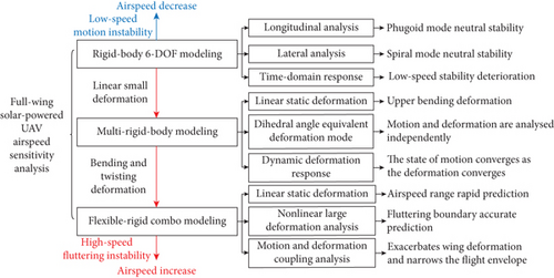
For a small-scale full-wing configuration UAV that can be considered as a rigid-body, the focus needs to be on sudden changes in stability as airspeed decreases, which is particularly significant in landing. For a medium-scale, the UAV exhibits linear deformation characteristics with increasing airspeed in the cruise speed range, which can be modeled as a multirigid-body, and the dihedral angle mode can be introduced to characterize the effect of deformation on motion. For a large-scale, the airspeed of the UAV changes dramatically under the influence of wind speed, and as the wing deformation increases in magnitude and complexity, it no longer obeys the linear characteristics, and the rigid-flexible combo model is more appropriate as it is capable of describing the coupling between the strain of the nodes and the motion. Then, the applicable airspeed range, target issues, applicability, and dynamic characteristics of the three dynamic models of the full-wing solar-powered UAV are summarized in Table 6.
| 6-DOF dynamics | Multirigid-body dynamics | Strain beam dynamics | |
|---|---|---|---|
| Airspeed range | Medium- or large-scale UAV less than 1.4 times cruise airspeed | Medium- or large-scale UAV less than 2 times cruise airspeed | Large-scale UAV greater than 2 times cruise airspeed |
| Applicable situation | Dynamical characteristics analysis | Linear structural deformation analysis | Structural deformation and fluttering speed |
| Deformation | Rigid body | Dihedral angle equivalent bending | Bending and twisting |
| Model applicability | Flight quality analysis, flight control system design, and simulation | Quantitative evaluation of linear deformation | Deformation and motion coupling analysis |
| Computation costi | Linearization time in seconds, 10 s of nonlinear simulation in seconds, real-time simulation is supported, and the iteration step is 0.01 s | The static linearization time in seconds, 10 s of nonlinear simulation time is close to 5 s, and real-time simulation is supported, and the iteration step is 0.01 s | The single state linearization time is close to 20 s, 10s of nonlinear simulation time is close to 30 minutes, real-time simulation is not supported, and the iteration step is 0.001 s |
| Accuracy | Wide range of applicable speeds, highest accuracy at cruising speed, low accuracy in low or high speed range | Consistent with the 6-DOF model at low speed, with high accuracy at cruising speed with small deformation caused by wind disturbances | The accuracy in the low-speed section is close to 6 DOF, with high accuracy at high-speed or strong wind interference conditions |
| Dynamic characteristics | Longitudinal and heading stability deteriorates as airspeed decreases | The increase of dihedral angle is detrimental to the phugoid and dihedral angle mode | Deformation and motion coupling after exceeding unstable airspeed |
- iThe performance of the computer is as follows: CPU, Intel Core i5 13th 13500H; RAM, 16 GB.
Figure 23 displays the modal characteristics and dynamic response of the full-wing solar-powered UAV under different airspeed conditions. In the cruise speed range, the stability of the UAV with 3 m wingspan decreases as airspeed decreases, and the convergence of the state response slows after wind disturbance. Especially when the airspeed is lower than 9 m/s, the longitudinal direction and heading are close to neutral stability, and the UAV is usually in the landing phase, which requires higher accuracy in airspeed and trajectory stability control. When the airspeed of the 7 m wingspan UAV is between 1.4 and 2 times the cruise airspeed, the deformation caused by the airspeed increase is small and linear, the increase in dihedral angle is less than 2 degrees, the stability of the short-period mode is improved, while the phugoid mode is close to neutral stability, and the global state is still stable with the deformation convergence. However, for a large-scale UAV with wingspan 36 m, its deformation will exhibit linear within the stability boundary and nonlinear characteristics beyond the boundary with increasing airspeed. Especially when the airspeed exceeds the unstable boundary, close to two times the cruise speed, the wing will undergo bending and twisting, leading to coupling of deformation and motion, and the overall state does not tend to stabilize as the deformation decreases.
6. Conclusions
The paper presents the airspeed sensitivity characteristics of a full-wing solar-powered UAV using three different models: a 6-DOF model, a multirigid-body model, and a strain-beam model. The differences in motion and deformation characteristics at different airspeeds are analyzed using the UAVs with wingspans of 3.5, 7, and 36 m, with the following conclusions:
The 6-DOF model is suitable for analyzing modal differences when the cruise airspeed decreases or increases slightly, while the multirigid-body model is suitable for analyzing motion modal and linear deformation response caused by airspeed increase, and the combo model is applicable to the analysis of bending and torsional deformation of the wing caused by a large increase in airspeed, as well as its nonlinear coupling to motion.
Within the cruising speed range, decreasing airspeed is unfavorable to stability, while increasing airspeed is favorable to modalities. When a small increase in airspeed induces a linear small deformation feature, the deformation can be equated with a dihedral angle and it is favorable for short-period mode. When the airspeed exceeds the unstable airspeed, the bending and twisting deformation of the wing causes pitch angular velocity oscillation and aggravates the airspeed instability.
The full-wing configuration tailless design improves the aerodynamic performance of the UAV but also exacerbates its airspeed sensitivity, mainly reflected in the near-neutral stabilization during landing deceleration and the coupling of deformation and motion caused by the airspeed increase in wind disturbance, resulting in a particularly narrow flight envelope, and only a combination of the three models can accurately obtain the UAV at the airspeed boundary.
Conflicts of Interest
The authors declare no conflicts of interest.
Funding
This work was funded by the Natural Science Basic Research Plan in Shaanxi Province of China (2024JC-YBQN-0460).
Acknowledgments
This work was funded by the Natural Science Basic Research Plan in Shaanxi Province of China (2024JC-YBQN-0460).
Open Research
Data Availability Statement
All data generated or analyzed during this study are included in this published manuscript, and all authors of this paper are responsible for the authenticity of the data.


