A Current Phase Decoupler for 5 G Smartphone Multiunit Frame Antenna
Abstract
In this paper, based on the three-dimensional frame structure between the antenna unit and the ground, a decoupling method, the current phase decoupler method, is proposed for the 5 G smartphone multiunit frame antenna. Using this method in a dual-unit antenna, the additional current path reverses the phase of the coupled current flowing through the ground to the adjacent unit, while weakening the coupled current intensity and significantly suppressing the coupling between the units. The measured results show that the coupling is less than −28 dB, and the maximum efficiency is 85.53% without adding any lossy components. In an eight-unit smartphone antenna system, the coupling of adjacent units can also be reduced below −24.6 dB with a maximum efficiency of 82.17%. This method has significant advantages over the existing decoupling methods and can be used as the preferred decoupling scheme for the future 5 G smartphone multiunit frame antenna.
1. Introduction
The fifth-generation technology in the context of wireless technology is developing rapidly, offering several significant advantages such as higher capacity, higher speed, and lower latency [1]. These advantages make 5 G widely applicable in areas such as low-power IoT, modern information agriculture, and mobile communications [2–4]. The successful application of 5 G in the field of mobile communications is inseparable from the key technology of multiple-input multiple-output (MIMO). Smartphones have been using multiunit antenna systems since 2020. Multiple units can receive and send signals together to obtain a faster transmission rate and greater transmission capacity [5, 6]. With the continuous competition of smartphone manufacturers, consumers put forward higher requirements for functional experience. The development of other components such as full screen, high-capacity battery, and ultra-definition camera makes the space of antenna design more limited. Therefore, the antenna hidden in the smartphone’s frame has become a focus in smartphone antenna design [7, 8]. However, there will be near-field and far-field coupling in the narrow frame space of tightly arranged co-frequency antenna units, which will eventually lead to a decline in the data transmission efficiency of the antenna [9]. Therefore, decoupling smartphone frame antennas has become a great challenge for antenna engineers [10–12].
In the past few years, researchers have proposed many methods to solve the coupling problem between phone antenna units, such as parasitic structures [13, 14], lossy components [15–17], and neutral microstrip [18–20], and metamaterial [21, 22]. For the decoupling of the current frame antenna, Xu and Deng proposed a pattern diversity method [12], that is, a microstrip line is used to adjust the feeding position of the monopole unit to change the radiation direction in far-field, and the port coupling can be controlled below −14 dB. In addition, lossy components are proposed to reduce coupling [23]. By adding inductance and capacitance between tightly arranged units, the coupled current between units is suppressed, and the port coupling is less than −11.6 dB, but the average efficiency is only 40%. A shared radiator antenna structure has been a common novel decoupling method in recent years. The bandwidth of a rectangular frame antenna using this structure can cover 3.3–4.2 GHz [24], the coupling is less than −10.5 dB, and the average efficiency can reach 74.1%. Compared with the decoupling of lossy components, the antenna efficiency has been greatly improved, but the decoupling effect within the bandwidth is low. Then, a phone antenna is designed on the inner and outer sides of the frame substrate by using the Differential Mode/Common Mode (DM/CM) feeding mode theory [25], with coupling less than −24.1 dB. The antenna considers the spatial characteristics of the three-dimensional (3-D) and multilayer frame structure and realizes very low coupling. However, the antenna needs additional capacitance for matching adjustment, resulting in the maximum efficiency of the unit in CM feeding mode being only 69%. Additionally, spatial diversity technique can enable antenna arrays to achieve isolation levels below −20 and −17.5 dB, respectively, with antenna efficiencies not less than 70% [26, 27]. However, the physical size of these antennas is relatively large and occupies a substantial area on the main board, which is unfavorable for the integration of other mobile phone components. Although there are various decoupling methods for frame antennas, the novel decoupling method of smartphone multiunit frame antenna with a simple structure, high decoupling efficiency, and high radiation efficiency is still the aim of antenna engineers.
Generally, in a planar antenna structure, the position of the two units is determined, and the length of the coupled current with the ground as the path will also be determined. However, the antenna with a 3-D frame structure has more design space to change the coupled current length. Therefore, a novel phase microstrip decoupling structure is proposed in this paper, and an inverted-F frame antenna system verifies its feasibility. One end of the microstrip is connected to the inverted-F antenna unit, and the other is connected to the ground. The path of about one resonant wavelength composed of ground and the phase decouplers will change the phase and weaken the intensity of the coupled current. When applied to the eight-unit antenna system, the experimental results are in good agreement with the simulation results, proving the method’s effectiveness.
2. The Decoupling Principle of Phase Decoupler
In the smartphone antenna, two adjacent units absorb each other’s electromagnetic energy, and the received electromagnetic energy interferes with the antenna’s radiation in the form of a coupled current [28]. Restraining the coupled current, the coupling problem of the antenna system can be effectively solved. The coupling action between the two units is shown in Figure 1(a). On the left, Unit 1 and Unit 2 are two adjacent units in the antenna system. The ground is on the bottom of the units, λ is the equivalent electrical length corresponding to the electromagnetic wave radiated by the unit, d0 is the distance between the two units, and d is the equivalent transmission path length of the coupled current. Normally (seen in Figure 1(a)), d and d0 are correlated; when d0 increases, the equivalent transmission path length d increases accordingly. Figure 1(b) shows a simplified schematic diagram of the coupled current change as d changes. Where f0 is the resonant frequency of the unit and c is the speed of light in the vacuum. When the unit distance d0 is small, in which the equivalent transmission path length d is less than λ/2. Ideally, the phase of the coupled current at the end of Unit 2 is opposite to that at the end of Unit 1. Because the amplitude of the coupled current is large, there will be strong coupling between the units. However, when the unit distance d0 is large, in which the equivalent transmission path length d is greater than λ/2 but less than λ. The phases of the coupled current at the end of the two units are the same, and the amplitude of the coupled current decreases so that the coupling can be alleviated to some extent. In particular, when selecting an appropriate unit distance d0 so that the equivalent transmission path length d is exactly equal to λ, the coupled current flowing to Unit 2 can reach a minimum amplitude within a wavelength. At this point, the coupling of the two units will be minimized.
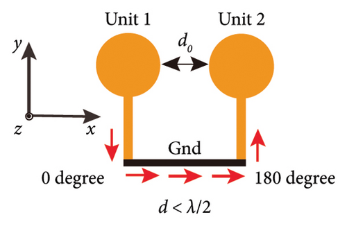
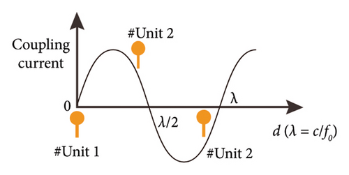
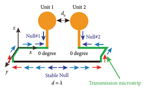
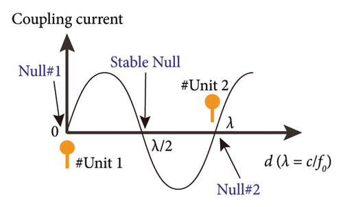
Usually, getting a length of λ equivalent transmission path needs to be achieved by increasing the unit distance d0. However, this is not the best choice for the 5 G smartphone with a long wavelength and limited design space. Suppose there is a way to re-plan the coupled current path so that the unit distance d0 is no longer related to the equivalent transmission path length d of the coupled current. In that case, it will be possible to propose efficient decoupling while keeping the distance d0 constant. For example, in Figure 1(c), by adding a transmission path between units and the ground (the green microstrip line), Null 1, Null 2, and Stable Null will appear at the end of Unit 1, Unit 2, and the λ/2 coupled path, respectively. The coupled current transmission path can be artificially extended to equal λ. Because of symmetry, the coupled current phase at the end of Unit one is the same as at the end of Unit 2. At this point, the coupled current amplitude can be decreased. Thus, the coupling between the two units will be minimized. That provides a new method to reduce the coupling without changing the unit distance d0. The additional transmission paths introduced will later be called phase decouplers. The purpose of efficient decoupling would be achieved by introducing the phase decouplers.
3. Decoupling of 5 G Dual-Unit Frame Antenna System
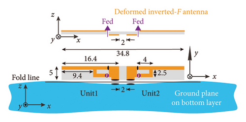
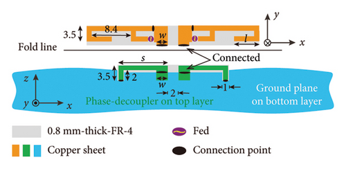
To verify the decoupling effect of the phase decoupler, the classical dual-unit inverted-F antenna is selected as the base uncoupling unit, and the decoupling is realized by introducing the phase decoupler. The antenna pair model obtained is shown in Figure 2(a). The uncoupled Unit 1 and Unit 2 are perpendicular to the substrate and connected to the ground at the bottom layer of the substrate. The nearest distance between the units is 2 mm (much less than the 1/2 wavelength corresponding to the resonance frequency). According to the decoupling principle above, two phase-decouplers are introduced at the connection between the units and the ground in Figure 2(a), and a new unit pair with decoupling ability is obtained, as shown in Figure 2(b). The green U-shaped microstrips with length s in Figure 2(b) are the phase decouplers. The unit is connected at one end of the phase decoupler, and the ground is connected at the other end of the decoupler through a hole structure. It is worth noting that the phase decoupler introduced is designed on the top layer of the substrate and takes up the extra substrate. By controlling the length s of the phase decoupler, the coupled current of the unit to the ground can be changed. Considering that the introduction of the phase decoupler will change the electrical length of the unit in Figure 1(a), a branch with a length of l is added at the end of the inverted-F unit in Figure 2(b), and the resonance can be adjusted at the stable frequency by changing parameters l.
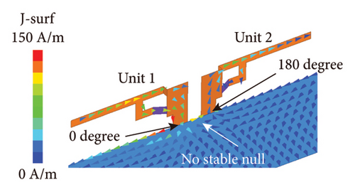
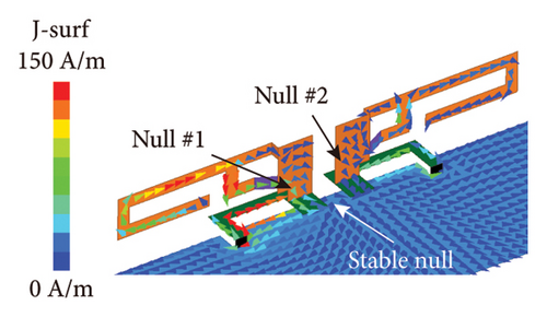
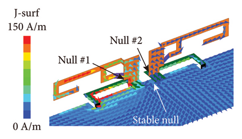
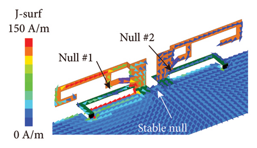
The decoupling capability of phase decoupler is demonstrated through the surface current and S-parameters of dual-unit inverted-F antennas. Simultaneously, comparing the surface current and S-parameters under different antenna size parameters helps determine the optimal structural dimensions of the antenna. The surface current distribution before and after decoupling is simulated and analyzed when Unit 1 is excited at 3.5 GHz, and the results are shown in Figure 3. Before decoupling (see Figure 3(a)), the coupled current phase at the end of Unit 2 is 0°, while at the end of Unit 1 is 180°. There is a strong current distribution on the surface of Unit 2. When introducing the phase decoupler, to ensure that the resonance frequency is stable at 3.5 GHz, both the decoupler’s length s and the unit branch’s length l must be adjusted simultaneously. Figures 3(b), 3(c), and 3(d) show the surface current distributions after introducing the phase decouplers. It can be seen that the phase decouplers can significantly reduce the surface current distribution of Unit 2. As analyzed in Figure 1, three nulls appear (Null 1, Null 2, and Stable Null). When the phase decoupler length s is 8, 10, and 12 mm (the length of the unit branch changes correspondingly to 7, 4, and 3 mm to ensure the resonance frequency is 3.5 GHz), Stable Null appears near the center of the coupled transmission path, while Null 1, and Null 2 move toward the center of the coupled current transmission path with the increase of the length of the phase decouplers. When s = 8 mm, Null 1, and Null two exist at the bottom of the units, which indicates that the coupled current transmission path length d is less than the wavelength λ at this time. When s = 10 mm, Null 1, and Null 2 exist at the connection between the phase decouplers and units, where d approximately equals wavelength λ. When s = 12 mm, Null 1, and Null 2 exist at the phase decouplers, where d is greater than the wavelength λ. Obviously, from the comparison of Figures 3(b), 3(c), and 3(d), it can be seen that the decoupling effect is better when s = 10 mm and l = 4 mm.
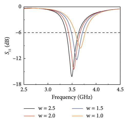
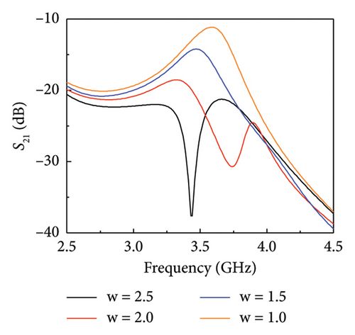
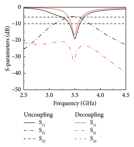
Next, simulations were conducted on the variation of S-parameters of antenna pairs with changes in s and l, aiming to analyze the decoupling effectiveness of the phase decoupler more accurately, and the results are shown in Figure 4(a). When s = 8 mm, the S21 is less than −10.0 dB in −6 dB bandwidth, which can realize effective decoupling. When s = 10 mm, the coupling will be greatly reduced, and the S21 is less than −25.85 dB. When s = 12 mm, the coupling will gradually increase. The results of S parameters are consistent with the analysis of surface current distribution. After conducting more detailed simulations on the length s of the phase decoupler and the length l of the bent branch of the inverted-F antenna, a set of optimum parameters is obtained: s = 10.5 mm, l = 4 mm. Additionally, the width w at which the antenna unit interfaces with the decoupler affects the impedance when the coupling current flows into or out of the unit, significantly impacting the antenna’s S-parameters. Simulation results of the antenna’s S-parameters varying with w are shown in Figures 4(b) and 4(c), where w values are 2.5, 2, 1.5, and 1 mm. From Figure 4(b), it is observed that as w decreases, the antenna’s resonance shifts to higher frequencies with a shallower resonance depth. Figure 4(c) indicates that smaller w values lead to stronger coupling of the unit. Ultimately, the optimal parameter for w was determined to be 2.1 mm, and the space occupied by the phase decouplers is 23 × 3.5 mm. The simulated S parameters of the pair before and after decoupling are shown in Figure 4(d). It is clear that the optimized phase decouplers introduced achieve efficient decoupling.

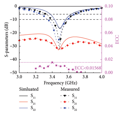
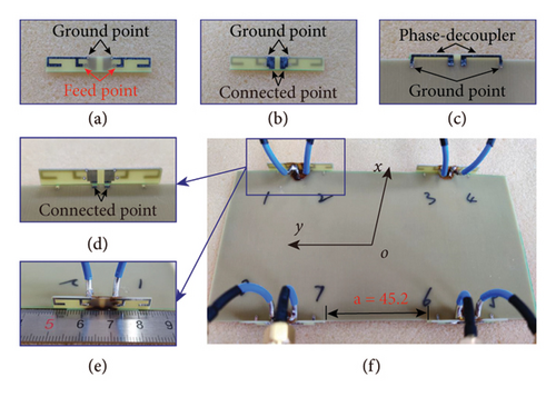
The dual-unit pair is fabricated and measured according to the antenna model and size parameters with the phase decouplers in Figure 2(b). Each unit is fed with a semiflexible coaxial line. The feed line is welded through holes on the inverted-F branch at the top layer of the unit substrate, and the ground line is welded on.
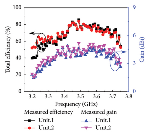
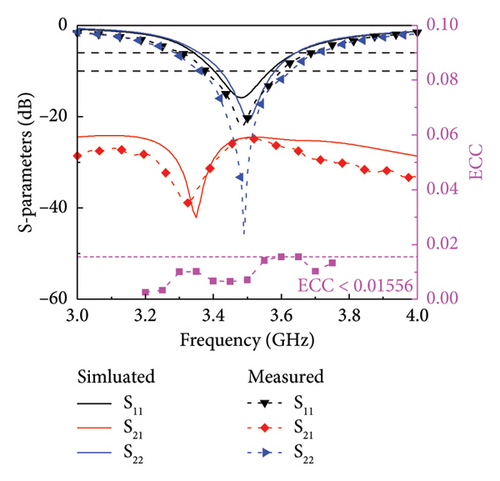
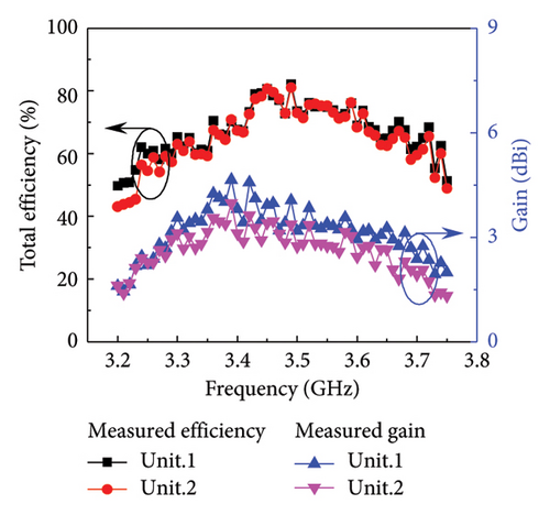
The ground at the bottom layer of the unit substrate. The S parameters results and the far-field ECC is obtained according to the calculation method in reference [24] are shown in Figure 5(a). The simulated −6 dB bandwidth of Unit 1 and Unit 2 is 3.37–3.63 GHz. The measured bandwidth of Unit 1 is 3.32–3.66 GHz. The measured bandwidth of Unit 2 is 3.27–3.67 GHz. Compared with the simulated bandwidth, the measured bandwidth increases by about 80 MHz. At 3.4–3.6 GHz, the measured coupling is less than −28 dB, which is better than the simulated result. Considering that the actual welding will affect the unit’s impedance, the measured results differ slightly from the simulated results. In the bandwidth range, the far-field ECC of Unit 1 and Unit 2 is lower than 0.016. The efficiency, gain and far-field radiation gain parameters are measured in the microwave anechoic chamber, as shown in Figure 5(b). The maximum efficiency and gain of Unit 1 are 85.53% and 4.88 dBi, respectively, and the maximum efficiency and gain of Unit 2 are 83.92% and 5.13 dBi at the resonant frequency.
4. Design of 5 G Eight-Unit Frame Antenna System
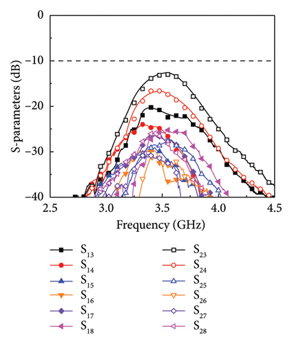
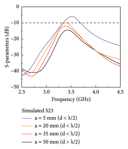
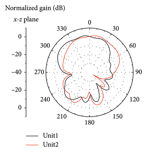
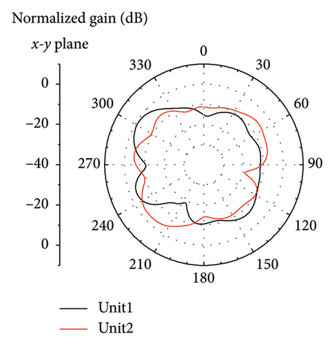
In the eight-unit antenna system, each antenna pair using the phase decouplers is symmetrically placed on the long side of the ground. The nearest distance between the pairs is a = 45.2 mm, as shown in Figure 6. Also, due to the influence of ground edge current, the matching needs to be adjusted slightly, that is, the parameters of the unit and decoupler need to be adjusted again. Here, l = 3.3 mm, w = 1.6 mm, s = 12 mm, and other parameters are the same as those in Figure 2(b). The measured S parameter, calculated ECC, efficiency, and gain are shown in Figures 7(a), 7(b), and 7(c). The measured −6 dB bandwidth of Unit 1 is 3.30–3.69 GHz, the maximum efficiency and gain can reach 82.17% and 3.63 dBi, respectively, and the minimum efficiency and gain are 60.1% and 2.44 dBi in the bandwidth range of 3.4–3.6 GHz. The measured bandwidth of Unit 2 is 3.28–3.70 GHz, the maximum efficiency and gain can reach 81.07% and 4.58 dBi, and the minimum efficiency and gain are 59.6% and 2.94 dBi, respectively. The measured coupling results between each unit in the bandwidth range are all less than −12.82 dB (coupling between Unit 2 and Unit 3), where the coupling between Unit 1 and Unit 2 is less than −24.6 dB and the ECC is less than 0.016. Figure 7(d) shows the simulated S23 with different pair distances a. The results show that when no other decoupling methods are used, the S23 can be reduced by increasing the pair’s distance a. In the actual design, when a is 20–50 mm, a low coupling of −10 to −15 dB can be obtained. In fact, if want to keep the pair’s distance a small, you can also use other decoupling methods between Unit 2 and Unit 3 to reduce the S23 further. The measured results of the far-field 2D radiation patterns of the units are shown in Figure 8. The pairs can achieve a maximum gain of 4.5 dB in the far-field, and each unit will produce radiation on both sides of the y-axis, so there will be no radiation loss.
The comparison results between the decoupling method proposed in this paper and the decoupling method in the existing 5 G smartphone antenna are given in Table 1. It can be seen that the efficient isolation–24.6 dB can be obtained by introducing the phase decoupler, and this isolation is superior to that of all comparative references. In addition, it is worth pointing out that the phase decoupler is located directly below the antenna unit, which fully uses the spatial characteristics of the 3-D frame structure. It will not occupy too much space, and the design is simple. Therefore, it has great competitiveness in the decoupling of the antenna in the future.
| Reference | Size (λ3) | Methods | BW (−6 dB) | Iso. (dB) | Eff. (%) |
|---|---|---|---|---|---|
| [12] | 0.12 × 0.29 × 0.009 | Pattern diversity | 7.4% (3.36–3.62 GHz) | 14.6 | > 40 |
| [17] | 0.67 × 0.12 × 0.009 | Multifeed | 13.4% (3.3–3.77 GHz) | 16.4 | > 62 |
| [23] | 0.23 × 0.035 × 0.009 | Lumped-components | 4.1% (3.6–3.75 GHz) | 11.5 | > 23 |
| [25] | 0.33 × 0.058 × 0.019 | D/C mode | 7.7% (3.27–3.53 GHz) | 24.1 | > 61.6 |
| [26] | 0.38 × 0.41 × 0.01 | Space diversity | 95.5% (2.3–6.5 GHz) | 20 | > 70 |
| [27] | 0.25 × 0.15 × 0.003 | Space diversity | 84.7% (2.37–5.85 GHz) | 17.5 | > 85 |
| [29] | 0.23 × 0.072 × 0.009 | Parasitic-grounding | 10.5% (3.34–3.71 GHz) | 17 | > 57.9 |
| [30] | 0.49 × 0.374 × 0.019 | Parasitic-branch | 23.4% (3.18–4 GHz) | 14 | > 68 |
| [31] | 0.26 × 0.06 × 0.06 | Meta-material | 20% (4.36–5 GHz) | 10 | > 46.8 |
| This work | 0.41 × 0.08 × 0.009 | Phase-decoupler | 11.1% (3.3–3.69 GHz) | 24.6 | > 60 |
5. Conclusions
This paper proposes an efficient multiunit antenna decoupling method, the phase decoupler method, which can change the coupled current. By introducing the phase decoupler only occupying a small clearance, the designed antenna system can reduce the coupling from −5.8 to −24.6 dB at a unit distance of 2 mm. The experimental measurement results have significant advantages over the measured results of similar sub-6 GHz antennas. Of course, the antennas demonstrated in this paper exhibit a narrow bandwidth, and an eight-element MIMO system may not meet the high data rate requirements of future 5 G communications. However, the decoupling method proposed here shows good generality. The decoupling principle and the approach of introducing phase decoupler hold significant reference value for decoupling multielement frame antennas in future smartphones.
Conflicts of Interest
The authors declare no conflicts of interest.
Funding
This work was supported by the National Key R&D Program of China (Grant No. 2023YFF0616800), the Natural Science Foundation of Zhejiang Province under Grant nos. LZ23A020002. The authors would like to express their sincere appreciation to these supports.
Acknowledgments
This work was supported by the National Key R&D Program of China (Grant no. 2023YFF0616800) and Natural Science Foundation of Zhejiang Province under Grant no. LZ23A020002. The authors would like to express their sincere appreciation to these supports.
Open Research
Data Availability Statement
The data that support the findings of this study are available from the corresponding author upon reasonable request.


