Optimum Coordination of Multi-Band Power System Stabilizers and STATCOM Using the Modified Particle Swarm Algorithm
Abstract
In this paper, to improve the small signal stability of the power system, the optimal coordination of multi-band power system stabilizers (MB-PSSs) and static synchronous compensator (STATCOM) has been done. The study is conducted on a standard four machines and two areas power system. To create coordination, a modified version of the particle swarm algorithm as well as the integral time absolute error (ITAE) criterion are proposed. To evaluate the proposed stability method in different operating conditions and in the form of two scenarios, a three-phase fault with a duration of 200 ms has been applied in the communication line between the two areas. After the simulation, the values of overshoot, undershoot, settling time, and ITAE criteria for the proposed stability method have been calculated and their values have been compared with the results of power system stabilizer (PSS) and MB-PSS stabilization methods. The results indicate that the proposed combined method of MB-PSS and STATCOM performed better than the other two methods in improving the dynamic stability of the power system and has the lowest value of the criteria. The values of ITAE for the PSS, MB-PSS stabilization methods and the proposed MB-PSS and STATCOM combined method in the first scenario are equal to 0.002354, 0.0.001496, and 0.001242 p.u. and in the second scenario it is equal to 0.0.007418, 0.004015, and 0.003435 p.u., respectively.
1. Introduction
Improving dynamic stability has emerged as a paramount concern within the realm of power system research. With the progress and expansion of power systems and transmission lines in recent years, the significance of stability has witnessed a substantial rise [1, 2]. Consequently, the implementation of a power system stabilizer (PSS) has become crucial to enhance dynamic stability. The PSS operates by applying an appropriate control signal to dampen power system oscillations. It is worth noting, however, that the effectiveness of a PSS relies on its suitability and accurate design. The utilization of an unsuitable or improperly designed PSS may not only fail to enhance stability but can also trigger instability [3]. Due to the interconnected nature of large-scale power systems, particular attention has been given to the damping of low frequency oscillations ranging from 0.2 to 3.0 Hz. If left unchecked, these oscillations can undermine the efficiency of network transmission lines and, in extreme cases, lead to power system desynchronization or even collapse. To address this, generators are equipped with lead-lag power system stabilizers (PSSs) that generate complementary signals to enhance excitation system stability. By increasing the damping of low frequency oscillations, PSS stabilizers contribute in improving the stability limits and transmission capacity within the power system [4]. However, it should be noted that PSS stabilizers are designed for specific operating conditions and may not perform optimally in all load scenarios. To overcome this limitation, a new generation of stabilizers, namely the multiple-band power system stabilizers (MB-PSSs), has been introduced [3]. The MB-PSS stabilizer exhibits enhanced performance across a broader range of power fluctuations and effectively dampens low frequency oscillations. In the literature, numerous research articles have explored various PSSs and employed diverse design methods. In this context, a brief review of some of these approaches is presented below.
In [5], a social network search algorithm (SNSA) is proposed for optimizing PSS parameters to enhance power system stability. The SNSA effectively explores the solution space, providing optimal settings for PSS parameters. Simulation results indicate improved damping of power system oscillations. Latif et al. [6] introduces a firefly algorithm (FA)-based approach for PSS parameter optimization. The FA is employed to search for optimal settings, aiming to improve the stability of the power system. Simulation results demonstrate the efficacy of the FA-based method in enhancing power system stability. The study outlined in [7] focuses on a bat algorithm (BA) applied to optimize PSS parameters. The BA efficiently explores the solution space to find optimal settings for enhancing power system stability. Simulation results show improved damping characteristics for low frequency oscillations. In [8], an imperialist competitive algorithm (ICA) is utilized for optimizing PSS parameters. The ICA is employed to efficiently search for optimal settings, contributing to enhanced power system stability. Simulation results demonstrate the effectiveness of the ICA-based approach in damping power system oscillations. The research presented in [9] proposes a cat swarm optimization (CSO) algorithm for optimizing PSS parameters. The CSO efficiently explores the design space to find optimal settings for improving power system stability. Simulation results highlight the capability of the CSO-based method in achieving effective damping of oscillations.
In [10], the authors propose a novel approach for PSS design based on a hybrid algorithm combining gray wolf optimization (GWO) and sine cosine algorithm (SCA). The hybrid algorithm optimizes PSS parameters to achieve improved damping of power system oscillations. Simulation results demonstrate the effectiveness of the proposed approach. The study presented in [11] introduces a fuzzy logic-based PSS design. By incorporating fuzzy logic control techniques, the PSS can adaptively adjust its parameters based on system operating conditions and disturbances. The fuzzy logic-based PSS shows promising results in enhancing power system stability. In [12], the authors focus on the application of artificial neural networks (ANNs) for PSS design. ANNs are trained using historical system data to model the complex relationship between system variables and PSS parameters. The trained ANN-based PSS exhibits improved damping performance and adaptability to varying system conditions. The paper described in [13] proposes a robust PSS design technique using H∞ control theory. By formulating the PSS design as an H∞ control problem, the approach ensures robust stability and performance in the presence of uncertainties and disturbances. Simulation results demonstrate the robustness of the proposed design method. In [14], the authors investigate the integration of wide area measurement systems (WAMSs) with PSS for enhanced stability control. By utilizing real-time measurements from multiple locations in the power system, the WAMS-PSS system provides superior damping of oscillations and improved stability. Experimental results validate the effectiveness of the WAMS-PSS integration.
With the introduction of flexible AC transmission system (FACTS) devices and their integration into transmission lines, the regulation of electricity flow in these lines has been achieved. The implementation of these flexible controllers enhances system utilization, offering power system operators more alternatives. Among the second-generation FACTS devices, a static synchronous compensator (STATCOM) significantly influences the voltage and dynamic stability of the power system [15]. By precisely managing power flow in transmission lines, STATCOM mitigates subsynchronous resonance, dampens inter-area power fluctuations, and enhances transient stability [16]. The interaction between stabilizers may impact the damping of specific modes of rotor oscillations, particularly in situations where a critical error has been rectified in the power system utilizing FACTS devices. The interaction among damper controllers can adversely affect generator rotor damping, leading to instability in weakly connected systems and thereby, restricting the power system’s operational range. Numerous researchers have focused on enhancing system performance through the coordination of stabilizers and FACTS devices [11, 17, 18]. The methods reviewed are often based on intricate nonlinear simulations or linearized power system models. Linear methods struggle to accurately model the complex dynamics of power systems, especially during critical errors, resulting in high errors in designs based on such methods [19]. To address this issue, evolutionary algorithms have been employed.
Due to performance limitations, PSS stabilizers alone may not be able to stabilize the power system under all operating conditions. However, the use of multi-band stabilizers (MB-PSS) can address the weaknesses of traditional PSS stabilizers. Additionally, a review of the literature indicates that utilizing the STATCOM compensator is considered the most suitable approach for improving rotor angle stability. However, currently, a matter of great importance is the establishment of coordination between PSSs and STATCOM compensators. To achieve harmonious operation, it is essential to define appropriate objective functions and utilize optimization algorithms for coordination purposes.
In this study, an enhanced particle swarm optimization (PSO) algorithm was employed to design controllers for both the MB-PSS and the STATCOM power system stabilizers, aiming to achieve the desired coordination. By minimizing the cost function, this algorithm determines optimal controller parameters to efficiently dampen inter- and intra-regional fluctuations in the shortest possible time and with minimal amplitude. The effectiveness of the designed controller was evaluated in a standard four-machine power system under various performance states through MATLAB simulations.
The remainder of this paper is structured as follows:
The second section describes the power system model. Also explained in this section are the MB-PSS and STATCOM stabilizer models. In the third section, we will then examine the MPSO algorithm. The results are presented in the fourth section, and the paper concludes with the presentation of the results in the fifth section.
2. Multi-Machine Power System Model
In this paper, a standard four-machine power system is selected for simulations. The understudy power system consists of two interconnected areas linked by extensive transmission lines. Therefore, it is feasible to accurately simulate the impact of compensation techniques on mitigating inter-area mode oscillations. Figure 1 depicts the model of the power system with four machines in two areas that are used to conduct dynamic stability studies. Two 230 kV transmission lines connect two generation units with a combined capacity of 1,800 MW in each area [20]. The generators in the first area have H = 6.5s, and the generators in the second area have H = 6.175; all other generator parameters are the same. Loads are modeled as constant impedance. Generator G1 is designated as the slack bus.

2.1. PSS Model
The stabilizer of the power system is the electronic feedback control of the generator excitation system, which compensates for the phase difference between the excitation input and the electric torque by creating the proper torque in the generator rotor and dampening oscillations in the shortest time possible. Numerous PSSs have been designed and implemented, with the lead-lag stabilizer (PSS) being the most significant. Figure 2 depicts the model of this stabilizer.

The PSS stabilizer has an acceptable performance at the predetermined working point; however, as a result of the change in the power system, it no longer possesses its former capability and may cause system instability. Another type of PSSs is the multifrequency stabilizer, also known as the multiband PSS, which can perform well under a variety of power system conditions. In this stabilizer, three intervals of the low, medium, and high frequency are considered, and two stages of lead-lag compensator are used for each interval. Figure 3 depicts a comprehensive block diagram of this stabilizer’s components [21].
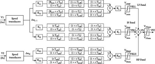

At the entrance of this stabilizer, a speed converter is utilized. Figure 4(a) depicts the speed converter for low and middle frequencies, while Figure 4(b) depicts the speed converter for high frequencies. The speed converters parameters are given in the appendix.


2.2. Static Synchronous Compensator (STATCOM)
A STATCOM that functions as a parallel reactive power compensator, whose capacitive or inductive output current can be independently controlled from the system’s AC voltage. Since STATCOM is placed in parallel with transmission lines, it dynamically adjusts the required reactive power within the converter’s power limit. The converter absorbs a current from AC line, and the reactive component of this current is consumed automatically to balance the required active power of the capacitors on DC circuit and the current active component within permitted range [22]. As depicted in Figure 5, the fundamental electronic block of a STATCOM is a voltage source converter (VSC), which converts a DC input voltage to a three-phase output voltage at the main frequency, with controllable amplitude and phase angle. The controller also includes a DC capacitor and coupling transformer.
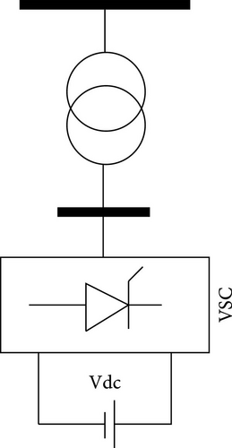
The principle of STATCOM operation is based on the fact that a voltage source converter generates a controllable AC voltage equips the leakage inductance of the transformer, causing an exchange of reactive and active power between the transmission system and the STATCOM. This ensured that the VSC’s output AC voltage is just sufficient to distribute the required reactive current. As the voltage source for the converter, the DC capacitor voltage is adjusted to the necessary size for any voltage of AC bus automatically. Therefore, the STATCOM capability is utilized not only to regulate the voltage but also to improve the system’s damping. The STATCOM parameters are provided in Table 1.
|
3. Objective Functions
In Equation (3), the weight coefficients ω1 and ω2 are used to combine and balance the ITAE and FD functions. These coefficients play a role in harmonizing the two functions within the objective function.
4. Modified Particle Swarm Optimization (MPSO) Algorithm
Eberhart and Kennedy first described the particle swarm algorithm in 1995. This technique was inspired by the schooling behavior of fish and the migration of birds. This method was used to uncover the patterns that regulate the simultaneous flight of birds and their abrupt path changes. In this algorithm, particles are positioned in the problem’s search space, and each particle measures the objective function based on its current position. Applying random adjustments, each particle then chooses its travel rate depending on the history of its current location and the best location it has encountered or the experiences of one or more other particles in the group. After shifting all of the particles (using the preceding approach), the following repetition occurs. Eventually, the entire population, like a flock of birds searching for food, will reach the objective function’s ideal position. Because the particles in this algorithm move around the search space by following the best particles, their speed is increased. This algorithm has a higher convergence rate than other evolutionary algorithms.
The initial weight w is responsible for the dynamic modification of the particle velocity, creating a balance between local and global searches and minimizing the number of iterations required to get the optimum solution. Equation (6) yields the initial weight used in Equation (4), where iter_max represents the maximum number of iterations and iteration illustrates the iterations number. The relationship demonstrates how to update the initial weight coefficients, where wmin and wmax are the minimum and maximum weights, respectively.
By changing the PSO method to examine three types of optimal locations in multigroup space, it is possible to boost the convergence rate and prevent premature convergence. In addition, despite the dependence on gbest, a group with a large number of components is transformed into a number of smaller groups with a lesser number of components, and the search in each group is conducted independently. Consequently, the search space will be searched further, and the likelihood of locating superior answers will grow.
5. Simulation Results
The performance of the power system has been evaluated in three modes: (1) with a PSS stabilizer, (2) with a MB-PSS stabilizer, and (3) with a MB-PSS stabilizer and STATCOM, as well as under two operating situations. Table 2 displays the reactive and active power unit values for each unit.
| Scenarios | P1 | Q1 | P2 | Q2 | P3 | Q3 | P4 | Q4 |
|---|---|---|---|---|---|---|---|---|
| First scenario | 0.7778 | 0.1021 | 0.7777 | 0.1308 | 0.7989 | 0.0914 | 0.7778 | 0.0918 |
| Second scenario | 0.6667 | 0.0992 | 0.9624 | 0.2083 | 0.7778 | 0.0960 | 0.6667 | 0.1036 |
The coordination constraints are accumulated in Table 3. In order to validate the accuracy of the proposed MPSO algorithm, PSO, genetic algorithm (GA), and also GWO were employed for optimal coordination.
| Change limits of the MB-PSS | Changes limits of the STATCOM controller | ||
|---|---|---|---|
| KL1A, KL1B, KL1C, KL1D | [1 5] | Kp (Vdc regulator) | [0.001 0.1] |
| KL2A, KL2B, KL2C, KL2D | [0.1 3] | Ki (Vdc regulator) | [0.001 0.1] |
| KLA, KLB, KLC, KLD | [0.1 3] | Kp (current regulator) | [0.01 1] |
| KI1A, KI1B, KI1C, KI1D | [0.1 5] | Ki (current regulator) | [1 10] |
| KI2A, KI2B, KI2C, KI2D | [0.1 3] | Kf (current regulator) | [0.01 1] |
| KIA, KIB, KIC, KID | [0.1 3] | — | — |
| KH1A, KH1B, KH1C, KH1D | [0.1 5] | — | — |
| KH2A, KH2B, KH2C, KH2D | [0.1 3] | — | — |
| KHA, KHB, KHC, KHD | [0.1 3] | — | — |
The convergence curve of optimization algorithms was obtained after optimal design of stabilizers and coordination with STATCOM as shown in Figure 6.
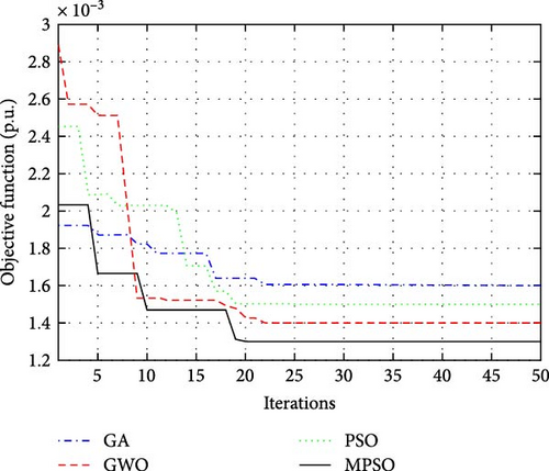
As shown in Figure 6, the proposed MPSO algorithm has converged to a lower value than all other algorithms. The final value of the objective function for the MPSO algorithm is equal to 0.00132 p.u., while the value of the objective function for the PSO, GA, and GWO algorithms was 0.00152, 0.00161, and 0.0043, respectively. Table 4 provides the optimal parameters of the MB-PSS and STATCOM selected through proposed MPSO.
| Gen | KL1 | KL2 | KL | KI1 | KI2 | KI | KH1 | KH2 | KH |
|---|---|---|---|---|---|---|---|---|---|
| G1 | 1.236885 | 0.110709 | 1.191244 | 2.128714 | 0.099322 | 0.850845 | 3.556078 | 0.835406 | 1.251601 |
| G2 | 2.439377 | 1.209874 | 0.860866 | 1.373446 | 3.114877 | 0.360379 | 2.158693 | 2.668548 | 4.492019 |
| G3 | 3.873806 | 1.41991 | 0.931612 | 2.117191 | 1.097119 | 1.845167 | 1.195117 | 1.882277 | 4.957338 |
| G4 | 1.773313 | 2.599814 | 1.003531 | 1.136572 | 0.961857 | 1.322552 | 1.075944 | 1.078369 | 3.235584 |
| STATCOM | Ki (Vdc Reg) | Kp (current Reg) | Ki (current Reg) | Kf (current Reg) | Kp (Vdc Reg) | ||||
| 0.0513 | 0.0304 | 0.36 | 8.24 | 0.47 | |||||
Table 5 presents the optimized parameters of the PSS stabilizer obtained through the hybrid butterfly optimization algorithm–PSO algorithm [24]. On the other hand, Table 6 displays the parameters of the MB-PSS stabilizer employed.
| Gen | K | T1 | T2 | T3 | T4 |
|---|---|---|---|---|---|
| G1 | 21.54544 | 0.341689 | 0.304845 | 0.732812 | 0.415684 |
| G2 | 33.32024 | 0.205052 | 0.86286 | 0.419354 | 0.713609 |
| G3 | 24.29973 | 0.272612 | 0.187378 | 0.539682 | 0.569025 |
| G4 | 25.54075 | 1.05789 | 0.641436 | 0.463679 | 1.041235 |
| Gen | KL1 | KL2 | KL | KI1 | KI2 | KI | KH1 | KH2 | KH |
|---|---|---|---|---|---|---|---|---|---|
| G1 | 1.343197 | 0.108211 | 1.019333 | 2.165361 | 0.107055 | 0.956606 | 4.172971 | 0.854444 | 1.340428 |
| G2 | 2.884205 | 1.250911 | 0.981165 | 1.498524 | 3.400882 | 0.428775 | 2.252323 | 2.733214 | 4.249391 |
| G3 | 4.456381 | 1.352231 | 0.817817 | 2.102986 | 1.181747 | 1.642195 | 1.381842 | 2.08414 | 4.070417 |
| G4 | 1.837251 | 2.507631 | 1.105666 | 1.313982 | 1.085127 | 1.537925 | 0.917 | 1.123809 | 3.137392 |
We have examined the performance of each of the proposed control systems by introducing a 200 ms communication delay between the two areas. The most destructive type of fault in power systems is three-phase to ground fault, and if the power system can maintain its stability in the condition of three-phase to ground fault, it is likely that it can remain stable in other faults as well.
However, it is crucial to note that power system stability studies typically set a maximum duration of 200 ms for three-phase faults. If the fault persists beyond this time, maintaining stability in the power system becomes virtually impossible. First, the output active and reactive power of the generators has been established following the first row of Table 1 (First scenario). Figure 7 demonstrates the variations in generator angular speed.
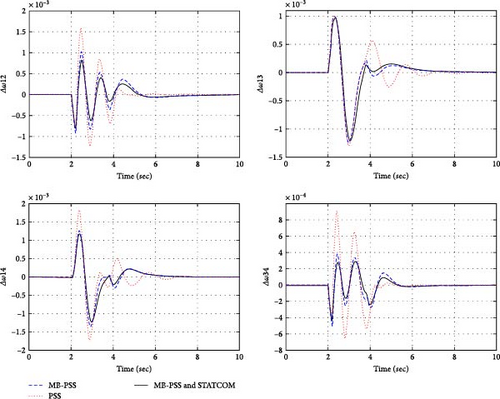
Table 7 displays the maximum overshoot, settling time, and ITAE criterion values for each stabilizer. Notably, the amount of settling time has been estimated with a 4% variation of the final value, as well as the amount of maximum overshoot and undershoot among all curves (intra- and inter-area fluctuations). The red and blue dotted lines in Figure 6 represent the power system with PSS and MB-PSS stabilizers, respectively. In addition, a black line depicts the variations in angular speed caused by the simultaneous presence of MB-PSS and STATCOM.
| First scenario | ITAE | % OV | % US | TS | FD |
|---|---|---|---|---|---|
| PSS | 0.002354 | 2.244722 | −1.96206 | 5.31262 | 16.4584 |
| MB-PSS | 0.001496 | 1.218883 | −1.22756 | 3.893067 | 14.8792 |
| MB-PSS and STATCOM | 0.001242 | 1.005807 | −1.0582 | 3.244177 | 13.4589 |
By altering the reactive and active power of generators, the control systems performance, under novel situations was evaluated. An appropriate stabilizer should be able to attenuate fluctuations in the quickest period possible and with the smallest amplitude possible, regardless of the circumstances. We have placed each generator’s active and reactive power levels in accordance with the second row of Table 1 (Second scenario). Due to the lowered power of the generators, the system is now operating with a smaller margin of stability. Similar to the first scenario, a three-phase fault has been imposed on the system in this scenario. Figure 8 depicts intra- and inter-area changes associated with the second scenario.
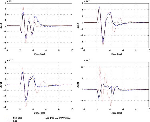
Table 8 displays the values of the simulation criteria for the second part of simulation.
| Second scenario | ITAE | % OV | % US | TS | FD |
|---|---|---|---|---|---|
| PSS | 0.007418 | 2.347815 | −2.32614 | 7.899106 | 18.6842 |
| MB-PSS | 0.004015 | 1.406393 | −2.20198 | 5.610774 | 15.4356 |
| MB-PSS and STATCOM | 0.003435 | 1.076406 | −1.63154 | 3.804895 | 14.9835 |
It is possible to remark on the performance of each of the three proposed systems by comparing the results of the simulations described in Tables 7 and 8. In both modes of operation, the criteria associated with the MB-PSS and STATCOM stabilizer system have the lowest values, indicating that this combination provides the optimal and most suitable performance. Maximum overshoot and undershoot of oscillations are one of the intended comparison criteria for the performance of the offered approaches. The lower the maximum overshoot and undershoot values, the more dynamically stable the system will be and the more power the transmission line will be able to transmit. The settling time or damping time of oscillations is an additional criterion for identifying the greater performance of one stabilizer over another. The faster the stabilizer can reduce the oscillations generated by disturbances, the more efficient it will be. In all instances, the MB-PSS and STATCOM combined system exhibited less overshoot, undershoot, and settling time than the other two systems.
6. Conclusion
In this research, a study was conducted to enhance the small signal stability of the power system by focusing on the optimal coordination of MB-PSS and STATCOM. The investigation was carried out on a standard four-machine and two area power system. To achieve the desired coordination, a modified version of the PSO algorithm was proposed, utilizing the ITAE criterion. Two scenarios were considered to evaluate the effectiveness of the proposed stability method under different operating conditions. In both scenarios, a three-phase fault with a duration of 200 ms was introduced in the communication line connecting the two areas. The performance of the proposed stability method was assessed by calculating measures such as overshoot, undershoot, settling time, and ITAE criteria. These values were compared with the results obtained from the application of PSS and MB-PSS stabilization methods. Simulation results demonstrated that the combined approach of MB-PSS and STATCOM outperformed the other two methods in terms of enhancing dynamic stability in the power system, exhibiting the lowest values for the evaluated criteria. In the first scenario, the ITAE values for the PSS, MB-PSS stabilization methods, and the proposed MB-PSS and STATCOM combined method were 0.002354, 0.001496, and 0.001242 p.u., respectively. In the second scenario, these values were 0.007418, 0.004015, and 0.003435 p.u., respectively. For future studies, the integration of renewable photovoltaic or wind farms with high power generation capacity into the power system can be explored. Additionally, the optimal coordination of power system stabilizers and FACTS devices can be investigated to further enhance the stability of the system.
Conflicts of Interest
The authors declare that they have no conflicts of interest.
Appendix
Speed converter parameters:
K1 = −1.759 × 10⁻³; K2 = 1.2739 × 10⁻⁴; K3 = 1.7823 × 10⁻²;
K4 = 80; K5 = 82; K6 = 161; K7 = 80.
Open Research
Data Availability
The data used to support the findings of this study are included within the paper.


