Static Equilibrium Characteristics of Full-Flow Staged Combustion Cycle Engine Under Different Propellants
Abstract
The full-flow staged combustion cycle (FFSC) engine is a promising liquid rocket propulsion system owing to its capacity for high specific impulse. The present study introduces an equilibrium model of the FFSC engine, utilizing the Raptor engine as a reference point and employing the discrete Newton iteration method to resolve the equilibrium equations in a fixed-point format. Under different propellants (LOX-LH2, LOX-LCH4, and LOX-kerosene), the static equilibrium characteristics of the FFSC engine were analyzed, and the following conclusions were drawn. The FFSC engine exhibited similar equilibrium results on the oxidizer side, with differences concentrated on the fuel side. Significant differences were identified between the three propellants in the regulation range of the FFSC engine. The regulation range of LOX-LH2 was wider than that of LOX-LCH4 primarily because of the variance in the molecular weight of the fuel-rich gas. Conversely, LOX-kerosene exhibited the narrowest regulatory range, which was attributed to the extremely low value of the oxidizer excess coefficient. The temperature management of preburners relies on regulating the oxidizer excess coefficient, necessitating adjustments to the valve components (main fuel valve (MFV), oxidizer preburner fuel valve (OPFV), and fuel preburner oxidizer valve). The differences among the three propellants were mainly concentrated on the MFV and OPFV.
1. Introduction
System modeling and simulation are indispensable for a staged combustion cycle engine as they empower engineers to make informed decisions during the initial phase of the design process. To achieve a higher specific impulse potential, the full-flow staged combustion cycle (FFSC) is essential because it integrates the advantages of both oxidizer-rich staged combustion (ORSC) and fuel-rich staged combustion (FRSC) [1]. The system modeling process of the FFSC presents significant challenges owing to the multitude of engine components, resulting in complex equilibrium characteristics. However, by balancing the various components of the engine, the FFSC can enhance the combustion chamber efficiency and turbine lifespan while simultaneously mitigating the challenges associated with turbopump sealing [2–4].
Equilibrium characteristic studies have long been conducted to predict and improve the performance of staged combustion cycle engines in a repeated manner with lower time and cost. A consistent research focus has been on static equilibrium characteristics, which describe the influential relationships among engine components in a stable state. A common approach to system modeling is to establish equilibrium equations for an engine, including directed graph, nodal element, and modular analysis methods [5, 6]. Based on these equations, the solution approaches include the approximate Newton iteration method, genetic algorithms, and particle swarm optimization algorithms [7–10]. In addition, with the development of simulation software, tools such as MATLAB Simulink and Simcenter Amesim have been employed for system simulation [11].
In recent years, there has been a notable emphasis on conducting comprehensive studies on the static equilibrium characteristics of both ORSC and FRSC systems. Naderi and Liang and Naderi, Guozhu, and Karimi [12, 13] developed a static model of the Space Shuttle Main Engine (SSME) for the thrust regulation analysis of the FRSC engine. Jihyoung et al. [14] investigated the SSME using diagnostic analysis during steady-state operation. Christoph [15] referenced the RD-120 engine to establish a steady model of the ORSC engine. Ramesh, Karimi, and Shahheidari [7] established the RD-180 engine model to explore the booster pump effect on the static equilibrium of the ORSC engine. In terms of static equilibrium studies of the FFSC, there is a scarcity of related research. Ping et al. [16, 17] constructed the RS-2100 engine model for examining the impact of the combustion chamber mixture ratio and preburner mixture ratio on the FFSC engine. Although this study introduces the system model, it does not provide a detailed description of the equilibrium equations governing the FFSC.
The success of the SpaceX Starship has propelled the FFSC cycle into the forefront as a highly promising staged combustion cycle. Previous FFSC engines include the RD-270, RS-2100, IPD, and Raptor engines, which used the propellants N2O4-UDMH, LOX-LH2, and LOX-LCH4, respectively [18, 19]. The selection of propellants for FFSC engines aligns with the prevailing trend favoring cryogenic liquid propellants in new generation launch vehicles, such as LOX-LH2, LOX-LCH4, and LOX-kerosene. In terms of their common advantages, the nontoxicity and low pollution of cryogenic liquid propellants provide unique advantages over conventional propellants, rendering them more suitable for environmental protection. Furthermore, these propellants exhibit high specific impulse and propulsive efficiency. In terms of their respective advantages, LOX-LH2 is well known for its exceptionally specific impulse, leading to enhanced thrust or extended flight distances for equivalent propellant masses. However, the low density of liquid hydrogen requires larger and heavier containers for transportation [20]. LOX-LCH4 holds the potential for in situ resource utilization on Mars. Meanwhile, liquid methane is safe to store for a long-term storage in space [21, 22]. Additionally, LOX-kerosene offers unique advantages in terms of storage and ease of handling. The high propellant density of kerosene enables a compact design of turbomachinery and minimal stage sizes [23]. Therefore, the selection of propellants such as LOX-LH2, LOX-LCH4, and LOX-kerosene shows great promise for application in FFSC engines. Burkhardt et al. [24] and Dresia et al. [25] evaluated the mass benefits of reusable launch vehicles equipped with FFSC engines using various propellant options. Nevertheless, the existing literature has yet to comprehensively discuss the static equilibrium characteristics of FFSC engines utilizing these propellants.
Several studies have been conducted on the static equilibrium characteristics of staged combustion-cycle engines. However, the absence of studies on the detailed equilibrium modeling of FFSC engines, along with comparisons between various propellant combinations and the static performance of FFSC engines, underscores a critical gap in the current research landscape. To fill this gap, it is necessary to comprehensively investigate the static equilibrium characteristics of the FFSC engine under different propellants. Such an investigation is indispensable for elucidating the system equilibrium characteristics and broadening the selection of propellant combinations for future FFSC engines.
The aim of the present study is to compare the static equilibrium characteristics of an FFSC engine with different propellants. These propellants, including LOX-LH2, LOX-LCH4, and LOX-kerosene, all have potential for use in FFSC engines. To address this objective, an equilibrium model for the FFSC engine was developed, considering the flow, pressure, and power equilibrium. The solution method employed the discrete Newton iteration method within a fixed-point formulation. A comparative analysis of the equilibrium outcomes of the FFSC engine under rated operating conditions was conducted, while also examining the impacts of the chemical equilibrium and pressure distribution on the system.
2. Mathematical Model
To establish the equilibrium model of the FFSC engine, the Raptor engine V2 version was utilized as a reference for the system structure. This choice was made because it is the only FFSC engine that is currently employed successfully in rocket flight applications.
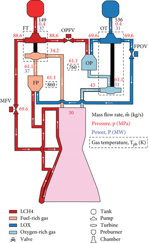
Figure 1 shows the Raptor V2 system, which includes a fuel turbopump (FT), an oxidizer turbopump (OT), a fuel-rich preburner (FP), an oxidizer-rich preburner (OP), a main fuel valve (MFV), an oxidizer-rich preburner fuel valve (OPFV), and a fuel-rich preburner oxygen valve (FPOV), cooling channel, and combustion chamber.
The Raptor engine has the following characteristics:
The most significant structural feature of the FFSC engine is that it has two preburners that are fuel- and oxidizer-rich. The FP generates the gas to drive the turbine for the fuel pump, while the OP generated the gas to drive the turbine for the oxidizer pump.
The OT is highly integrated, featuring an OP positioned between the oxidizer pump and turbine, with all three components integrated into the combustion chamber assembly. The oxidizer is pressurized by the oxidizer pump and directed into the preburner through the injector, rendering the pressure loss along the pipeline between the oxidizer pump outlet and the preburner injector negligible.
Meanwhile, a broad spectrum of engine thrust regulations can be achieved by controlling three valves: MFV, FPOV, and OPFV.
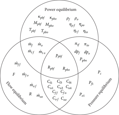
The equilibrium model of the FFSC engine requires consideration of the flow equilibrium, pressure equilibrium, and power equilibrium within the entire system. The mathematical models corresponding to these three types of equilibrium relationships will be introduced in the following sections.
Here, the gas properties and specific impulse can be obtained using the equilibrium combustion analysis software NASA CEA [26].
Notably, the propellant flows between the two preburners were mutually affected.
In the described equations, the gas properties of the preburner can be obtained using the NASA CEA. The gas and propellant flow rates were calculated using flow equilibrium equations. The turbine pressure ratio and pump head were calculated using the pressure equilibrium equations.
The relationships between the FFSC engine parameters are shown in Figure 2. Notably, Rpbf, Rpbo, and ppbf concurrently affect the power, flow, and pressure equilibrium, respectively. It is more convenient to solve the equations by selecting Rpbf, Rpbo, and ppbf as the variables.
3. Numerical Method
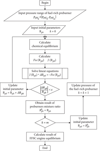
The equilibrium equations of the FFSC engine are complex nonlinear equations that require numerical methods for their solution. Traditional methods such as the Newton, Newton–Raphson, and fixed-point iteration methods are commonly employed. However, directly applying these methods to solve the equilibrium model of an FFSC engine often results in poor convergence and is a significant computational burden. To mitigate these challenges, a discrete Newton iteration method based on a fixed-point formulation was employed in the present study. This approach involved transforming the original equilibrium equations into a fixed-point form before initiating the iterative solution process. This choice was motivated by the superior convergence properties of nonlinear equations in the fixed-point form, along with the advantage of reducing the computational load by minimizing the number of equations to be solved iteratively.
Tables 1 and 2 list the performance parameters and pressure drop loss coefficients of the FFSC engine model, respectively. The integrated powerhead demonstrator engine served as the mixture ratio reference for the LOX-LH2 propellant, whereas the RD180 engine served as the mixture ratio reference for the LOX-kerosene propellant. These were selected because of their status as advanced-staged combustion cycle engines [29, 30]. The densities of the propellants were obtained by means of REFPROP.
| Parameters | LOX-LH2 | LOX-LCH4 | LOX-kerosene |
|---|---|---|---|
| Chamber pressure (MPa) | 30 | 30 | 30 |
| chamber mixture ratio | 6.4 | 3.6 | 2.7 |
| Engine thrust (KN) | 2230 | 2230 | 2230 |
| Fuel density (kg/m3) | 73 | 420 | 807 |
| Oxidizer density (kg/m3) | 1140 | 1140 | 1140 |
| Tank outlet pressure (MPa) | 0.4 | 0.4 | 0.4 |
| Specific impulse (N·s/kg) | 4036.35 | 3337.89 | 3246.45 |
| Coefficients | Value | Coefficients | Value | Coefficients | Value | Coefficients | Value | Coefficients | Value |
|---|---|---|---|---|---|---|---|---|---|
| Cf1 | 0.63 | Cf2 | 0 | Cf3 | 0.14 | Cff | 0.14 | Cfo | 0.14 |
| Co1 | 0 | Co2 | 0 | Co3 | 0.43 | Cof | 0.45 | Coo | 0.14 |
The Gibbs free energy minimization method was used in chemical equilibrium calculation, where the Gibbs free energy is minimized at chemical reaction equilibrium. The detailed process of solving chemical equilibrium was explained in Gordon’s literature [31]. This method treated each combustion species independently, eliminating the need for a predefined set of reactions.
4. Model Validation
To validate the model, published data from the NASA Space Flight were used as reference. For the Raptor V2 engine, a static equilibrium model of the FFSC engine was developed and validated. For this validation, the required input data presented in Table 3 were provided. The resulting output parameters were verified against the published data.
| Input parameter | Value | Unit |
|---|---|---|
| 685 | kg/s | |
| R | 3.6 | — |
| At | 0.04226 | m2 |
| pf1 | 0.4 | MPa |
| po1 | 0.4 | MPa |
| Ppbf | 61.1 | MPa |
The simulation results are listed in Table 4. The equilibrium equations used for the FFSC system yielded reasonably accurate results. Using the suggested equations for computing the pressure properties, the pump head and turbine pressure ratio were found to follow the expected trends. The precision of the gas temperature in the preburners confirmed the suitability of the introduced equation sets for this component. The calculation value of the turbopump power was sufficiently accurate.
| Symbol | Unit | Present data | Rocket data | Error (%) | |
|---|---|---|---|---|---|
| Pump | kg/s | 148.2 | 149 | −0.53 | |
| kg/s | 537.8 | 536 | 0.33 | ||
| Δpf | MPa | 88.28 | 88.2 | 0.09 | |
| Δpo | MPa | 69.25 | 69.2 | 0.07 | |
| Turbine | πtf | MPa | 1.7752 | 1.787 | −0.66 |
| πto | MPa | 1.4152 | 1.421 | −0.41 | |
| Preburner | Tpbf | K | 869.7 | 860 | 1.13 |
| Tpbo | K | 767.1 | 760 | 0.93 | |
| Turbopump | Pf | MW | 37.1 | 37 | 0.27 |
| Po | MW | 30.9 | 31 | −0.32 | |
| Thrust chamber | pc | MPa | 30.2 | 30 | 0.67 |
| F | MN | 2.292 | 2.23 | 2.78 | |
| Is | s | 344.5 | 332 | 3.77 | |
According to Equation (1), thrust and specific impulse were significantly influenced by factors such as mass flow rate, pressure, temperature, and other parameters within the FFSC system. This led to the error of thrust and specific impulse being an accumulation of errors in various component parameters, resulting in the largest error value in the simulation results for the thrust chamber. Current studies on system simulation of liquid rocket engines often considered calculation errors within 5% to be reasonable [32, 33]. Therefore, compared with the reference values, the simulation results for the thrust chamber were considered acceptable.
5. Results and Discussion
5.1. Equilibrium Results of FFSC Engine Under Rated Operating Conditions
In this section, the equilibrium results of the FFSC engine under rated operating conditions are presented. The results of three propellants (LOX-LH2, LOX-LCH4, and LOX-kerosene) were compared. The required system input data are listed in Tables 1 and 2. To compare the differences in turbopump system parameters, the equilibrium results of three propellants are presented in Table 5.
| Symbol | Unit | LOX-LH2 | LOX-LCH4 | LOX-kerosene | |
|---|---|---|---|---|---|
| Fuel turbopump system parameters | |||||
| Mass flow rates | mf | kg/s | 76.3 | 148.2 | 191 |
| mtf | kg/s | 127 | 174 | 188 | |
| Pressure parameters | Δpf | MPa | 88.2 | 88.2 | 88.2 |
| πtf | 1.78 | 1.78 | 1.78 | ||
| Chemical equilibrium parameters | αpbf | 0.116 | 0.0679 | 0.0154 | |
| Tpbf | K | 731 | 870 | 847 | |
| κpbf | 1.38 | 1.15 | 1.11 | ||
| Mpbf | g/mol | 3.51 | 17.4 | 28.1 | |
| Turbine power | gf | MW | 109 | 37.1 | 24.7 |
| Oxidizer turbopump system parameters | |||||
| Mass flow rates | mo | kg/s | 489 | 537.8 | 515 |
| mto | kg/s | 438 | 512 | 518 | |
| Pressure parameters | Δpo | MPa | 69.2 | 69.2 | 69.2 |
| πto | 1.42 | 1.42 | 1.42 | ||
| Chemical equilibrium parameters | αpbo | 19.6 | 15.4 | 18.8 | |
| Tpbo | K | 781 | 767 | 734 | |
| κpbo | 1.32 | 1.32 | 1.32 | ||
| Mpbo | g/mol | 30.3 | 31.4 | 31.9 | |
| Turbine power | gf | MW | 28.3 | 30.9 | 29.8 |
For the FFSC engine, the differences in mass flow rate, chemical equilibrium parameters, and turbine power were concentrated on the fuel side. This was because the chemical equilibrium parameters of the fuel-rich gas were similar to those of the fuel itself, whereas the physical properties of hydrogen, methane, and kerosene were significantly different. Owing to the similarity of the chemical equilibrium parameters of the oxidizer-rich gas to those of oxygen, the FFSC engine exhibited comparable turbopump system parameters on the oxidizer side.
For LOX-LH2, the fuel-rich turbine power (gf) was 194% and 341% higher than that of LOX-LCH4 and LOX-kerosene, respectively. According to the power equations of the turbine (11), the fuel-rich turbine power (gf) increased with mtf, Tpbf, and πtf, but decreased with increases in κpbo and Mpbf. Table 5 compares these five parameters for three propellants. It was shown that for LOX-LH2, only the molecular weight of fuel-rich gas (Mpbf) had a positive impact on increasing fuel-rich turbine power (gf). The Mpbf of LOX-LH2 was 79.8% and 87.5% lower than that of LOX-LCH4 and LOX-kerosene, respectively.
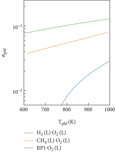
The oxidizer excess coefficient (OEC) is the ratio of the mixture mass ratio (oxidizer/fuel) to the stoichiometric mass ratio of propellants. For LOX-kerosene, the OEC of the FP (αpbf) was the lowest, being 77.26% and 86% lower than that of LOX-LCH4 and LOX-LH2, respectively. In accordance with the definition of the OEC, a smaller OEC value signifies a greater deviation between fuel-rich and complete combustion. Consequently, in the FP, LOX-kerosene exhibited the most pronounced deviation from complete combustion.
For LOX-LCH4, most of the data fell between those of LOX-LH2 and LOX-kerosene (Table 5. This is because the carbon content and molecular weight of methane fell between hydrogen and kerosene. The fuel-rich gas properties of LOX-LCH4 obtained by chemical equilibrium calculations were also between LOX-LH2 and LOX-kerosene.
5.2. Influence of Chemical Equilibrium
The chemical equilibrium in the preburners and the pressure distribution within the engine system directly impacted the equilibrium results of the FFSC engine. In this section, the influence of the chemical equilibrium on the preburners is presented. The results of the three propellants (LOX-LH2, LOX-LCH4, and LOX-kerosene) were compared. A comparison of the results requires consistency in the pressure distribution. The range of chamber and preburner pressure for engines using different propellants was maintained at 15–30 MPa and 20–62 MPa.
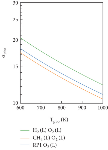
In Figure 4, the OEC of the preburners for the three propellants was obtained through a chemical equilibrium calculation. As shown in Figure 4(a), there was a significant difference in the OEC of the FP (αpbf) under three propellants. The LOX-kerosene had a significantly lower αpbf value than LOX-LCH4 and LOX-LH2. According to the definition of OEC, this suggested that the extent of deviation from complete combustion for LOX-kerosene in the FP was markedly higher than that for LOX-LCH4 and LOX-LH2. Owing to this considerable deviation, LOX-kerosene has a minimum temperature limit of 778 K, thus restricting the regulation range of FP temperatures. Figure 4(b) showed that three propellants exhibited similar variations in the OEC of the OP (αpbo). The LOX-LH2 had a slightly higher αpbo value than LOX-LCH4 and LOX-kerosene. However, the differences in αpbo among the three propellants were minimal compared to the variations in αpbf. This suggested that the extent of deviation from complete combustion for these propellants in the OP was also trending towards consistency.
Figures 5 and 6 show the chemical equilibrium temperatures of the preburners (Tpb) at different pressure distributions. It was found that Tpb decreased with the decrease in the chamber pressure (Pc) but increased with the decrease in the preburner pressure (Ppbf). This phenomenon was mainly attributed to the power equilibrium Equation (10). The chamber pressure (Pc) affected the outlet pressure of the turbines, leading to an increase in the pressure ratio of the turbines. To maintain the same power of turbines, it was necessary for the chemical equilibrium temperature to decrease. Similarly, the preburner pressure (Ppbf) affected the inlet pressure of the turbines, leading to a decrease in their pressure ratio. Finally, the chemical equilibrium temperature was increased to maintain the power supply.
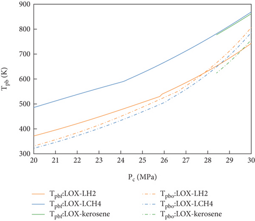
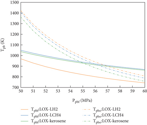
Under the same changes in the pressure parameter distribution, the chemical equilibrium temperatures (Tpb) of the preburners were compared for the three propellants. As shown in Figures 5 and 6, Tpbf of LOX-LH2 was significantly lower than that of LOX-LCH4 and LOX-kerosene. This phenomenon was mainly caused by differences in the fuel-rich gas properties. According to the turbine power Equation (11), a decrease in the gas molecular weight facilitated an increase in the turbine power. For LOX-LH2, the molecular weight of the fuel-rich gas was significantly lower than those of the other two propellants, leading to a lower chemical equilibrium temperature (Tpbf) to satisfy the demands of fuel-rich turbine power.
As shown in Figure 5, the solution range of LOX-kerosene was significantly smaller than those of LOX-LH2 and LOX-LCH4. This phenomenon was primarily caused by the inability to solve the equilibrium equations of the FFSC engine. For LOX-kerosene, the OEC of the FP limited the temperature range, leading to a mismatch between the power provided by the fuel-rich turbine and that required by the fuel pump.
Figure 7 shows the distribution nephogram of the equilibrium temperature at different pressure distributions. Throughout the entire pressure range, the equilibrium model of the FFSC engine was not solvable. When the chamber pressure (Pc) was kept constant, a higher preburner pressure (Ppbf) caused the temperature to exceed the temperature limit. Meanwhile, a lower preburner pressure (Ppbf) resulted in the inability to solve the equilibrium equations of the FFSC engine. Therefore, within a certain pressure range, the equilibrium model of FFSC engines can achieve equilibrium.
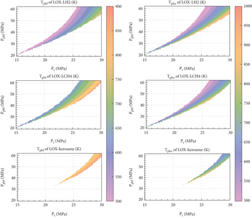
To compare the size of the pressure regulation range, the “pressure regulation ratio” was defined as the ratio of the colored area to the entire area, as shown in Figure 7. The pressure regulation ratios of LOX-LH2, LOX-LCH4, and LOX-kerosene were 21.4%, 19.1%, and 7.2%, respectively. It was found that the FFSC engines using LOX-LH2 had the widest accessible pressure regulation range due to its low FP temperature (Tpbf). The FFSC engines using LOX-kerosene had the narrowest accessible pressure-regulation range because the FP of LOX-kerosene had a minimum temperature limit of 778 K.
5.3. Influence of Pressure Distribution
In this section, the influence of the pressure distribution within the engine system on the equilibrium results of the FFSC engine is presented. The results of the three propellants were compared. For this purpose, it was important to maintain a consistent equilibrium temperature. As such, the regulation of the valves (MFV, FPOV, and OPFV) must be considered. By adjusting the pressure drop loss of the valves, the fuel-rich and OP temperatures were controlled at 857 K and 761 K, respectively.
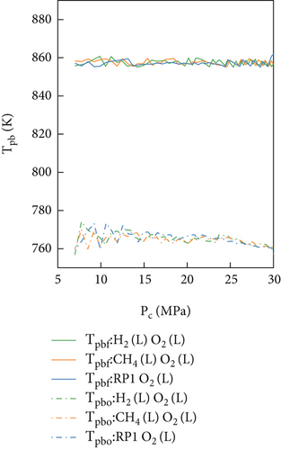
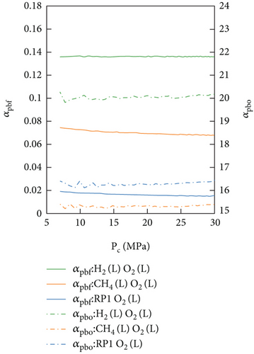
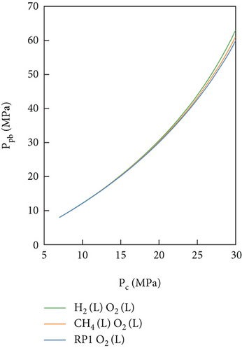
In theory, the chemical equilibrium temperature in preburners (Tpb) would mainly be affected by the OEC (αpb) and pressure (Ppb). Owing to the influence of the pressure equilibrium equations, the preburner pressure decreased as the chamber pressure decreased. Hence, only the OEC of the preburners remained constant. Figure 8 shows the relationship between these three parameters (Tpb, αpb, Ppb) and chamber pressure (Pc). Maintaining the consistency in the OEC of the preburners was found to be a feasible way to maintain Tpb. In the FFSC engine, the chemical equilibrium temperature in the preburners was mainly affected by the OEC, and the influence of the pressure could be neglected.
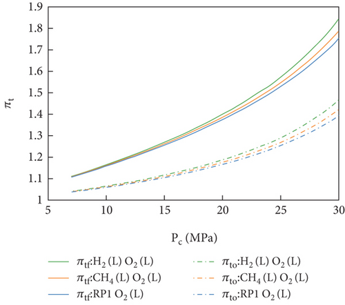
The turbine pressure ratio (πt) and pump head (Δp) were identified as the key pressure parameters affecting the turbopump system. As shown in Figures 9 and 10, both the turbine pressure ratio (πt) and pump head (Δp) decreased with chamber pressure (Pc). This phenomenon was largely caused by the equilibrium equations of the FFSC engine. According to the flow equilibrium Equations (1)–(4), a decrease in the chamber pressure resulted in a decrease in the turbine gas and pump flow rates, leading to a decrease in the turbopump power. For the turbines, the turbine pressure ratio (πt) should be reduced to maintain these low power supply. Additionally, according to the pressure equilibrium Equation (6), a decrease in chamber pressure resulted in a decrease in the outlet pressure of pumps, leading to a decrease in the pump head (Δp).
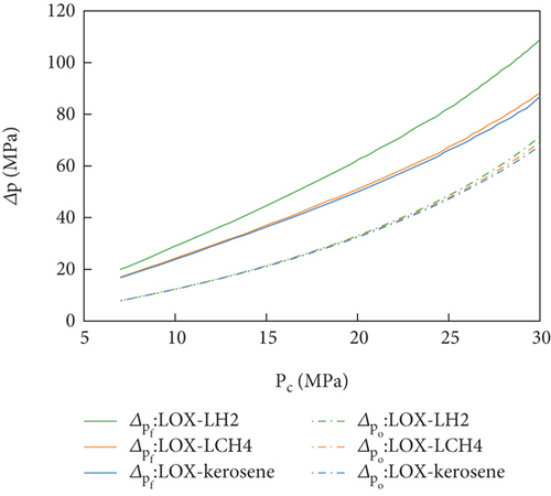
Under the same equilibrium temperature, the turbopump pressures were compared for the three propellants. As shown in Figure 10, the fuel pump head of LOX-LH2 was significantly higher than that of LOX-LCH4 and LOX-kerosene. This phenomenon was mainly caused by the difference in the fuel-rich turbine power. For LOX-LH2, the turbine was driven by the fuel-rich gas with a significantly low molecular weight, resulting in a high power output. According to the power equilibrium Equations (10)–(12), to achieve power equilibrium between the fuel pump and fuel-rich turbine, it was necessary to increase the fuel pump head, resulting in an increase in the fuel pump power.
The valve components (MFV, OPFV, and FPOV) of the FFSC engine were found to play a significant role in maintaining consistency in the chemical equilibrium temperature. Figure 11 shows a comparison of the pressure drops across the three valve components. It was found that, for MFV and OPFV, the pressure drops of LOX-LH2 were significantly higher than LOX-LCH4 and LOX-kerosene. However, for the FPOV, the pressure drops of the three propellants were almost coincident.
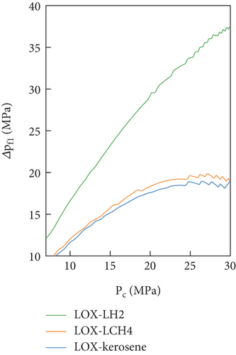
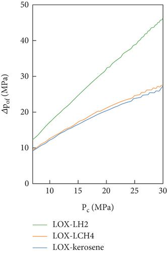
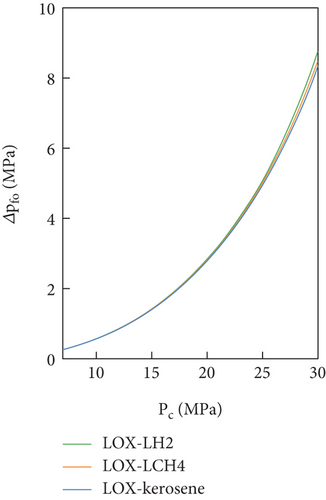
These findings were attributed to the pump head. Notably, the valve components (MFV, OPFV, and FPOV) adjusted the pressure drop between the pumps and preburners. As the three propellants had similar preburner pressure, the difference in pressure drop of valve components was mainly affected by the pump head. The MFV and FPOV were connected to the fuel pump, while the FPOV was connected to the oxidizer pump. Therefore, the variation in pressure drop of valve components was consistent with the changes in their corresponding pump head. The high value of the fuel pump pressure head for LOX-LH2 led to a higher pressure drop in the MFV and FPOV. Simultaneously, the oxidizer pump heads of three propellants were similar, resulting in similar pressure drops of the FPOV.
6. Conclusion
- 1.
Under three propellants (LOX-LH2, LOX-LCH4, and LOX-kerosene), the FFSC engine exhibited similar equilibrium results on the oxidizer side, with differences concentrated on the fuel side.
- 2.
The chemical equilibrium temperature decreased with the decrease in chamber pressure but increased with the decrease in preburner pressure. This phenomenon could be attributed to the power equilibrium of the FFSC engines.
- 3.
Under three propellants (LOX-LH2, LOX-LCH4, and LOX-kerosene), the FFSC engine exhibited different regulation ranges to achieve system equilibrium. The regulation range of LOX-LH2 was wider than that of LOX-LCH4, which was attributed to differences in the molecular weight of the fuel-rich gas. However, LOX-kerosene had the narrowest regulation range owing to its extremely low OEC.
- 4.
The temperature control of the preburners depends on regulating the OEC, which relies on adjusting the valve components (MFV, OPFV, and FPOV). The differences between the three propellants were primarily manifested in the MFV and OPFV. Notably, the pressure drop of LOX-LH2 was the most pronounced and rapid and was largely influenced by its elevated fuel-rich turbine power.
Nomenclature
-
- The following symbols are used in this paper:
-
-
- At
-
- nozzle throat area (m2)
-
- Cff
-
- pressure drop loss coefficient between fuel injector and the fuel-rich preburner
-
- Coo
-
- pressure drop loss coefficient between the oxidizer injector and the oxidizer-rich preburner
-
- Cof
-
- pressure drop loss coefficient between the fuel pump and the oxidizer-rich preburner
-
- Cfo
-
- pressure drop loss coefficient between the oxidizer pump and the fuel-rich preburner
-
- Cf1
-
- pressure drop loss coefficient between the fuel pump and fuel injector of the fuel-rich preburner
-
- Co1
-
- pressure drop loss coefficient between the oxidizer pump and oxidizer injector of the oxidizer-rich preburner
-
- Cf2
-
- pressure drop loss coefficient between the fuel-rich preburner and the fuel-rich turbine
-
- Co2
-
- pressure drop loss coefficient between the oxidizer-rich preburner and the oxidizer-rich turbine
-
- Cf3
-
- pressure drop loss coefficient between the fuel-rich turbine and the combustion chamber
-
- Co3
-
- pressure drop loss coefficient between the oxidizer-rich turbine and the combustion chamber
-
- F
-
- rocket engine thrust (N)
-
- Fu
-
- equilibrium equation in fixed-point form
-
- Gf
-
- equilibrium equation in fixed-point form on the side of the fuel-rich preburner
-
- Go
-
- equilibrium equation in fixed-point form on the side of the oxidizer-rich preburner
-
- gf
-
- fuel-rich turbine power (W)
-
- go
-
- oxidizer-rich turbine power (W)
-
- Is
-
- specific impulse of rocket engine (N·s/kg)
-
- Mpb
-
- molecular weight of gas (g/mol)
-
- Mpbf
-
- molecular weight of fuel-rich gas (g/mol)
-
- Mpbo
-
- molecular weight of oxidizer-rich gas (g/mol)
-
-
- total propellant flow rate (kg/s)
-
-
- fuel pump flow rate (kg/s)
-
-
- oxidizer pump flow rate (kg/s)
-
-
- fuel-rich turbine gas flow rate (kg/s)
-
-
- oxidizer-rich turbine gas flow rate (kg/s)
-
-
- fuel flow rate of the fuel-rich preburner (kg/s)
-
-
- oxidizer flow rate of the fuel-rich preburner (kg/s)
-
-
- fuel flow rate of the oxidizer-rich preburner (kg/s)
-
-
- oxidizer flow rate of the oxidizer-rich preburner (kg/s)
-
- Pf
-
- fuel turbopump power (W)
-
- Po
-
- oxidizer turbopump power (W)
-
- pf
-
- fuel pump power (W)
-
- po
-
- oxidizer pump power (W)
-
- ppbf
-
- fuel-rich preburner pressure (Pa)
-
- ppbo
-
- oxidizer-rich preburner pressure (Pa)
-
- pf1
-
- inlet pressure of the fuel pump (Pa)
-
- po1
-
- inlet pressure of the oxidizer pump (Pa)
-
- pf2
-
- outlet pressure of the fuel pump (Pa)
-
- po2
-
- outlet pressure of the oxidizer pump (Pa)
-
- pf3
-
- inlet pressure of the fuel-rich turbine (Pa)
-
- po3
-
- inlet pressure of the oxidizer-rich turbine (Pa)
-
- pf4
-
- outlet pressure of the fuel-rich turbine (Pa)
-
- po4
-
- outlet pressure of the oxidizer-rich turbine (Pa)
-
- pc
-
- chamber pressure (Pa)
-
- R
-
- mixture ratio of the rocket engine
-
- Rpbf
-
- mixture ratio of the fuel-rich preburner
-
- Rpbo
-
- mixture ratio of the oxidizer-rich preburner
-
- Rpb
-
- mixture ratio of the fuel-rich preburner
-
- R0
-
- gas constant (8.314 J/mol K)
-
- Rc
-
- gas constant of chamber (J/(kg·K))
-
- Tc
-
- chemical equilibrium temperature of chamber (K)
-
- Tpb
-
- chemical equilibrium temperature (K)
-
- Tpbf
-
- chemical equilibrium temperature of the fuel-rich preburner (K)
-
- Tpbo
-
- chemical equilibrium temperature of the oxidizer-rich preburner (K)
-
- Δp
-
- pump head (Pa)
-
- Δpf
-
- fuel pump head (Pa)
-
- Δpo
-
- oxidizer pump head (Pa)
-
- Δpf1
-
- pressure drop loss between the fuel pump and fuel injector of the fuel-rich preburner
-
- Δpof
-
- pressure drop loss between the fuel pump and the oxidizer-rich preburner
-
- Δpfo
-
- pressure drop loss coefficient between the oxidizer pump and the fuel-rich preburner
-
- αpb
-
- oxidizer excess coefficient of preburners
-
- αpbf
-
- oxidizer excess coefficient of fuel-rich preburner
-
- αpbo
-
- oxidizer excess coefficient of oxidizer-rich preburner
-
- ηc
-
- chamber efficiency
-
- ηtf
-
- fuel-rich turbine efficiency
-
- ηto
-
- oxidizer-rich turbine efficiency
-
- ηpf
-
- fuel pump efficiency
-
- ηpo
-
- oxidizer pump efficiency
-
- κc
-
- specific heat ratio of chamber gas
-
- κpb
-
- specific heat ratio of gas
-
- κpbf
-
- specific heat ratio of the fuel-rich gas
-
- κpbo
-
- specific heat ratio of the oxidizer-rich gas
-
- πtf
-
- fuel-rich turbine pressure ratio
-
- πto
-
- oxidizer-rich turbine pressure ratio
-
- ρf
-
- fuel density (kg/m3)
-
- ρo
-
- oxidizer density (kg/m3)
Conflicts of Interest
The authors declare no conflicts of interest.
Funding
The authors received no specific funding for this work.
Open Research
Data Availability Statement
All data, models, or codes that support the findings of this study are available from the corresponding author upon reasonable request.


