Event-Triggered Adaptive Neural Network Backstepping Sliding Fault-Tolerant Control of Spacecraft Formation Flying With Input Saturation
Abstract
This study explores the challenge of tracking control for spacecraft formation flying (SFF) in the presence of dynamic uncertainties and external perturbations. Firstly, sliding mode control combined with backstepping control is used to address saturation issues. Then, neural networks, minimal parameter learning, and adaptive control are integrated to handle dynamic uncertainties and actuator failures. To alleviate the communication load, an event-triggered mechanism is ultimately implemented, which leads to the development of an adaptive sliding mode fault-tolerant control algorithm based on an event-triggered neural network. This control architecture achieves significant advancements over traditional techniques: (1) ensuring system robustness and adaptability in complex scenarios with uncertain system dynamics and external disturbances, effectively counteracting actuator failures and input saturation issues; (2) significantly reducing transmission and computational burdens in resource-limited networked systems through the adoption of event-triggered control (ETC) mechanisms; (3) achieving high-precision tracking performance for SFF without relying on prior knowledge of the system’s inherent dynamics, environmental disturbances, or potential actuator deficiencies. The Lyapunov approach is utilized to confirm the closed-loop system’s boundedness. Finally, the proposed method’s efficacy is confirmed via simulations with a two-satellite formation.
1. Introduction
Spacecraft formation flying (SFF) has garnered significant attention because it offers substantial design cost benefits, increased reliability, and greater flexibility compared to traditional single spacecraft configurations [1]. Innovative formation missions, such as TanDEM-X/TerraSAR-X and PRISMA, have demonstrated their capability in executing a range of tasks, including surveillance, terrain mapping, and high-resolution imaging [2]. The control of formation configurations in operational SFF systems confronts complex challenges, such as task transition management, avoidance of configuration divergence, and space disturbance-induced perturbations like atmospheric drag and solar-lunar gravitational forces [3]. Consequently, formation control has become a pivotal area of aerospace research [3–7].
Addressing the inherent system uncertainties, such as satellite state changes and external disturbances, is crucial for maintaining efficient formation flight. Various control strategies, including robust [8, 9], adaptive [10, 11], sliding mode [12, 13], and optimal control [14, 15], have been developed to navigate these challenges. Notably, sliding mode control (SMC) has been extensively utilized due to its robustness against model uncertainties [10, 12, 13]. Despite SMC’s advantages, limitations such as its slow convergence rate and dependency on accurate disturbance information have spurred research into the integration of intelligent control technologies, including neural networks [16, 17], expert systems [18, 19], and fuzzy logic [20, 21]. This integration has delivered novel solutions to surmount these limitations and significantly enhance control system performance. Recent advancements involve leveraging neural networks to address uncertainties within spacecraft systems [22, 23], with Chebyshev neural networks demonstrating rapid and precise management of uncertainties, actuator faults, and external disturbances in spacecraft attitude control [24, 25]. Addressing the intricate issues posed by space disturbances and thruster malfunctions, a neural network-based control strategy utilizing a prescribed performance function and a novel learning-based approach using a nonsingular terminal SMC law have been developed, ensuring errors in positional tracking remain within predetermined performance bounds [26]. For spacecraft performing autonomous maneuvers [27], RBFNNs have been instrumental in adaptively counteracting model uncertainties. Moreover, Chebyshev neural networks have been employed to manage actuator saturation effectively, enhancing practical system performance [24]. Despite these advances in addressing disturbances, uncertainties, and system performance [25–27], the computational constraints of spacecraft have not been fully accounted for. High computational loads and slow convergence rates may fall short of real mission demands. Therefore, optimization of the neural network models becomes paramount. Research has led to matrix two-norm optimization for weight parameter reduction and enhanced convergence speeds [28], as well as a formula for real-time computation of time-varying matrix square roots, increasing computational efficiency [16]. Specifically, the fast time-varying neural network (FTZNN) manifests superior convergence rates over traditional ZNN models, offering distinct advantages for time-varying matrix square root challenges. Furthermore, fixed-structure RBFNN models have shown promising results for online learning, presenting a robust alternative to adaptive models that rely on instant parameter adjustments [29].
Input saturation in formation flight control, a consequence of the physical constraints on actuator power and response, can result in peak output and energy spikes, severely impacting the reliability of small satellites in particular and increasing the risk of failure [30, 31]. Adaptive control methods informed by neural network approximations have been developed to address attitude control issues arising from input saturation [32]. To improve tracking performance, a dead-zone operator-based model and adaptive techniques have been employed to overcome the challenges posed by the nondifferentiable nature of the saturation model [33]. To guarantee system stability, input saturation has been treated as a disturbance [34]. Extensive research has also been conducted on auxiliary design systems [12, 35–37], with works addressing actuator saturation through non-SMC, antisaturation compensators, and supplementary systems [12]. The backstepping technique has gained attention for its versatile approach to input saturation concerns [38], utilizing the principles of Lyapunov stability to simplify control design [39, 40]. Satellites enduring extended space conditions encounter challenges like space radiation and micrometeoroid strikes, leading to substantial actuator degradation. Developing fault-tolerant control methodologies has thus become a pressing priority to prevent instabilities in spacecraft formations. Actuator anomalies, namely, loss of effectiveness (LOE) and bias faults, have become focal points in formation preservation efforts [41–43]. However, the control solutions offered in [41, 42] depend on detailed knowledge of satellite relative motion models, with an assumed lower threshold for LOE faults as posited in [43]. A new study on fuzzy fault-tolerant control for nontriangular structure nonlinear systems, which bypasses these constraints, was initiated in [44]. Despite previous methodologies adeptly addressing actuator flaws and limitations, they have not adequately tackled the reduction of mechanical wear on actuators, a crucial factor in minimizing failure rates. The event-triggered control (ETC) paradigm offers a conservative actuator operation strategy, activating control only when specific conditions are met [45–48]. ETC has not only optimized actuator efficiency by reducing operational frequency but has also played a key role in stabilizing spacecraft formations [49, 50], reorganizing unmanned aerial vehicle formations [51], and directing maritime surface vessel trajectory control [52].
- 1.
Compared to [41–43], our approach addresses several common issues encountered in actual on-orbit operations, including model uncertainties, external disturbances, actuator malfunctions, input saturation, and restricted Moreover, our method achieves stable tracking performance without relying on prior knowledge of the SFF system dynamics, external disturbances, or actuator failures, demonstrating enhanced adaptability. Additionally, the handling of saturation effects reduces chattering compared to traditional saturation functions.
- 2.
Unlike [25–27], this study integrates neural networks with a minimal parameter learning algorithm to offer an efficient and practical control solution for SFF configuration. This approach significantly reduces the number of online learning parameters. Additionally, it effectively manages uncertainties without relying on common uncertainty-related assumptions, enhancing overall robustness and performance.
- 3.
Compared to time-triggered methods [49, 50, 53], this study is the first to propose an event-triggered mechanism-based adaptive neural network backstepping sliding mode fault-tolerant control method for the SFF system. This approach reduces the frequency of control command transmissions and the number of actuator engagements, effectively extending the system’s lifespan. This method significantly optimizes the performance of resource-limited networked systems and provides a robust solution for future SFF missions.
The structure of the paper is as follows: Section 2 introduces the problem formulation and background knowledge. Section 3 covers the controller design and stability analysis. Section 4 demonstrates simulation outcomes to verify the effectiveness of the proposed approach. Lastly, Section 5 wraps up the paper.
2. Preliminary and System Description
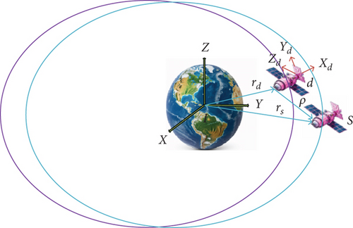
Consider the two spacecrafts depicted in Figure 1, undertaking orbiting flights around the Earth. The tracking spacecraft s and target spacecraft d (passive) are analyzed using two coordinate systems: Earth-centered inertial (ECI) and local vertical local horizontal (LVLH). In the LVLH frame, centered at the target spacecraft, the Xd axis points radially towards the tracking spacecraft, the Zd axis is perpendicular to the orbital plane along the angular momentum direction, and the Yd axis is orthogonal to both Xd and Zd, forming a right-handed Cartesian system.
Remark 1. An LOE fault, also known as a multiplicative fault, and a bias fault, referred to as an additive fault, are both considered. In this paper, ϱi = 1 and σi = 0 indicate that the SFF is free of faults; 0 < ϱi < 1 and σi = 0 signifies that the SFF is affected by an LOE fault in the actuator; and ϱi = 0 represents a total LOE of the SFF actuator. In this research, we are considering the scenario where ϱi ≠ 0. This would render the SFF uncontrollable.
Remark 2. The description of actuator faults in SFF systems, as depicted in Expression (9), draws from references [20, 41–43]. An LOE fault signifies uncertainties in the actuator gain under faulty conditions, while a bias fault accounts for errors in the control input channel. It is important to note that reference [42] focuses solely on the LOE fault ϱi, whereas reference [43] addresses bias faults exclusively. Meanwhile, reference [44] examines two fault types—an underlying fault and an LOE fault—yet assumes prior knowledge of the fault ϱi. In contrast, in this study, both ϱi and σi are not predetermined in the control design, enhancing the comprehensiveness and generality of our approach.
In practical scenarios, due to constraints in spacecraft actuator capabilities, prescribed control input commands are subject to saturation limitations.
For the ease of discussing control methodologies for SFF, some assumptions and lemmas are considered.
Assumption 1. The model parameter ms is unknown.
Assumption 2. The disturbances di and bias faults σi are constrained by and.
Assumption 3. The reference signals xd, yd and zd as well as and are bounded.
Lemma 1 (see [54].)Consider a dynamic system described by , where and are constants greater than zero and is a function that remains nonnegative. For any t ≥ 0, given that the initial value is both bounded and nonnegative, it follows that will also be nonnegative.
Lemma 2 (see [55].)States that for scalars ς ∈ ℝ and ∅∈ℝ, the inequality ς∅≤(|ς|nνn)/n + (|∅|m)/mνn holds, where ∅>1 are constants satisfying (n − 1)(m − 1) = 1.
Lemma 4 (see [57].)For a nonlinear function d(x): Rn⟶R defined over a compact set Ωx ∈ Rn, there is an NN W∗Th(x) such that for any given scalar η > 0
3. Controller Design and Stability Analysis
3.1. Controller Without ETC
Theorem 1. For a nonlinear dynamic system with input saturation and dynamic uncertainties, the closed-loop system’s stability is ensured, and the tracking error asymptotically approaches zero when a sliding surface, as defined in Equation (26), is selected, and backstepping SMC is designed according to the specifications in Equation (27).
Proof 1. The Lyapunov function V2 is defined as
Upon differentiating Equation (28) and utilizing Equations (21) and (24)–(27), we have
Upon differentiating Equation (28) and utilizing the relationships provided in Equations (21) and (24)–(27), we obtain the following result under Assumption 1. Provided that the disturbance bound satisfies the inequality , we can deduct from Equation (29) that is nonpositive, that is, . Therefore, this implies the stability of the closed-loop system as ensured by the backstepping SMC methodology.
Furthermore, due to the properties of ϱ, there exists an unknown constant φ > 0 such that
The RBFNN is applied to approximate the dynamic uncertainties , with the output vector represented as
The minimum parameter learning approach of the neural network is employed for . Let , ϕ is a positive real number, denotes the online estimated value of ϕ, and the learning error is given by.
The control law is redesigned as
Theorem 2. In a nonlinear relative dynamics system characterized by input saturation, dynamical uncertainties, and actuator faults, as described in Equation (11), the stability of the closed-loop system can be achieved by selecting an appropriate sliding surface as expressed in Equation (22) and devising a controller in line with Equation (32). The complete dynamic uncertainties of the spacecraft are estimated via Equation (31), while the adaptation laws are established in accordance with Equations (33)–(35). Under this framework, the tracking errors are assured to asymptotically converge to zero.
Proof 2. We propose the subsequent Lyapunov function for the SFF tracking control architecture.
By differentiating Equation (36) and substituting Equations (23)–(25), we get
From Lemma 3, we can obtain
Substituting the adaptation laws (Equations (33)–(35)) into Equation (38) yields leads to
Using Lemma 2, we have
Substituting Equations (40)–(42) into Equation (39) yields
Solving Equation (43), one obtains
Thus, V3 is bounded and . This indicates that are also bounded as per Equation (29), meaning
For the convenience of subsequent calculations, we assume that Λ is a sufficiently large positive number.
Thus,
For Equation (18), since c1 and c2 are positive definite matrices, and λ1, λ2 are as follows:
From Equations (20), (35), and (36), we obtain
Considering the bounded nature of , it can readily be deduced that are also bounded. From this, one can infer the boundedness of the term u. Clearly, all signals of the closed-loop control system are bounded.
Remark 3. With the RBFNN approximator, substituting control law Equation (26) into Equation (27) results in Equation (48). However, with the adoption of the RBFNN approximator, the substitution of control law Equation (32) into Equation (24) results in Equation (50). A comparison between Equations (49) and (50) reveals that the uncertainty term of the system has been altered from to upon the employment of the RBFNN approximator. The RBFNN approximator contributes to the compensation of the dynamic uncertainties within the system. When approaches , the RBFNN approximator can reduce the control gain from to , thereby compensating for system uncertainties and reducing the chattering phenomenon.
3.2. Controller With ETC
To diminish the frequency of transmission and actuator execution, an event-triggered network control system is introduced, building upon the foundation of the previous section. The architecture of the system is uncomplicated, which simplifies the control scheme design.
When the measurement error satisfies the condition , the controller will maintain its current input until transitions to the range , at which point the controller’s input will experience a step change.
Theorem 3. Given the dynamic Equation (11), the adaptive laws (33)–(35), and the event-driven control approach (51), the system exhibits asymptotic stability. Moreover, all signals in the system are guaranteed to be ultimately bounded and consistent, and Zeno behavior is effectively prevented.
Proof 3. From the ETC scheme Equation (51), we can obtain
Considering a Lyapunov equation and differentiating it can yield:
By substituting control input Equation (51) and the adaptive control law Equations (33)–(35) into the aforementioned expression, it comes to the result that
Similar to the above proof, the system remains bounded in the end.
The subsequent analysis will demonstrate the existence of a positive minimal time interval between any two successive triggering moments, thus ensuring that Zeno behavior is precluded within the system and .
In the definition of the event-triggering condition, the trigger heavily relies on the control input. A positive interval exists between any two successive instants when the control input changes continuously, given that , and the magnitude of stays within the bounds of ℏ. However, incorporates the discontinuous function sgn(s), leading to a noncontinuous control input, which in turn could result in continuous triggering of the sampling mechanism, precluding the assurance of a positive interval of time between triggers. Consequently, the initial step necessitates the eradication of the discontinuous elements from the control input function. This has been successfully accomplished by substituting the discontinuous function with a continuous counterpart and imposing certain restrictions as additional conditions.
Substitute sgn(s) into the continuous function Θ(si) = si/(|si| + δ), δ > 0 and the setΙ, defined.
as . It can be obtained that
And we can derive the derivative of as
The functions are continuous in a compact set Ωx.
The derivative of Θ(si) is given as
It is clear that . Thus, Θ(si) is continuous. Then, is bounded within Ωx and so is . is designed as
We can derive that Tk = tk+1 − tk ≥ ℏi/η from the properties of continuous . Therefore, we can infer the existence of an upper limit that fulfills the condition T = ℏi/η between each successive event-triggering moment.
Remark 4. The analysis has shown that the ETC strategy presented in this study successfully guarantees the asymptotic stability of the closed-loop system and substantially decreases the communication frequency between controllers and actuators, as well as decreasing the demand for transmission bandwidth. In the design of control systems, this strategy is particularly suitable for scenarios where there are constraints on resources and where a reduction in the frequency of control execution is necessary to maintain system stability. Through the carefully designed event-triggered mechanism, a more efficient control scheduling can be realized, thereby maximizing the effective utilization of resources.
4. Simulation Results
This section presents simulation results to validate the efficacy of the proposed control method. The initial orbital parameters of the two satellites are shown in Table 1.
| Orbital parameters | Parameter value of satellite d | Parameter value of satellite s |
|---|---|---|
| Semi-major axis | 7256.14 km | 7256.14 km |
| Eccentricity | 0.001 | 0.001 |
| Orbital inclination | 53° | 53° |
| Argument of perigee | 120° | 120° |
| Right ascension of ascending node | 30° | 30° |
| Mean anomaly | 5° | 5.004° |
The mass of satellite s is 60 kg, which is in the same orbit as satellite d, and the two satellites are in a back-and-forth orbit. To realize the forced circular flying-around of two satellites in the VVLH coordinate system, the flying-around parameters are shown in Table 2.
| Flying-around parameters | Value |
|---|---|
| Flying-around radius | 40 m |
| Angle θx of flying-around surface | 90° |
| Angle θz of flying-around surface | 30° |
| Initial phase angle | 0° |
| Flying-around period | 180 s |
To showcase the effectiveness of our proposed control scheme under the combined effects of uncertain dynamics, external disturbances, input saturations, and actuator faults (SFF), we compared our ETC approach with a continuous control strategy. For the continuous control scenario, the control law is defined by Equation (30), with the adaptive laws specified in Equations (31)–(33). The design parameters and initial conditions used were consistent with those in our control law design, as shown in Table 3.
| Index | Item | Value |
|---|---|---|
| Design parameters | ms, md | 60 kg, 60 kg |
| c1 | Diag (0.4, 0.4, 0.4) | |
| c2 | Diag (0.35, 0.35, 0.35) | |
| μ | Diag (1,1,0,77) | |
| ci | (0.2, 0.9, 0.25, 0.245, 0.2, 0.8) | |
| bi | 8 | |
| k | Diag (1.2, 1.2, 1.2) | |
| χ | 0.1 | |
| ℏ | (0.1; 0.1; 0.1) | |
| Γ1γ1 | 20, 0.2 | |
| Γ2γ2 | 0.1, 0.1 | |
| Γ3γ3 | 0.5, 0.002 | |
| δ | 0.01 | |
| X(0) | (60; −80; 50) | |
| (1; 2; 1) | ||
| ui,max, u1i,max | 150 Nm, 150 Nm | |
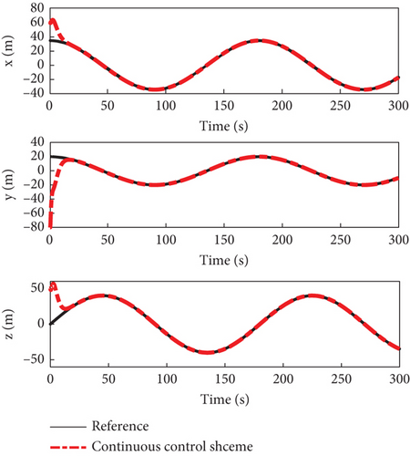
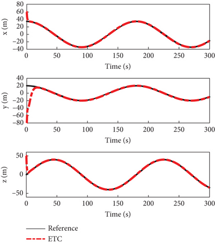
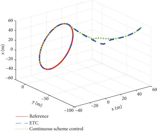
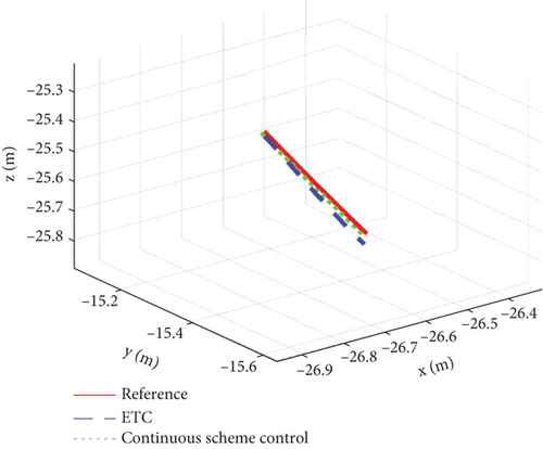
Figures 2, 3, 4, 5, 6, 7, 8, and 9 present the simulation results comparing the proposed ETC scheme to the continuous control strategy. As shown in Figures 2 and 3, both the ETC scheme and the continuous control method effectively enable the SFF to track the reference trajectory. This performance is maintained despite challenges such as time-varying uncertainties, input saturations, and actuator faults. However, the stabilization times for the ETC scheme are, respectively, 9, 21, and 11 s, whereas for the continuous control scheme, they are 20 s, 24 s, and 22 s, demonstrating faster stabilization speeds for the ETC scheme.
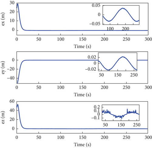
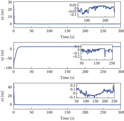
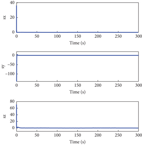
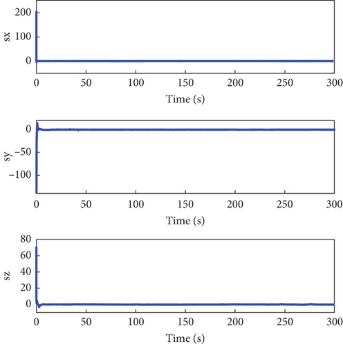
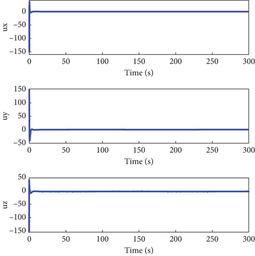
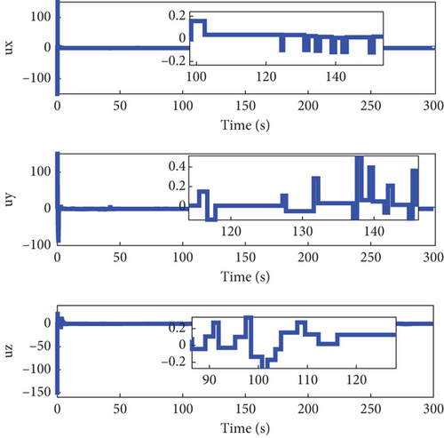
Figures 4 and 5 showcase the historical curves of the relative position error e and the sliding mode surface, showing that the position error e remains bounded under both fault-tolerant control strategies. The accuracy of the two control strategies is approximately the same, each maintaining a precision within the ranges of 10−2, 10−2, and 10−1. Figure 6 illustrates the variation of the control force u, u1 under both methods, demonstrating that both strategies effectively maintain the input u, u1 within the saturation limit of 150 Nm.
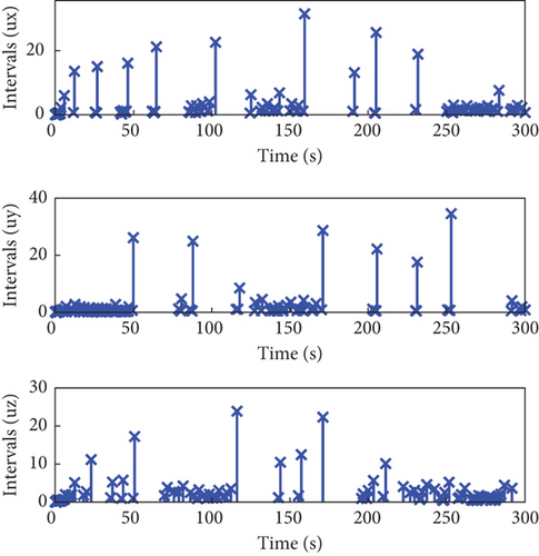
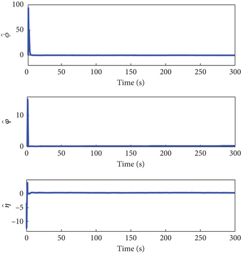
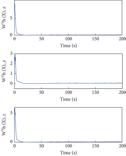
The total number of events in the channel u1 is 689, 228, and 190, respectively, which stands in stark contrast to the 30,001 events triggered under the continuous control method. This indicates that using our proposed ETC method significantly reduces the number of controller executions. Additionally, Figure 7 illustrates the triggering instances and intervals, showing that control commands u1i, i = x, y, z are not transmitted indefinitely within a short period. Figures 8 and 9 confirm that u, u1 remains bounded.
These findings confirm that all signals within the SFF closed-loop tracking control system remain bounded, as demonstrated in Theorem 3. Consequently, it can be inferred that our proposed control scheme effectively manages the SFF, even in the presence of dynamic uncertainties, external disturbances, input limitations, and actuator faults.
5. Conclusions
In the research presented within this paper, an event-triggered neural network adaptive backstepping sliding mode fault-tolerant control scheme, suitable for the challenging conditions of uncertain dynamics and external disturbances affecting SFF, has been proposed. Through the application of model transformation techniques and the implementation of a backstepping control system, issues associated with actuator saturation are aptly addressed. The combination of SMC with a neural network and a minimal parameter learning algorithm significantly enhances the system’s adaptability to uncertain dynamics and its tolerance to external interferences. Actuator usage frequency is thereby reduced, mitigating mechanical wear and obviating the need for prior knowledge of the system’s dynamics to ensure the SFF’s stable tracking. Our theoretical analysis and simulation studies have verified that all closed-loop control signals remain bounded, thus demonstrating the effectiveness of the proposed control strategy.
Conflicts of Interest
The authors declare no conflicts of interest.
Funding
The authors received no specific funding for this work.
Open Research
Data Availability Statement
Due to the nature of this research, participants of this study did not agree for their data to be shared publicly, so supporting data is not available.


