Multiple Leap Maneuver Trajectory Design and Tracking Method Based on Prescribed Performance Control during the Gliding Phase of Vehicles
Abstract
A novel standard trajectory design and tracking guidance used in the multiple active leap maneuver mode for hypersonic glide vehicles (HGVs) is proposed in this paper. First, the dynamic equation and multiconstraint model are first established in the flight path coordinate system. Second, the reference drag acceleration-normalized energy (D-e) profile of the multiple active leap maneuver mode is quickly determined by the Newton iterative algorithm with a single design parameter. The range to go error is corrected by the drag acceleration profile update algorithm, and the drag acceleration error of the gliding terminal is corrected by the aerodynamic parameter estimation algorithm. Then, the reference drag acceleration tracking guidance law is designed based on the prescribed performance control method. Finally, the CAV-L vehicle model is used for numerical simulation. The results show that the proposed method can satisfy the design requirements of drag acceleration under multiple active leap maneuver modes, and the reference drag acceleration can be tracked precisely. The adaptability and robustness of the proposed method are verified by the Monte Carlo simulations under various combined deviation conditions.
1. Introduction
An HGV is a kind of vehicle that achieves long-range nonballistic re-entry by performing unpowered gliding motion in near space. HGVs possess many characteristics, such as high flight speeds, strong breakthrough maneuver abilities, and wide coverage of airspaces, making them a popular topic in the current research and development of new equipment [1, 2]. However, with the rapid development of relevant technologies in air and missile defense systems and the gradual improvement of equipment systems, there have been certain breakthroughs in trajectory tracking and prediction methods for the gliding phase of HGVs [3–7], as well as defensive interception technologies [8, 9]. These advancements pose a certain threat and challenge to the survivability of HGVs. Therefore, researching the utilization of the high lift-to-drag ratio characteristics of HGVs to achieve multiple extended range maneuver within the atmosphere can reduce the tracking and prediction accuracy of defense systems as well as interception probabilities [10]. This is important for enhancing the survivability and breakthrough capability of HGVs.
Regarding the trajectory design for the gliding phase of HGVs, existing trajectory design methods include standard trajectory guidance, predictive correction guidance, and closed-loop optimal guidance [11]. The standard trajectory guidance law is more developed and widely used. It is typically implemented by selecting specific flight profiles, such as the drag acceleration-velocity (D-V) [12], drag acceleration-normalized energy (D-e) [13], and altitude-velocity (H-V) [14]. Regarding the drag acceleration-energy profile, Gifty et al. [15] designed a drag acceleration curve with an analytical range form by using a multi-segment-modulated cubic polynomial. Sagliano and Mooij [16] designed the drag acceleration curve by the convex optimization method, and Zhang et al. [17] designed the quadratic polynomial and linear drag acceleration curve. The aforementioned trajectory design methods have low computational complexities but do not account for the requirements for gliding phase leap maneuver.
Aiming at the problem of leap maneuver trajectory design for the gliding phase of HGVs, Li et al. [18] used a stochastic gradient particle swarm optimization algorithm to design the drag acceleration curve. However, their method has high computational complexity. Regarding the glide maneuver trajectory design problem, Zhang et al. [19] divided the glide phase maneuver into two strategies, longitudinal maneuver and lateral maneuver. They used sequential quadratic programming methods to design five different maneuver trajectory modes, including longitudinal serpentine maneuvers. In relation to lateral maneuver strategy, Zhu et al. [20] incorporated lateral maneuver paths into the trajectory model and optimized the trajectory. Liang et al. [21] introduced the concept of maneuver coefficient and designed a three-dimensional trajectory planning method for decoupling the longitudinal and lateral planes by using the maneuver coefficient to describe the strength of lateral maneuver. For the longitudinal maneuver strategy, Tan et al. [22] used the adaptive pseudospectral method to obtain the optimal dive trajectory considering the path constraints. An et al. [23] applied predictive correction guidance methods to longitudinal trajectory design and obtained the gliding phase ballistic trajectory form through offline calculations. Zhu et al. [24] obtained the optimal maneuver form for the dive section based on the optimal control method with minimum energy consumption and line-of-sight angular velocity as the performance index in the dive stage. Aiming at the planar tripartite pursuit problem model, Hu et al. [25] solved the optimal breakout strategy based on differential countermeasure theory, which realized the breakout strike mission requirements to a certain extent. For the case of antidefense of two interceptors, Shen et al. [26] solved the surprise ballistic design problem by the second-order cone planning method and obtained an antidefense strategy based on the initial line-of-sight angle of the interceptors. Jiang et al. [27] studied a hypersonic gliding vehicle antidefense method based on deep reinforcement learning, which abstracts the confrontation process into a generalized three-body confrontation optimization problem and generates a breakout guidance law and the corresponding breakout trajectory through data training. From the perspective of escaping the KKV maneuver interception range, Liu et al. [28] first analysed the feasibility of anti-head-on interception for hypersonic glide vehicle and then designed a maneuver strategy in resolved form based on the state of the KKV at the moment of its separation from the booster stage. However, the abovementioned maneuver trajectory design method has insufficient adaptability to online trajectory design due to the real-time performance of the optimization algorithm and the difficulty of adjusting the maneuver state.
To address the design issues of the gliding phase guidance method for vehicle and to achieve controllable active leap maneuver during the gliding flight process, it is necessary to track the reference standard states designed based on optimization conditions considering process and terminal constraints. This involves generating high-precision tracking guidance commands to eliminate deviations between the actual trajectory and the standard trajectory. Mease and Kremer applied the differential geometric feedback linearization theory [29] and the evolved acceleration guidance logic for entry (EAGLE) [30] method for tracking the drag acceleration standard profile of spaceplanes, achieving excellent control results. The traditional proportional-differential guidance law [31] has limited adaptability, and the guidance parameters need to be reset for different tasks. To improve the guidance parameter sensitivity, Liang et al. [32] used the incremental nonlinear dynamic inversion method to track the design reference state, only calculating the needed guidance command increments at a given time. However, since the dynamic inversion method requires an accurate mathematical model of the object, it is sensitive to deviations. To improve the robustness of the guidance law, the sliding mode control method has been introduced into the design of the gliding tracking guidance law. An et al. [23] designed a finite-time convergent sliding mode guidance law according to the tracking error, and Li et al. [33] designed a sliding mode guidance law combining the global integral sliding mode surface and the exponential form reaching law. The above method can achieve good state tracking ability through reasonable parameter design under standard conditions, but there are some shortcomings, such as repeated formulation of guidance parameters and the inability to constrain dynamic performance. To solve the above problems, Bechlioulis and Rovithakis [34] and Chandramohan and Calise [35] studied the prescribed performance control method. This method introduces the prescribed performance function and the error conversion function to constrain the transient performance and steady-state performance of the system at the same time. This method transforms the tracking error problem into a uniformly bounded problem of the prescribed performance function, which reduces the sensitivity of the actual system to the control parameters. In addition, linear quadratic regulator (LQR) [36], optimal control, adaptive control, and other methods are also widely used in the study of standard trajectory tracking laws.
In this paper, an analytical design method of drag accelerations and a robust gliding guidance law that can realize multiple active leap maneuver are studied. First, in the drag acceleration-normalized energy (D-e) profile, the maneuver acceleration in the form of a polyline is rapidly designed by single-parameter iteration. Under the premise of satisfying the terminal and path constraints, the longitudinal leap maneuver is realized by using the change in drag acceleration in the form of a polyline. Second, to ensure that the standard reference drag acceleration meets the requirements of the terminal state constraint under the condition of deviations, the drag acceleration profile update algorithm is used for rapid correction. Afterward, the reference drag acceleration tracking guidance law is designed based on the sliding mode and prescribed performance control method. The tracking error convergence problem is transformed into a uniformly bounded problem, which improves the robustness of the gliding guidance law. Finally, through numerical simulation and the Monte Carlo calculations, the proposed method is verified under nominal conditions and disturbance conditions.
2. Gliding Phase Formulation
2.1. Coordinate System
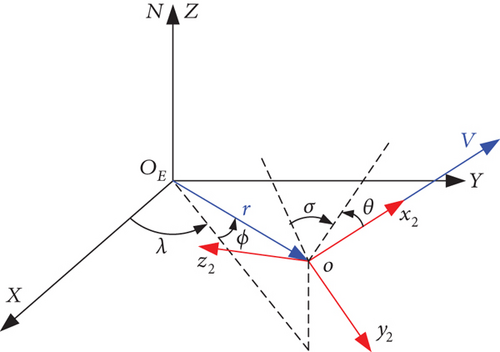
Since the descriptions of the state parameters such as the force, position, and velocity of an HGV are usually in different coordinate systems, the dynamic model is established in the flight path coordinate system o-x2y2z2 to ensure that analyses and calculations are conducted under the same space-time reference.
The earth-centered inertial coordinate system OE-XYZ is a geocentric coordinate system with its origin OE at the center of the earth. The OEX axis is the intersection of equatorial and ecliptic planes. The OEZ axis is the rotation direction of the earth. The OEY axis satisfies the right-hand rule. The origin o of the o-x2y2z2 coordinate system is the center of the vehicle mass. The ox2 axis is the direction of the flight velocity. The axis oy2 is located in the plane formed by the velocity vector and the vector from the center of the earth to the vehicle, perpendicular to the axis ox2, and positive in the upward direction. The oz2 axis satisfies the right-hand rule, as shown in Figure 1.
2.2. Dynamic Equations
2.3. Constraint Analysis
3. Multiple Leap Maneuver Flight Profile Design
In this paper, to achieve the goal of an active leap maneuver within the longitudinal flight profile during the gliding phase, the standard maneuver reference drag acceleration curve is designed in the drag acceleration-normalized energy ratio (D-e) profile. First, the gliding corridor is determined in the angle of attack α flight profile. Then, the reference standard maneuver drag acceleration is determined based on the analytic form of the single-parameter mapping of the range to go. Finally, the algorithm for updating and preprocessing the standard reference maneuver drag acceleration is provided.
3.1. Profile Design of the Angle of Attack α
3.2. Determination of the Gliding Flight Corridor
Dmax and Dmin represent the upper and lower boundaries of the D-e profile gliding corridor, respectively.
3.3. Drag Acceleration Profile Design of Multiple Leap Maneuver Mode
3.3.1. Reference Drag Acceleration Profile Planning Algorithm
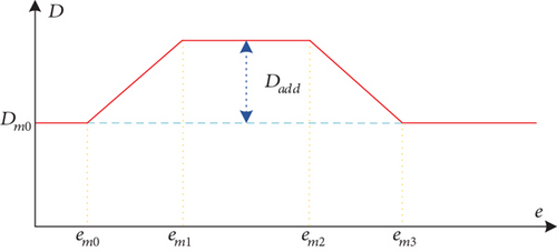
The preset maneuver corridor is [e1, e2], and the drag acceleration is taken as D2, which is the benchmark. The estimated range to go based on the single-stage maneuver drag acceleration mode is calculated as follows:
3.3.2. Reference Drag Acceleration Profile Update Algorithm
The updated reference drag acceleration profile maintains the form of Eq. (14).
3.3.3. Reference Drag Acceleration Profile Preprocessing Algorithm
Using a piecewise linear drag acceleration form, Eq. (14) may lead to first-order discontinuity in the design profile, which could lead to significant abrupt changes in the guidance command. Therefore, it is necessary to implement a smooth transition process near the segment endpoints or the profile design nodes to address this issue.
Eq. (24) ensures that the smooth transition trajectory does not exceed other design nodes and maintains the main characteristics of the broken line reference drag acceleration curve.
4. Maneuver Drag Acceleration Tracking Guidance Law
When the drag acceleration profile design is obtained, it is necessary to design the tracking guidance law to track the design profile. In this paper, the bank angle ν is chosen as the control variable to ensure that the actual drag acceleration D equals the corresponding standard reference drag acceleration of the profile. In this section, the method based on the sliding mode and preset performance control is used to design the standard reference drag acceleration tracking guidance law to ensure that the vehicle satisfies multiple constraints at the gliding terminal time.
It is proved in Reference [45] and Reference [46] that the conversion error function is uniformly bounded by the guidance law (Eq. (44)) under the condition that the interference error is bounded, the sliding mode surface s is guaranteed to be within the error envelope, and the tracking error e approaches zero.
5. Simulation Verification and Analysis
The guidance parameters are set to ke = 0.5, kz = 0.52, τf = 0.2, , , and kρ = 0.02. The constraints for the dynamic pressure, load factor, and heat flux during the gliding phase are qmax = 200 kPa, nmax = 3 g0, and , respectively. The target location is 115°E and 32°N.
5.1. Nominal Mission Simulation
To verify the effectiveness of the designed reference drag acceleration profile and the tracking guidance law under multiple active leap maneuver modes, two sets of different initial conditions are selected for simulation analysis in this section. The initial state and the terminal constraints of the gliding phase are shown in Tables 1 and 2, respectively.
| Mission | h0 (m) | λ0 (°) | ϕ0 (°) | V0 (m/s) | θ0 (°) | σ0 (°) |
|---|---|---|---|---|---|---|
| 1 | 39000 | 118 | 18 | 5440 | 0 | -10.4 |
| 2 | 41000 | 100 | 23 | 5120 | 0 | 52.6 |
| hf (m) | Stogo,f (m) | Vf (m/s) |
|---|---|---|
| 18000 | 20000 | 1280 |
Simulations were conducted using the drag acceleration profile design method and tracking guidance algorithm proposed in this article. The results are as follows. Figure 3 is the reference drag acceleration and actual drag acceleration curve under the two-stage longitudinal leap maneuver modes in the D-e profile. It can be seen from the figure that the turning point of the reference drag acceleration profile is smooth and the tracking error of the actual drag acceleration is very small. This indicates that the vehicle can effectively control drag acceleration and maintain a stable flight state during the gliding phase.
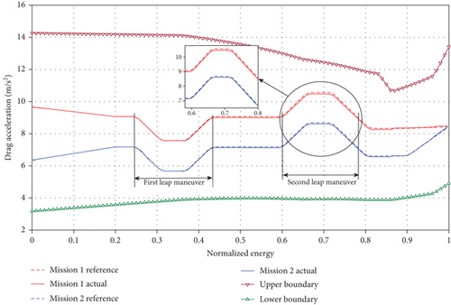
The variations in the vehicle angle of attack α and command bank angle ν are shown in Figures 4 and 5, respectively. Figures 6 and 7 present the three-dimensional trajectories and velocity-altitude curve during the gliding phase, respectively. It can be concluded that the algorithm studied in this paper can guide the vehicle to the terminal expected state and satisfy the multiple constraint conditions. The guidance algorithms exhibit strong adaptability. Further analysis reveals that the variation in the reference drag acceleration designed in Figure 3 can achieve the longitudinal leap maneuver shown in Figure 6. When the drag acceleration significantly changes, the high-precision tracking of the drag acceleration can be realized by implementing the rapid large-scale bank angle.
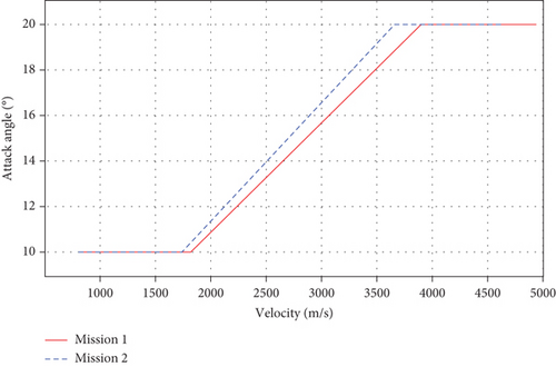
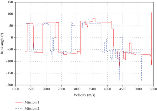
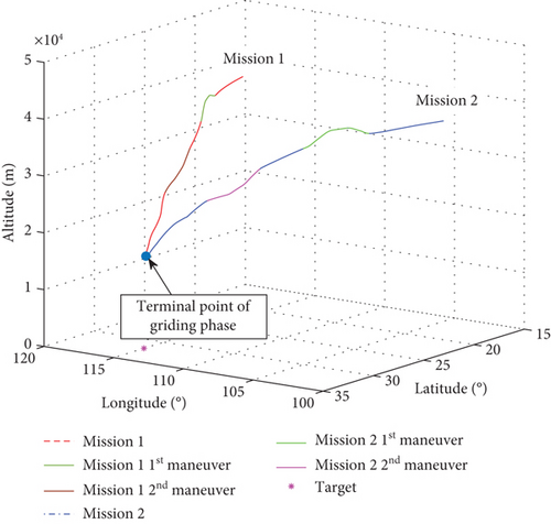
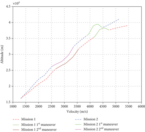
Table 3 shows the terminal actual state of the gliding phase. The terminal altitude error is less than 220 m, the terminal range to go error is less than 100 m, and the velocity error is less than 10 m/s, which can accurately satisfy the constraints of the gliding handover.
| Mission | hf (m) | Stogo,f (m) | Vf (m/s) |
|---|---|---|---|
| 1 | 18135 | 20040 | 1304 |
| 2 | 18217 | 20080 | 1308 |
5.2. Monte Carlo Simulation
To verify the robustness of the design method to the initial state deviation and aerodynamic parameter uncertainties, the Monte Carlo simulations are carried out. The initial state of the gliding phase simulation of the vehicle is based on the mission 1 state in Table 1, and the range of disturbance deviations is selected based on the 3σ principles, as shown in Table 4.
| h0 | V0 | θ0 | σ0 | CL | CD |
|---|---|---|---|---|---|
| ±2000 m | ±300 m/s | ±0.5° | ±10° | ±20% | ±20% |
The Monte Carlo simulation results of 200 dispersed cases are shown in Figures 8–11.
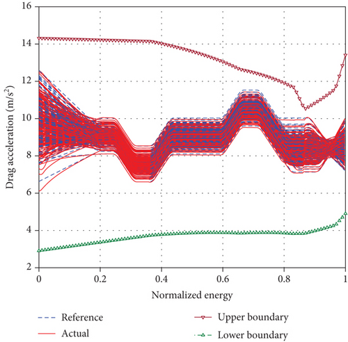
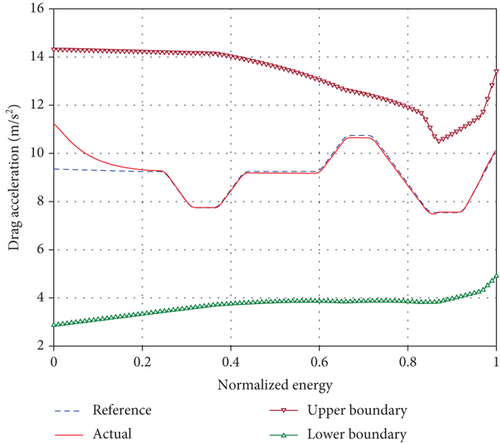
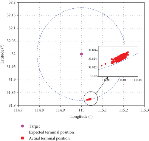
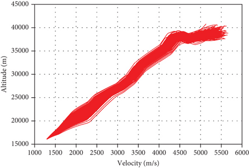
From the calculation results of Figures 8 and 9, it can be seen that due to the influence of aerodynamic parameter deviations, there is a certain deviation between the actual drag acceleration and the reference resistance acceleration in the initial stage of gliding. The gliding guidance law studied in this paper can quickly converge to the design profile of the reference drag acceleration in finite time and maintain high-precision tracking. The drag acceleration state of the reference terminal is corrected by the online estimation of the aerodynamic coefficient to ensure that the vehicle meets the terminal state handover constraint requirements. The terminal positions during the gliding phase under comprehensive deviation conditions are shown in Figure 10. The actual positions are all located on the circle that satisfies the remaining gliding terminal range constraints. The statistical simulation results show that the mean and variance of Stogo,f are 19986.8 m and 75.3 m, respectively, and the mean and variance of hf are 18032.4 m and 169.6 m, respectively. The Monte Carlo simulation results demonstrate that the design method of the drag acceleration profile and the gliding guidance algorithm for the multiple leap maneuver mode proposed in this paper are reliable and effective, with strong adaptability.
6. Conclusions
In this paper, a fast design algorithm of drag accelerations that can be used to achieve multiple maneuvers in the gliding phase and a gliding guidance algorithm with a strong anti-interference ability are proposed. Through single-parameter analytical iterations, the reference drag acceleration profile of multiple leap maneuvers satisfying process and terminal constraints can be quickly obtained, which has the potential for online planning applications. The drag acceleration tracking algorithm based on the sliding mode and prescribed performance control has a strong anti-interference ability. The simulation results show that the drag acceleration profile design method and tracking guidance algorithm in this paper have good adaptability and robustness based on different missions and disturbance deviation conditions and have great engineering application potential.
Conflicts of Interest
The authors declare that they have no conflicts of interest.
Acknowledgments
This study was funded by the National Natural Science Foundation of China (grant no.: 62101579).
Open Research
Data Availability
The data that support the findings of this study are available from the corresponding author upon reasonable request.


