A Review on Solid Oxide Fuel Cell Technology: An Efficient Energy Conversion System
Abstract
The increasing global dependence on fossil fuels for energy has prompted researchers to explore alternative power generation sources that offer higher efficiency, cost-effectiveness, and low environmental impact. Developed countries have been making continuous efforts to reduce their reliance on depleting fossil fuel sources to curb carbon emissions. As a result, hydrogen has gained significant attention among researchers as a potential future fuel that meets all the necessary criteria. Many countries aiming for a hydrogen economy have invested in research on fuel cells. Among various fuel cells, the solid oxide fuel cell (SOFC) has emerged as a commercially viable power source at a small scale. This paper provides an extensive review of the components, materials, design, operation, and integration strategies of SOFCs with existing thermal-based power plants. The performance and prospects of various SOFCs in standalone and hybrid modes are summarized, along with the limitations. Additionally, the research and commercialization efforts that can enhance the potential applications of SOFCs as a sustainable and reliable system in the long term are outlined.
1. Introduction
The exponential growth in population, urbanization, industrialization, and technological advancement, along with the current global standard of living, has led to a significant increase in energy consumption. For many decades, fossil fuels have accounted for 80% of the world’s energy demand. According to the World Energy Outlook report published by the International Energy Agency, the power sector alone consumed 20% of the total global energy for electricity generation, with 59% coming from coal, 24% from natural gas, and 4% from oil in 2021 [1]. The energy demand is projected to continue rising, with the forecast installed electricity generation capacity reaching 12,420 GW by 2040 [2]. However, the increasing reliance on fossil fuels for power consumption has had a severe impact on the environment and human health [3]. Issues such as global warming, climate change, and environmental pollution are accelerating due to the emission of greenhouse gases and other harmful substances. Given that the power sector is a major contributor to global greenhouse gas emissions and other harmful pollutants, there are growing concerns worldwide regarding the current trajectory of energy system development, sustainability, and the responsible use of energy resources. Achieving better performance in power systems necessitates proper system configuration, suitable materials, appropriate fuels, effective control strategies, and sound management practices. To ensure a sustainable future, tomorrow’s energy systems must prioritize high efficiency and environmental friendliness by embracing new, advanced, and clean technologies.
Standalone thermal power plants based on gas turbines and the Rankine cycle exhibit low thermal efficiency due to significant irreversibility in their operations. Substantial exergy losses occur in the combustion chamber of gas turbine power plants [4, 5]. In the case of steam turbine power plants, approximately 89% of the total exergy losses occur across the steam generator, turbine, and condenser [6]. The efficiency of heat engines is limited by Carnot’s efficiency, which is determined by the amount of heat that is rejected, as well as the presence of various dynamic components within the engine. Furthermore, in these power plants, the chemical energy of the fuel is first converted into thermal energy through a combustion reaction, resulting in the production of toxic emissions. The thermal energy is then transformed into mechanical energy.
In contrast, a fuel cell is a stationary device that directly converts the chemical energy of the fuel into electrical energy through a single-step electrochemical reaction. It operates similarly to a battery but without the need for recharging. Unlike heat engines, fuel cells are not subject to the limitations imposed by Carnot’s efficiency and emit minimal emissions. While heat engines cannot utilize all the energy they receive without rejecting some as heat exhaust, fuel cells cannot convert the entire Gibbs free energy generated by the electrochemical reaction into electricity without producing some heat. The exergy loss in fuel cells is primarily associated with the electrode reactions, and the efficiency of the cell can be improved by increasing system pressure and temperature [7]. A study analyzed that the maximum theoretical efficiency achievable for a methane-air fuel cell is 82.1%, and it can reach a 100% limit when the stoichiometric coefficient of air reaches 9.8 [8].
Sir William Grove first demonstrated the working of a fuel cell in 1842 by generating current between two platinum electrodes, with one end submerged in sulfuric acid and the other in a closed vessel filled with hydrogen and oxygen. In 1896, Wilhelm Borchers patented the first fuel cell that used carbon monoxide as the working fluid. Francis Bacon developed a practical fuel cell and, in 1959, introduced a 6-kW alkaline fuel cell with 60% efficiency [9]. Since then, several types of fuel cells have been developed, including alkaline fuel cells (AFC), polymer electrolyte membrane fuel cells (PEMFC), direct methanol fuel cells (DMFC), phosphoric acid fuel cells (PAFC) operating in the low-temperature range, and molten carbonate fuel cells (MCFC) and solid oxide fuel cells (SOFC) operating at high temperatures [10]. Table 1 presents the features of the four common types of fuel cells.
| Cell | Electrode and electrolyte | Electrical efficiency | CHP efficiency | Operating temp. | Application | Pros | Cons | Ref |
|---|---|---|---|---|---|---|---|---|
| PEM | Most electrolyte is a polymeric membrane, and the electrode material is porous carbon impregnated with a platinum catalyst | 36-38% |
|
Power source for stationary, portable, and transportation application | Less weight and volume | Efficiency decreases above 80°C. Prone to poisoning and costly | [11, 12] | |
| AFC | Aqueous potassium hydroxide soaked in a porous matrix or alkaline polymer membrane is used as an electrolyte | 60% | 80% | 40-75°C | Space application and transportation | Comparatively cheaper to fabricate and less sensitive to impurities and high efficiency | Susceptible to carbon dioxide poisoning | [13, 14] |
| PAFC | An electrolyte is a paper matrix soaked in phosphoric acid. The electrode used is gold, titanium, and tantalum | 37-42% | 85% | 150-200°C | Distributed generation | Tolerant to impurities, appropriate for CHP | Costly | [15, 16] |
| MCFC | A molten mixture of potassium and lithium carbonate. Thickest electrode electrolyte assembly | 45-50% | 80% | 650°C | Large utility application | Less sensitive to contaminants, appropriate for CHP and combined cycle | Low power density and prone to corrosion | [17] |
Among them, high-temperature fuel cells are suitable for electricity generation due to their hot reaction products, higher cell voltage, higher system efficiency, and fuel flexibility [18]. SOFC, first demonstrated by Bauer and Preis in 1937, has one of the highest electrical conversion efficiencies among all fuel cells [19]. Due to its elevated operating temperature, the hot exhaust gases released by SOFC contain significant available energy, making it suitable for large-scale power generation units and mini-cogeneration units [20]. SOFCs emit negligible emissions, with minimal traces of nitrogen oxides, carbon monoxide, hydrocarbons, and sulfur oxides [2]. Efforts are underway in the US, Japan, and Europe to lower the operating temperature of SOFCs to reduce material costs, improve reliability, enable faster startup and shutdown, and reduce polarization losses [19, 21]. Table 2 highlights the initiatives undertaken by the top four developed economies (USA, China, European Union, and Japan) to promote the hydrogen economy.
| Countries | Initiatives |
|---|---|
| Japan | In 2017, Japan became the first developed economy to adopt a hydrogen strategy. According to an IEA report from 2021, Japan plans to have eight hundred thousand fuel cell vehicles (FCV) and five million fuel cells for residences in order to meet carbon emission reduction targets in power, transportation and industry sector [22]. |
| China | A project of Center for Strategic and International Studies was published in 2022 that China leads the world in hydrogen generation and globally ranks third in fuel cell vehicle market with the aim to have 300 hydrogen refueling stations and one million FCVs by 2030 [23]. |
| EU | According to world economic forum data published in March 2023, EU leads the world in hydrogen energy patents during the period 2011-2020 and also in hydrogen storage. The EU has aimed to utilize 20 Mt of renewable hydrogen by 2030 [24]. |
| US | The USA is the second-largest consumer of hydrogen energy. According to the Fuel Cell and Hydrogen Energy Association of the USA, a roadmap has been developed in four steps towards a hydrogen economy, aiming to achieve a net-zero carbon economy and meet a projected net demand of 20 million metric tons of hydrogen by 2050. The first two phases of the roadmap prioritize research and development [25]. |
Numerous articles in the literature discuss various SOFC stacks, designs, component materials, fabrication techniques, performance evaluations, and potential applications [21, 26–28]. The design of an SOFC stack is primarily determined by its intended application, fuel type, and electrolyte material, with the electrolyte material exerting the most significant influence. In the literature, there are also discussions on different hybrid SOFC power-generating units [29–31], which will be further explored in Section 3. Various studies have utilized these models to conduct parametric sensitivity analysis, energy and exergy analysis, configuration analysis, optimization studies, feasibility studies, economic analysis, performance analysis under full and part load conditions, and steady-state and transient analysis. While numerous configurations have been proposed, a universally accepted design has yet to be established. Additionally, analysis results obtained through modeling approaches vary depending on the specific configuration and operating conditions. Researchers worldwide are actively developing advanced configurations for SOFC hybrid systems, aiming to expedite the transition to a hydrogen economy. In an effort to improve the use of SOFC either in standalone or hybrid mode, this review paper is aimed at presenting a comprehensive grasp of the component materials and design of SOFC as well as integration strategies. Additionally, the study outlines some technological limitations and details few of the small-scale commercial deployment of SOFC along with associated challenges in the end.
2. SOFC Technology
2.1. Function and Working of SOFC
A fuel cell is formed by the combination of an anode, cathode, and electrolyte. These individual cells are stacked together with bipolar plates in a fuel cell stack. The bipolar plates connect the anode of one cell to the cathode of the next cell in the stack assembly. This stack configuration is essential for generating current for various applications. In specific designs of solid oxide fuel cells (SOFCs), sealants are utilized to create a gas-tight seal, preventing gas leakage. For the fuel cell assembly to function properly, the electrodes (anode and cathode) must possess several crucial characteristics [32, 33].
2.1.1. Cathode
The cathode should be porous to enable the transfer of reactants and products to and from the reaction zone. It should also exhibit electrical conductivity higher than 10 S cm-1 and have sufficient electrocatalytic activity [34]. Additionally, the cathode material should possess chemical and mechanical stability, as well as high dimensional and morphological stability (without sintering). To avoid cracks and material breakdown, the cathode material should have compatible thermal expansion coefficients with other components (such as the electrolyte and interconnect) and possess adequate mechanical strength.
2.1.2. Anode
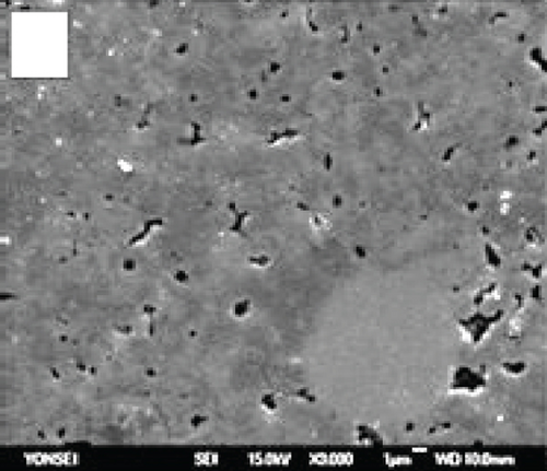
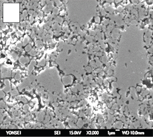
The anode in a fuel cell serves as the site for the fuel’s oxidation reaction, which can occur either internally within the cell or through an external source. The catalyst on the anode splits hydrogen into hydrogen protons and electrons. Figures 1(a) and 1(b) demonstrate the uniform distribution of pores across the grains of commonly used anode materials, such as nickel oxide-yttria-stabilized zirconia (NiO-YSZ) and nickel-yttria-stabilized zirconia (Ni-YSZ). Sufficient porosity enhances mass transfer and reduces voltage loss [35].
2.1.3. Interconnections
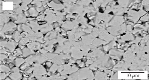
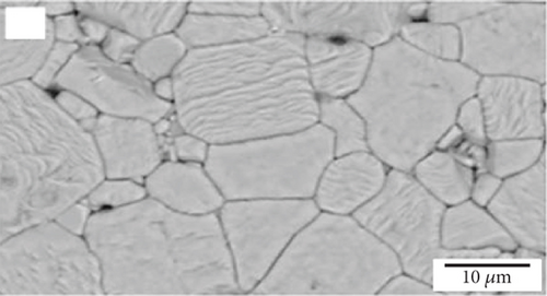
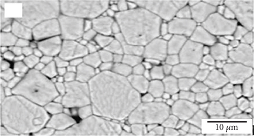
Interconnections in fuel cells should possess chemical stability, similar thermal expansion coefficients as other cell components, low material cost, and cost-effective fabrication methods. The protons and electrons produced at the anode pass through the electrolyte and combine with atmospheric oxygen on the cathode surface. Interconnecting plates facilitate the conduction of electrons between the electrodes, cells, and the external circuit; thus, they should have high electrical conductivity. Figure 2(a) illustrates the microstructure of a common interconnection material, lanthanum chromite (LaCrO3). Increasing calcium concentration in the material results in increased microstructure density, as seen in Figures 2(b) and 2(c) [36]. Since the interconnecting plates are in contact with both the anode and cathode, they must exhibit stability in both oxidizing and reducing atmospheres [37]. Chemical stability, similar thermal expansion coefficients as other cell components, low material cost, and cost-effective fabrication methods are also important requirements for interconnections in fuel cells.
2.1.4. Sealants
Sealants are used in fuel cells to prevent gas leakage from the inner portion of the cell to the outside and between different chambers. Leakage can occur due to the fracture of brittle materials under severe thermal stresses, cracking caused by mismatched coefficients of thermal expansion, and during thermal cycling of the components. Therefore, sealing materials must be of high quality. Tight sealing requires characteristics such as chemical compatibility and structural stability with the adjacent components within the fuel cell, improved adhesion, and limited thermal expansion on ceramic and metallic components [37, 38].
Materials for fuel cell components, such as the cathode, anode, electrolyte, bipolar plate, and sealants, must be selected based on various criteria, including resistivity, cost, thermal compatibility, and durability. Fuel cell components should exhibit low combined area-specific resistivity, which should not exceed 0.5 Ω cm. Area-specific resistivity is determined by the product of the component’s area and resistance. The choice of materials for fuel cell components is strongly influenced by the selection of the electrolyte, which has the greatest impact. The specific material selected will depend on factors such as the operating temperature range, intended application, and compatibility with other chosen materials. Detailed information regarding the materials used in manufacturing solid oxide fuel cell (SOFC) components, including various doping agents, can be found in Table 3.
| Electrolyte material characteristics | Limitations and alternatives |
|---|---|
| Bismuth oxide (δ-Bi2O3) electrolytes with fluorite structure operate in the intermediate temperature range remaining stable within 730°C-804°C with the highest conductivity at 804°C [39] | Reduces to bismuth at the anode, and mechanical strength is low. Doped Bi2O3 combined with ceria electrolyte or doping with ZrO2the decomposition can be prevented [40] |
| Crystalline-structured perovskite material lanthanum gallate (LaGaO3) is chemically stable with high ionic conductivity at a low-temperature range. When doped with strontium and magnesium to form LSGM, it demonstrates better conductivity and stability having similar thermal expansion coefficient as YSZ [40] | Gallium is reactive to nickel oxides contained in the NiO-LSGM-based anodes and has poor mechanical strength [39] |
| Yttria addition to zirconia to form YSZ has enhanced conductivity. Reacts with electrodes made from lanthanum-based perovskite oxide electrodes at high temperatures. Codoping alumina increases the mechanical property of YSZ. Scandia-doped zirconia has better conductivity compared to YSZ at lower temperatures but is scarce and expensive [41] | Aging of both YSZ and ScSz occurs during operational life. Increasing the percentage of Scandia and codoping indium oxide in ScSz mitigates the aging rate [42, 43] |
| Ceramic material ceria with fluorite structure has been doped with rare earth elements for better conductivity and compatibility at low temperatures | However, cell voltage drops under a reducing environment. Samarium-doped ceria (CSO) and gadolinium-doped ceria (CGO) exhibit better ionic conductivity at intermediate temperatures [39] |
|
— |
| Cathode material characteristics | Limitations and alternatives |
| Lanthanum strontium manganite (LSM) is a perovskite material for anode appropriate in high-temperature applications for its highly conductive and electrochemically active feature [47, 48] | Low temperatures lower the LSM performance while it is reactive towards yttria-stabilized zirconia at high temperatures. LSM can be covered with ceria doped with gadolinium (GDC) for high-temperature performance [49] |
| La0.58 Sr0.4 Fe0.8Co0.2 O3 (LSFC) perovskite material has good ionic conductivity | Chemically unstable with YSZ electrolyte. Infusing LNF and MgO into GDC-coated LSFC increases chemical stability and electrochemical performance [50] |
| SmBaCo2-xNixO5+δ(SBCNx) [51] and LBSCO-40GDC (LaBa0.5Sr0.5Co2 O5+δ) [52] are cobalt-based perovskite material suitable for cathode materials at intermediate temperatures | Cobalt has a high thermal coefficient and is expensive due to which these cobalt-based materials are incompatible with SOFC parts. NdBa0.5Sr0.5Cu2 O5+δ(NBSCO) [53] and NdBaFe2-xMnx O5+δ [54] are perovskite material free of cobalt element suitable for intermediate temperature SOFC operations |
| Anode material characteristics | Limitations and alternatives |
| Nickel material is a cheap and efficient electricity conductor. Combing with YSZ cermet to form Ni-YSZ ceramite acts as an excellent anode material for high-temperature applications | However, sulfur poisoning and coking when exposed to hydrocarbon are drawbacks for nickel-based materials. Alumina can also be added in appropriate proportions to improve stability, flexural strength and conductivity, and coking resistance [55]. The addition of silver also enhances conductivity and power density along with a reduction in carbon accumulation [56]. |
| Ceria can absorb sulfur, and Ni-SDC formed by doping nickel samaria with ceria can mitigate the impact of sulfur poisoning [57, 58] | For intermediate SOFC operation, mixing CaO and Cu to Ni-SDC further improves cell performance [59, 60] |
| Ti is chemically stable when exposed to a reducing environment. Nd0.5Sr0.5Ti0.5Mn0.5O3±d (NSTM) and SSTM are perovskite materials with enhanced conductivity at high temperatures suitable for high-range SOFC operations [61, 62]. Double perovskite material Sr2FeNb0.2Mo0.8O6-d (SFNM20) Pr0.5Ba0.5MnO3-d (PBMO3) and PrBaMn2O5þd (PBMO5) are some other nickel-free promising materials [63–65] |
2.2. SOFC Design
SOFC types can be classified based on their design and functioning [66]. In terms of design, SOFCs can be categorized into two sections: stack configuration and cell support. In terms of functioning, they can be classified into three sections: flow of reactants, operating temperature ranges, and charge carrier. The standard configurations of SOFCs include planar, tubular, and monolithic designs. These configurations can have either a single cell or multiple cells per stack. The bipolar plates can be made of either metallic or ceramic materials.
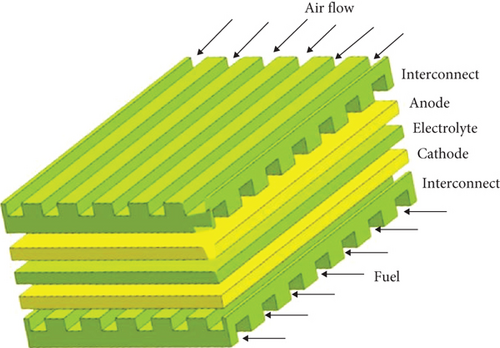
The planar type (see Figure 3) has a flat plate structure, with layers of cathode and anode separated by an electrolyte. For circular-shaped fuel cells, fuel is supplied through the center, while for square-shaped cells, fuel is supplied from the outer edges. Planar designs are relatively easier to fabricate and cost-effective. They offer lower ohmic resistance and higher overall power density. However, sealing can be more complex, increasing the risk of leakage and reducing thermal stress resistance.
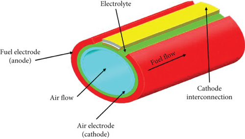
The tubular type (see Figure 4) consists of layers of anode, cathode, and electrolyte in the form of tubes. A tubular stack is formed by bundling several tubes together. In this design, the electrolyte and anode layer are rolled over the LSM tube, which acts as the cathode support [67]. Air is fed axially through the inner layer of the central cathode tube, while fuel is supplied to the outer layer of the anode. Unlike the planar design, a tubular cell does not require high-temperature sealants, providing better structural strength. However, the longer current flow path in tubular cells leads to lower power density and higher ohmic resistance [67]. The tubular design developed by Siemens-Westinghouse is considered the most advanced.
The monolithic design is a complex design that resembles a heat exchanger, with the air and fuel flowing either axially or perpendicularly to each other [68]. However, this design is associated with high costs and poor ionic conductivity [69].
Fuel cells can be classified based on support as either self-supporting or externally supported. In self-supporting fuel cells, one of the three fuel cell components serves as the thickest layer providing the support. Self-supported fuel cells can be further classified as anode-supported, cathode-supported, or electrolyte-supported. Electrolyte-supported cells have a thick electrolyte layer, which offers better mechanical strength but results in low conductivity due to strong ohmic resistance. To mitigate the ohmic losses, the operating temperatures of electrolyte-supported cells are increased, but this decrease the fuel cell lifetime. Electrode-supported cells have thin electrolyte layers, allowing for lower operating temperature ranges, but their mass flow is reduced due to thick electrodes. Anode-supported configurations exhibit high electrical conductivity, high heat transfer rates, and better structural stability. However, the anode-supported design may experience volume changes during oxidation and reoxidation cycles, which can affect its lifespan. In comparison, cathode-supported fuel cells have better lifespans due to the absence of a reoxidation cycle, but they come with higher manufacturing costs and reduced conductivity.
Externally supported fuel cells have an additional layer for support, which can be made of metal or substrate. This additional layer reduces the thickness of the fuel cell components in externally supported configurations. However, it increases design complexity to accommodate the extra layer. Metallic support configurations offer low operating temperatures and improved strength, but the base material remains susceptible to corrosion.
SOFCs can be classified into three categories based on their operating temperatures. SOFCs operating at temperatures above 850°C are categorized as high-temperature SOFCs (HT-SOFCs), those operating within the range of 650-850°C are considered intermediate-temperature SOFCs (IT-SOFCs), and those operating between 400 and 650°C are classified as low-temperature SOFCs (LT-SOFCs) [70]. Lower and medium operating temperatures increase the durability of the fuel cell and reduce the likelihood of sealant leakage but result in lower cell voltage.
Oxygen-conducting electrolytes have been more widely used in research and commercial applications, but proton-conducting electrolytes offer better ionic conductivity at lower temperature ranges, thereby reducing costs. Mixed ionic-electronic conductors have significant electronic conductivity, but this can lead to a decrease in cell voltage. Water is produced as a reaction product in oxygen-conducting SOFCs at the fuel electrode, in proton-conducting SOFCs at the air electrode, and in mixed ion-conducting SOFCs at both electrodes.
An electrolyte-free fuel cell refers to a configuration where the three layers of electrolyte and electrode within a fuel cell are combined into a single layer without any distinct interface between the electrode and electrolyte [71]. This concept was developed in 2010 and involves a single homogenous layer consisting of an oxygen ion conductor and semiconductor material [72]. The fabrication process is less complex, reducing manufacturing costs, and the absence of an interface helps to lower polarization losses.
SOFCs can also be classified based on their chamber design. The dual chamber arrangement involves fuel being admitted into the anode compartment and air into the cathode compartment. These separate compartments prevent direct contact between the fuel and air. Sealing is crucial in this design, and the thickness of the electrolyte layer is increased to prevent the transfer of reactants between the compartments. Both electrodes are exposed to the fuel and air mixture within the cell.
In contrast, a single-chamber configuration allows both the anode and cathode to be exposed to the fuel and air mixture. The anode only oxidizes the fuel and does not react with oxygen, while the cathode reduces oxygen but remains nonreactive towards the fuel. The absence of sealants in this design reduces material and fabrication complexity, resulting in lower manufacturing costs. However, the elevated operating temperature increases the risk of potential air-fuel explosions. A new configuration called the flat tubular SOFC (FT-SOFC) (refer to Figure 5) has been developed by combining the desirable design characteristics of tubular and planar cell structures. The anode support is in the form of a flattened tube that integrates cylindrical channels for fuel flow. This design remains cost-effective while offering improved power density and lower cell resistance [29, 73, 74].
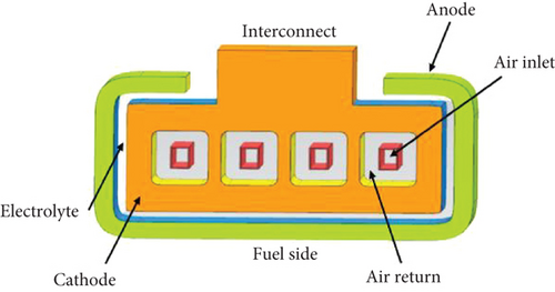
One of the major drawbacks of the HT-SOFC planar design is the issue of uneven thermal expansion within the layers. In comparison, the tubular design does not suffer from this problem as one end is free to expand, although it has a longer current path. To address this, an integrated planar solid oxide fuel cell (IP-SOFC) geometry design has been developed (refer to Figure 6) where one end is free to accommodate expansion, and the current path is reduced in length [73, 75]. Rolls Royce has created an experimental setup of an IP-SOFC fuel cell for research purposes [76].
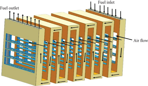
The basic unit of the IP-SOFC is a cell with an area of 540 mm2. Fifteen cells are printed on each side of a rectangular porous ceramic support, and they are connected in series through interconnections to form an IP tube. Ten of these planar tubes are connected in series next to each other to create a bundle. On each side of the planar tube, fifteen cells are connected in series, and the uncovered regions are coated with a glaze layer. Fuel is introduced at the tubes, where it flows upwards from the lower end in the first tube and downwards from the upper end to the adjacent tube. This repeated fuel flow pattern creates a serpentine path, and the current produced flows in the same direction. Air flows perpendicularly to the tubes through the cathodic channel space located between the tubes.
Microtubular SOFCs (MT-SOFCs) have gained significant interest among researchers since their introduction by Kendall in the 1990s [77]. As successors to large tubular SOFC cells, MT-SOFC tubes have a reduced outer diameter of less than 3 cm. This decrease in size results in a shorter current flow path, leading to a substantial increase in power density and improved thermal stability and mechanical strength. The rapid startup and shutdown capabilities and reduced weight make MT-SOFCs suitable for portable applications.
Various fabrication techniques, including classical extrusion, phase inversion, electrochemical deposition, gel casting, and dip coating methods, are used to manufacture MT-SOFCs [78]. Extrusion is the most commonly used technique for preparing MT-SOFCs. Using dip coating and extrusion methods, a 0.2 cm thick and 1.3 cm wide MT-SOFC has been successfully developed [79]. Extensive literature reviews have been conducted on the thermodynamic performance of MT-SOFC cells, stack design, and progress of MT-SOFC technology [80, 81].
2.3. Operation of SOFC
2.3.1. Fuel Processing
Methane is commonly used for direct and internal reforming processes, while higher hydrocarbon fuels like LPG, butane, propane, and diesel require external reforming. External reforming involves two separate sections, one for the steam reforming reaction and the other for the electrochemical reaction, which restricts direct heat exchange. In internal reforming, the heat needed for the endothermic reforming reactions is supplied from the electrochemical reactions occurring inside the cell. Internal reforming provides additional cooling for the SOFC stack as it utilizes the heat that would otherwise be wasted, increasing the temperature of the fuel cell stack. Internal reforming systems for SOFCs are relatively simple and efficient, eliminating the need for an external reformer and reducing plant costs [67, 73, 83].
Partial reforming is suitable for gases such as natural gas, landfill gas, and mine gas, where methane is the primary component. A reformer unit is used to partially reform methane into hydrogen. The output, which consists of a mixture of methane, hydrogen, and carbon monoxide, is then fed into the fuel cell unit. However, there can be a mismatch between the heat required for steam reforming and the heat available from the corresponding exothermic electrochemical reaction. This can result in local subcooling in the entrance region of the reformer, leading to uneven temperature distributions. Such temperature variations can increase the risk of mechanical failure in the SOFC due to induced thermal stresses [68].
Furthermore, at high temperatures, the cracking reaction causes carbon to accumulate on the anode section, leading to degradation of the fuel electrode material. This accumulation of carbon reduces cell performance and shortens the lifetime of the fuel cell. Therefore, in internal reforming operations, it is necessary to use anode materials with good catalytic properties for reforming and electrochemical reactions. An alternative approach to reforming is the direct oxidation reaction of hydrogen-based fuel within the fuel cell. However, this approach has the technical constraint of low power density and the risk of carbon deposition at the anode. To address these challenges, the concept of prereforming has been considered. Prereforming involves partially reforming the fuel in an external reformer, and the remaining reforming takes place internally within the fuel cell. This approach is aimed at mitigating the risks associated with carbon deposition while optimizing the overall fuel cell performance.
2.3.2. Basic Principle of Operation
Hydrogen and carbon monoxide generated from hydrocarbon reforming are supplied to the fuel electrode, while atmospheric oxygen is fed to the air electrode (refer to Figure 7). The surface of the air electrode acts as a catalyst for reduction reactions. Its porous structure enables the diffusion of oxygen gases, and at the interface of the air electrode and electrolyte, oxygen combines with electrons to generate oxygen ions. These oxygen ions can freely migrate through the electrolyte membrane due to its good ionic conductivity. On the other hand, the fuel electrode surface catalyzes the oxidation of hydrogen, carbon monoxide, and oxygen ions at the interface between the fuel electrode and electrolyte. This oxidation process produces water and carbon dioxide as products while liberating electrons. Due to the insulating property of the electrolyte, the electrons pass through a circuit, generating current in the process.

The porous structure of the fuel electrode facilitates the transfer of reactants to the anode-electrolyte interface and the removal of products away from the interface.
2.3.3. Electrochemical Reaction
Electrochemical reactions that occur at reactive sites of the anode and cathode of the SOFC are as follows:
Most fuel cells generate electrical power through the direct oxidation of H2, as shown in the exothermic electrochemical reaction mentioned above. However, under certain conditions, the anode of a solid oxide fuel cell (SOFC) may also support the direct electrochemical oxidation of CO and hydrocarbon fuels, typically at the entrance of the fuel cell [84]. The mechanisms for these processes are described as follows.
Reaction mechanism for CO is as follows:
Reaction mechanism for hydrocarbon fuel is as follows [85]:
3. SOFC-Integrated Systems
3.1. SOFC Integration Strategies
The high-temperature exhaust, consisting of unutilized hydrogen and carbon monoxide, released from standalone elevated temperature SOFC systems, contains significant available energy. Furthermore, due to the negligible contamination at elevated temperatures, a cheaper catalyst can be used instead of a noble catalyst. The utilization of the SOFC exhaust through hybrid modes, which has been an active area of research, is discussed in successive sections [86–97].
In a SOFC hybrid system, electricity is generated at all levels of the topping cycle and bottoming cycle, using either a single working fluid at the same pressure or dual fluids at different pressure levels. One common approach is to integrate a gas turbine cycle as a bottoming cycle to the SOFC. The exhaust stream generated within the SOFC is then combusted in the gas turbine for additional power generation [86–88]. The hybrid system, known as a solid oxide fuel cell-gas turbine system (SOFC-GT), can operate at either elevated pressure or atmospheric pressure. The pressurized SOFC-GT system, operating at high temperatures, has demonstrated superior performance due to enhanced cell voltage and better utilization of the SOFC exhaust [88]. On the other hand, an intermediate temperature SOFC-GT hybrid system is suitable for operation at atmospheric pressure. Even in this case, the exhaust stream from the gas turbine still contains significant available energy, which can be integrated into an additional bottoming cycle. The Cheng cycle has been proposed as a bottoming cycle to enhance the electrical efficiency of the SOFC-GT hybrid system [89]. Another alternative bottoming cycle is the Rankine cycle, which can utilize water and organic fluid to enhance the overall system efficiency [90–93].
In specific SOFC-GT systems, the exhaust from the gas turbine can exchange heat with the incoming fresh air of the SOFC through a heat exchanger. Additionally, in a SOFC combined heat and power (CHP) system, the exhaust gas stream from the SOFC is utilized to heat water via a heat exchanger for heating purposes [94, 95]. Some studies have also focused on integrating biomass with SOFC for fuel coupling [98–102].
3.2. Hybrid SOFC-Gas Turbine Systems
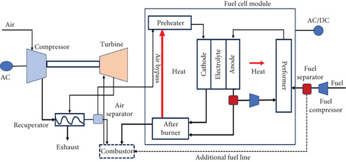
The combined SOFC-GT arrangement offers the flexibility to operate the SOFC at either atmospheric pressure or elevated pressure. In a pressurized system, compressed air at high pressure is directed to the cathode, while in a nonpressurized system, a mixture of atmospheric air and exhaust gas is supplied to the cathode. Pressurized SOFC-GT systems (refer to Figure 8) have been designed and utilized [88]. Despite the compactness and higher cell efficiency of the pressurized system, there are specific design and functional challenges that need to be addressed. These challenges include complexities in system layout, significant pressure differentials experienced by the anode and cathode, and the alignment of the SOFC and GT within the pressurized arrangement.
In an ambient pressure system, the GT pressure is not dependent on the cell pressure, allowing for a wide range of GT pressure options. The schematic of the ambient system is illustrated in Figure 9. On the other hand, in a pressurized system, higher power can be generated at elevated pressures due to the increased cell voltage, which rises with the GT pressure ratio. However, in an ambient pressure system, the GT pressure ratio does not affect the cell voltage, which remains constant.
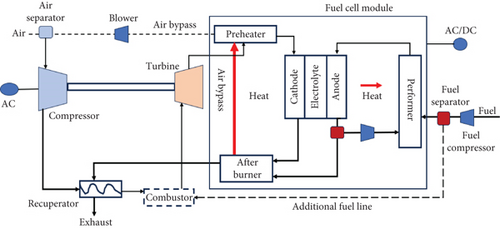
As a result, the pressurized system exhibits higher efficiency compared to the ambient system. This is due to the increase in turbine inlet temperature (TIT) and overall gas turbine power output with higher pressure levels. The ambient system may not be practical for high-pressure ratios as it would lead to lower turbine inlet temperature and efficiency compared to a standalone SOFC system [88]. Furthermore, the design options for the ambient system would be limited due to the constraints posed by the temperature of the recuperator.
The integration of SOFC into a GT power cycle can be achieved through either direct or indirect methods, as illustrated in Figures 10 and 11, respectively. In the direct SOFC-GT system, the fuel cell stack is positioned upstream of an afterburner. Any remaining fuel is burned, and the resulting gases are expanded in the gas turbine (GT). The inlet temperature of the GT can be increased by adding additional fuel to the afterburner in the direct SOFC-GT system.

In the indirect integration, the exhaust gases produced by the fuel cell are first passed through a heat exchanger, where they are heated. These hot gases are then directed to the combustion chamber of the GT cycle, where they preheat the air from the compressor. This indirect approach allows for the operation of the SOFC at atmospheric pressure, which reduces the sealing requirements. However, this configuration requires high temperatures and pressure differentials for the heat exchanger to efficiently transfer heat between the fuel cell and the GT cycle.
Both direct and indirect hybrid SOFC-GT systems exhibit higher efficiency compared to state-of-the-art recuperative GT systems. However, direct hybrid systems generally outperform indirect systems in terms of efficiency. The electrical efficiencies of indirect and direct hybrid SOFC-GT systems can reach 50-70% and above, respectively, even at low-pressure ratios, as mentioned in references [96, 97].
When considering efficiency and pressure ratio, the direct hybrid system initially experiences a rapid increase in efficiency, followed by an asymptotic pattern where efficiency becomes independent of the pressure ratio at higher pressures. On the other hand, the relationship between pressure ratio and efficiency in an indirect hybrid system resembles that of a conventional recuperative gas turbine arrangement. The efficiency initially increases with the rise in pressure ratio, reaching its highest value at a certain pressure ratio. Beyond this point, the efficiency of the indirect hybrid system decreases as the pressure ratio increases. Further discussion on this topic can be found in references [84, 97].
In a hybrid SOFC-GT configuration, the SOFC is typically responsible for generating the majority of power, while the GT contributes a relatively smaller portion to the total power output. According to reference [97], on average, the power output of the SOFC is three to five times greater than that of the gas turbine in both direct and indirect integration configurations.
3.3. Hybrid SOFC-Steam Turbine System
The solid oxide fuel cell-steam turbine (SOFC-ST) hybrid system is generally less complex compared to the SOFC-GT system, although it has a lower efficiency [92]. The SOFC-ST hybrid system is suitable for SOFCs that operate at intermediate and low temperatures [92]. Ongoing research is aimed at developing low-temperature SOFCs to reduce manufacturing costs, which would make the SOFC-ST hybrid system more effective than the SOFC-GT systems [92].
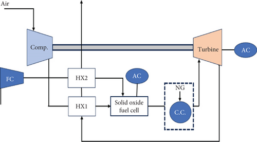
Figure 12 illustrates the schematic of a typical power cycle of an SOFC-ST system. In the hybrid SOFC-ST system, the heat from the exhaust stream of the SOFC and the afterburner is utilized to generate high-pressure steam in a heat recovery steam generator, which drives the bottoming cycle. In this specific diagram, the heated exhaust stream provides the heat required for preheating and reforming methane fuel into hydrogen, which then flows into the SOFC anode. The steam needed for fuel reforming is obtained by partially recycling the anode gas. Similarly, a portion of the depleted air from the SOFC cathode is recycled and mixed with the primary airflow to increase the temperature of the incoming air. By integrating the SOFC as a topping cycle with respect to the steam turbine cycle, the net efficiency of the hybrid cycle is increased compared to a standalone SOFC plant. Various alternative configurations for solid oxide fuel cell and gas turbine systems have been explored and discussed in published literature [89, 91, 93, 95]. In this setup, the SOFC contributes a higher power output, while the power generated by the bottoming steam turbine facility is relatively lower. This characteristic of the SOFC-ST arrangement is similar to the SOFC-GT hybrid system.

3.4. SOFC-Biomass Gasifier-Integrated System
Biomass is a plentiful renewable energy source available worldwide that can be utilized for various purposes. If biomass cultivation is done sustainably, the amount of carbon dioxide released during its operation is nearly equivalent to the amount absorbed through photosynthesis during plant life. Therefore, biomass utilization is highly promoted as it has a relatively low contribution to the increase of CO2 in the atmosphere. However, careful planning and responsible use of this resource are necessary to ensure the preservation of potential stocks for the future. In future energy systems, the key attributes for biomass conversion are adaptability and production efficiency.
The coexistence of biomass gasification and SOFC systems presents an encouraging and feasible prospect for the cogeneration of electricity and heat. Several research groups have examined and developed models for integrating SOFC and biomass gasification systems. Ahrenfeldt et al. [98] investigated the gasification of renewable resources for sustainable resource preservation. The introduction of this process has facilitated the efficient utilization of biomass on a small and medium scale. Panopoulos et al. [99] studied the combination of an all-thermal biomass steam gasification process with an SOFC to create a CHP (combined heat and power) system with a nominal output of less than 1 MW, operating at near-atmospheric pressure. Athanasiou et al. [100] studied the thermodynamic processes of integrating biomass gasification and SOFC to develop a higher-efficiency sustainable technology. In another paper, Panopoulos et al. [101] examined the combination of a near-atmospheric pressure solid oxide fuel cell (SOFC) with a novel all-thermal biomass gasification process, creating a combined heat and power (CHP) system with a nominal output range of less than MWe. Sucipta et al. [102] investigated the electrical generation efficiency of a hybrid system that combines biomass SOFC and MGT technologies under various fuel scenarios related to standard biomass gasification processes using air, oxygen, and steam.
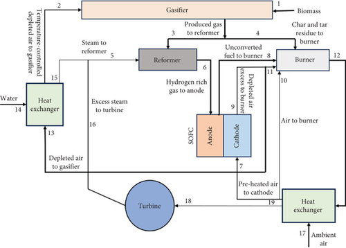
Figure 13 illustrates the integrated gasifier-SOFC process. This process includes a biogas reformer, gasifier, SOFC, burner for the complete combustion of solid residue and excess fuel, steam turbine, and required heat exchangers [100]. In a biomass SOFC-gasification (BG-SOFC) system, the producer gas from the gasifier (which contains hydrogen, methane, carbon monoxide, carbon dioxide, small amounts of tars below 1%, and steam) is fed into the SOFC. The hot effluent gases from the anode and cathode are then reinjected into the gasifier to maintain the reactor temperature, but at different gasification zones.
In addition to the aforementioned hybrid systems, several studies have investigated the integration of low-temperature PEM fuel cells with SOFCs [103–105] as a bottoming cycle, and the overall performance has demonstrated its viability for practical applications. Kim et al. [106] proposed a promising SOFC-PEMFC hybrid system with an organic Rankine cycle as the bottoming cycle, which generates electricity at all levels using pressure swing technology. With minimum mechanical components, the PEMC can reduce maintenance expenses. Wang et al. [107] proposed a diesel-powered SOFC-STIG hybrid model with a chemical looping hydrogen generation system that achieved an exergetic efficiency of 60%. Internal combustion engines connected with SOFCs for combined operation have shown improved efficiency and faster dynamic response compared to standalone engines [108, 109]. All the discussed hybrid systems depend on hydrogen generation systems that generate emissions. Hydrogen can be produced using electrochemical processes, such as the sulfur-iodine cycle seen in nuclear reactors operating at high temperatures [89]. This could lead to significant advancements in the study of SOFC hybrid cycles.
4. SOFC Limitations
As electrons move across the internal and external circuit of an SOFC, voltage losses occur due to irreversibility, resulting in a decrease in cell voltage. These losses are known as polarization or overpotentials and primarily originate from three sources: activation overpotential, ohmic overpotential, and concentration overpotential. The significance of each loss mechanism varies depending on the fuel cell type and its operating conditions. Migration of fuel and electrons through electrolytes can lead to voltage loss, which needs to be considered in the analysis [110–112].
Activation polarization arises from the energy threshold that the reacting species in a chemical reaction must overcome, known as activation energy [25]. The energy loss required to accelerate the overall electrochemical reaction is defined as activation loss, and it is caused by the sluggishness of reactions occurring on the electrode surface. Additional energy is needed to catalyze both the anode and cathode semireactions in order to expedite the overall electrochemical reaction [110]. Activation polarization results in a significant voltage drop in low- and medium-temperature SOFCs, but it becomes less significant at high temperatures [86]. Activation polarization occurs in both electrodes and is more pronounced at low current densities.
Ohmic overpotential occurs due to the hindrance of ionic flow in the ionic conductor (electrolyte) and the resistance to electron movement through the electronic conductors (anode, cathode, and interconnects). Minimizing ohmic polarization can be achieved by using a thin electrolyte, high-conductivity electrodes, suitable interconnect materials, and optimizing the SOFC design [85]. Concentration overpotential arises from the difference in fuel and oxygen concentrations at the anode and cathode compared to their bulk concentrations in the primary fuel and oxygen streams. This occurs when the electrochemical reaction rate exceeds the diffusion rate of reactants through the electrode [111]. Lowering the concentrations of reactant gases leads to reduced partial pressures and loss of electric potential, known as concentration overpotential. It is more significant when using impure reactant gases, such as hydrogen obtained from steam reforming [81]. However, at elevated operating temperatures, gas diffusion through the electrodes in SOFCs is highly efficient, resulting in minimal concentration losses unless fuel and air utilization rates are exceptionally high [85].
The deployment of SOFC and hybrid power plant projects by large industries and ongoing simulation work at research institutes highlight the technological complexities and advancements in SOFC and hybrid systems. Table 4 summarizes the constraints and initiatives aimed at overcoming these limitations.
| Constraints | Resolving initiatives |
|---|---|
| A common factor for loss in SOFC is degradation in which performance loss of electrolyte and electrodes can either be denoted by voltage loss per thousand hours or through change in area-specific resistivity. Degradation in electrolyte occurs due to poisoning, alteration in microstructure of material, and chemical and thermal stress [113]. In the case of electrodes, degradation is due to phase transformation, impurity, doping, and mechanical degradation due to chemical and thermal stresses [114]. | Current research has devised methods to retrieve back ASR after poisoning such as [115] has impregnated Ca element that increased current density and recovered ASR after degradation. |
| High-temperature operation of SOFC negatively impacts the fuel cell by shortening its lifetime and reducing its safety while raising the overall cost of electricity generation [116]. On the other hand, low temperature increases ohmic resistance and decreases power density. | Thin film electrolyte with refined microstructure offers shorter path for ion transfer, thereby reducing ohmic resistance. SOFCs with thin film electrolyte can operate at intermediate temperature without deteriorating performance and reduced operational cost [117, 118]. Another practical option is the proton-conducting ceramic fuel cell (PCFC), which is a SOFC that operates at low to intermediate temperatures [119]. |
| Difficulties arise during coupling SOFC fuel stack with gas turbine in the complex system configuration [120]. Continuous operation can also lead to sudden disruption of electricity generation. | Advanced control system and management strategies can be beneficial to optimize the hybrid system [109]. |
| Hybrid systems which are powered by fossil fuel still release carbon through exhaust stream contributing to greenhouse emissions. | Carbon released can be controlled through carbon capture technologies [121, 122]. |
| Majority of the expenditures associated with a SOFC system are related to the cost of the infrastructure, fuel, and equipment [120], thereby limiting its economic viability as power source. | Economies of scale, bulk production and longer lifetime of SOFC can compensate the high cost of SOFC deployment [123, 124]. |
5. SOFC Commercialization
Solid oxide fuel cells (SOFCs) have a wide range of applications, including portable power generators (250-500-watt battery chargers), small power systems (1-5 kW residential power and auxiliary power units used in automobiles, recreational vehicles, and heavy-duty trucks), and large-scale distributed generation power plants (e.g., 100-500 kW systems). Details about these system designs and concepts can be found in reference [125].
To achieve optimal efficiency, SOFCs are typically operated at fuel utilization rates of 80-95%. This results in the outlet gas stream from the SOFC stack containing valuable residual fuels. These residual fuels can be burned in an afterburner, and the resulting heat can be used for preheating air and fuel, as well as for external fuel reforming. Furthermore, the interplay of exothermic electrochemical and endothermic reforming reactions at elevated temperatures generates surplus thermal energy. SOFCs are well suited for combined heat and power (CHP) applications in hybrid mode.
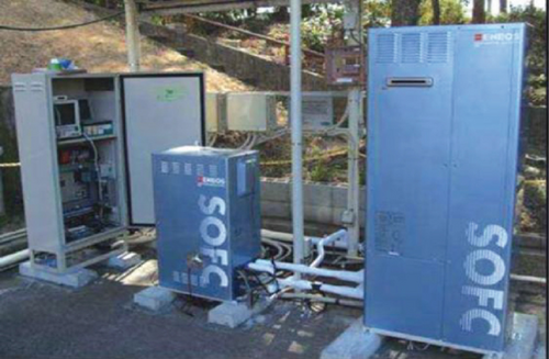
Sulzer Hexis of Switzerland has been developing planar SOFC systems in sizes ranging from 1 to 5 kW using improved sealing materials. In Japan, commercially used SOFC-based CHP systems of about 1 kW size provide electricity and hot water for residential applications (see Figure 14). Ceramic Fuel Cells Ltd. in Australia also produces similar CHP systems using SOFCs with yttria-stabilized zirconia (YSZ) electrolyte, operating at approximately 750-800°C. UK-based Ceres Power Ltd. develops wall-mountable residential CHP systems integrated with 1 kW size SOFCs using ceria-based electrolyte, which operate at relatively lower temperatures in the range of 550-600°C.
While the transportation sector can also utilize SOFCs, the most suitable option is typically the proton exchange membrane (PEM) fuel cell. However, PEM fuel cells require pure hydrogen, which is challenging and expensive to produce from gasoline and diesel due to technical complexities. In contrast, SOFCs can handle hydrogen fuel containing carbon monoxide (CO) and do not require noble metal catalysts, reducing the cell cost. Delphi Corporation is currently developing a 5 kW auxiliary power unit (APU) that utilizes anode-supported planar SOFCs and can run on gasoline or diesel reformed through partial catalytic oxidation. SOFC-integrated APUs are expected to be very useful for heavy-duty trucks, providing benefits such as reduced idling time, noise and emissions, and significant fuel savings.
In 2021, Bloom Energy, one of the pioneers in the field of SOFC technology, installed a 100 kW capacity SOFC powered by hydrogen in South Korea for electricity generation.
6. Research Challenges with SOFC
The research community faces significant challenges in SOFC design, including manufacturing cost, increased reliability, and reduction of polarization losses. The production of relevant components and the creation of ceramic formations are primary technical obstacles for SOFCs. The high operational temperatures of SOFCs require the use of expensive materials for the electrodes, electrolytes, interconnects, insulation, and seals. Achieving a suitable plant balance is also challenging due to the energy-intensive nature of operating SOFCs at high temperatures.
Research programs in Japan and the US are underway to develop thin film electrolytes using a simplified ceramic process. To be economically viable, an SOFC system must generate satisfactory power output at reduced operating temperatures. Operating SOFCs at lower or medium temperatures would significantly decrease startup periods, which are crucial for portable power applications. Utilizing thin oxide ion-conducting yttria-stabilized zirconia (YSZ) electrolytes or highly conducting electrolytes such as doped LaGaO3 can enable SOFCs to operate at lower temperatures [125]. The development of anode-supported cells using thin YSZ electrolyte (~10 μm) fabricated through tape calendaring and colloidal deposition techniques has made it possible to achieve SOFC operation at low temperatures with high power density [21].
However, the degradation mechanisms within the materials have not been thoroughly investigated due to technical constraints and their complex nature. The lack of guidelines for laboratory investigations on parameters such as current density and voltage impacts the accuracy of studies [126]. Recently, few more studies have been done on fuel cell technology in different fields of application to open the way for the researchers [127–130].
7. Conclusions
Fossil fuels are projected to remain the dominant source of energy for electricity generation in the near future, although renewable and nuclear energy sources are gradually increasing their share. However, emerging technologies like fuel cells, which are still in their early stages, have gained significant attention from researchers due to their potential for high-efficiency electricity generation. Solid oxide fuel cells (SOFCs), with their ability to utilize diverse fuels, achieve high system efficiency, produce negligible emissions, and integrate with existing technologies, show promising economic viability for commercialization.
Through the development of improved designs, new materials, and control systems, as well as the initiatives by countries to achieve carbon neutrality, the application of SOFCs may be further expanded to include vehicle and space applications. Currently, developed countries such as Japan, the US, and European nations are at the forefront of funding research and investments in SOFC technology. However, due to the complex operations and high cost associated with SOFCs, simulation remains the most popular research approach in this field.
Further research and development efforts will be crucial in overcoming the existing limitations of SOFC technology, which can significantly enhance its application in transportation and stationary power supply. Research in PCFC as a substitute to conventional SOFC is gaining momentum because of its innate ability to operate at lower temperatures with high efficiency and recycle any unused hydrogen. As countries strive for cleaner and more sustainable energy solutions, SOFCs have the potential to play a key role in achieving these goals.
Conflicts of Interest
The authors declare that they have no conflicts of interest.
Authors’ Contributions
Pranjal Sarmah was responsible for the idea for the article and draft. Amit Talukdar and Amrit Chakrovorty were responsible for the literature and data analysis. Prabhu Paramasivam, Virendra Kumar, Sathiyamoorthy, and Surendra Kumar Yadav revised the work.
Open Research
Data Availability
The data used to support the findings of this study are available from the corresponding author upon request.


