Topology Design of Modular Unit and Cable Network of On-Orbit Modular-Assembled Antenna
Abstract
With the increasing demands of ultra-large space antennas, on-orbit assembly stands out as a promising solution. However, this achievement necessitates the reconfiguration design of the whole antenna structure to maintain structural integrity and stability. In light of this challenge, a novel rapid design method is proposed for the unit configuration of modular-assembled antennas in this paper. The method utilizes an inscribed regular hexagon, which is positioned within a horizontal topological circle. The hexagon is subsequently projected onto a spinning paraboloid, resulting in the creation of unit nodes that conform to the shape of the paraboloid. The configuration of the unit topology is then determined based on the arrangement of these nodes. By using the method, two units of space-assembled antennas are designed. The topology design of the cable network is carried out for the modular unit. The pretensions of the cables are calculated. The results of the case study reveal that the developed modular units fulfill the requirements of the on-orbit-assembly antenna structure and can solve the engineering application difficulties of this type of antenna.
1. Introduction
With the continuous development of space technology and the increasing number of space activities, space structures are constantly developed in the direction of large scale and lightweight [1–4]. Large-scale space solar power stations of kilometer size, ultra-large space payloads, and ultra-large space science probes would play an increasingly important role in space activities such as the utilization of space resources, high-resolution earth observation, and exploration of the mysteries of the universe in the future. Constrained by launch size and weight, ultra-large space structures have to be constructed by on-orbit deployment and assembly.
The space on-orbit assembly technology has gradually changed from concept to reality since 1984. In 1985, the testing of the on-orbit assembly of the EASE/ACCESS truss structure was completed by NASA and ESA in the STS-61-B mission [5], which fully demonstrated the feasibility of the concept. After that, many on-orbit assemblies have been put forward by domestic and foreign scholars, most of which are in the phase of scheme research or experimental verification of key technologies [6–10].
In the design of on-orbit-assembled space structures, modularity and deployability are crucial. For space antennas, to assemble ultra-large structures effectively, it is essential to cleverly design modular trusses and cable network structures that can be efficiently assembled and deployed in orbit. ETS-VIII type modules have been extensively researched and applied [11–13]. Tian et al. conducted research on the hexagonal prism modular deployable antenna, which includes the topological design, the assembly of the modular units, and dynamics of hexagonal prism modules, and then developed a prototype to demonstrate the principles [14–19]. Wang et al. proposed a tension multilayer design method for the hexagonal prism modular deployable antenna, which improved the structural stiffness of the antenna [20]. Shi et al. designed a brand-new assembly interface for large space structures and analyzed its performance in detail according to the requirements of on-orbit assembly [21]. Dong et al. proposed a method for calculating assembly errors of assembly antennas considering assembly gaps [22]. Tang et al. analyzed the influences of systematic surface error by three factors including errors of faceted paraboloids, fabrication imperfections, and random thermal strains on orbit [23]. Fan et al. put forward a coordinate iteration algorithm for form-finding of cable network structure with equal tension; the uniformity of cable tension obtained by the algorithm is better than that by the minimum norm method or the equal force density method [24]. She et al. investigated the planning problem of the on-orbit assembling mission of a large space antenna structure [25]. Tibert presented a design method of a rigid prestressed tension truss antenna, which combines the basic rules of rigid truss structure with the effective form-finding method of cable network structure [26]. By establishing a structural mechanical model, Li et al. proposed a method of force-thermal matching design for cable network structures, which can improve surface accuracy to a certain extent in a temperature-varying environment [27].
In the aforementioned study, the modular antenna employed identical modules to approximate the parabolic surface, which proved to be challenging due to the inability to achieve precise fitting. Additionally, it is worth noticing that while the antenna employs modular units, it does not fall within the realm of on-orbit assembly. To meet the growing demand for ultra-large space antennas in space activities, it is necessary to conduct research on space antennas for on-orbit assembly, including the design of novel modules, precisely fitting antenna reflectors, and achieving the desired antenna size via on-orbit assembly.
In this paper, a configuration design method of a modular unit of large space-assembled antenna is proposed, which can generate configuration information of the modular unit efficiently, and solve the topology design problem of on-orbit-assembled antenna. Since the traditional division method of mesh surface has limitations in solving the cable relaxation problem in the proposed modular unit, a novel mesh surface topology is developed to solve the division problem of the cable network. This method effectively fills the challenging issue of mesh design for assembled antenna module units and avoids the cable relaxation problem caused by traditional mesh partitioning as well as develop hardware for a single module.
The rest of the paper is organized as follows. In Section 2, a fast configuration generation method of the modular unit is proposed for the modular-assembled antenna. In Section 3, a division method of cable network topology for modular units is proposed; the pretension design is carried out. Section 4 verifies the validity of the pretension calculation for the modular unit. Section 5 is a summary of the overall findings and conclusions.
2. Configuration Design of the Modular Units
The consensus among scholars suggests that on-orbit assembly is a viable and effective approach for constructing super-large space structures. It is also a necessary means to realize the super large size of the space structure. In order to obtain the parabolic reflective surface of the super-large on-orbit-antenna assembly, the design idea of modularity is adopted. Figure 1 shows the schematic diagram of an assembled paraboloidal antenna which consists of 19 modules. The antenna is constructed by hexagonal modules, which are composed of hexagonal trusses, tension cable networks, and metal reflective meshes, with different specifications.

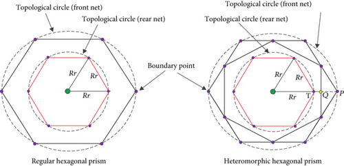
The configuration of the modular unit determines the reflecting surface and the assembling sequence of the on-orbit-assembled antenna. The paraboloidal antenna is constructed by utilizing the metal mesh of the module to conform to the shape of a paraboloid reflecting surface. To achieve optimal reflection performance of an antenna, all boundary points of the units must match the theoretical paraboloid. For maintaining the consistency of the assembly module units, all assembly units are projected on the horizontal plane inside a specified topological circle, and the assembly hexagon is designed to be an inscribed hexagon of the circle. As a result, a module unit structure design method based on topological circles is proposed.
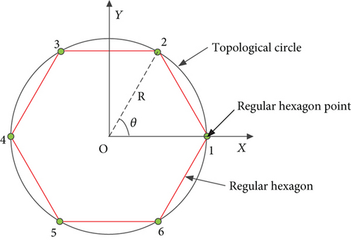
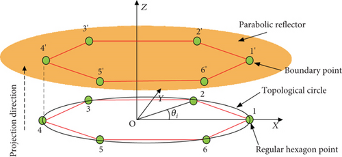
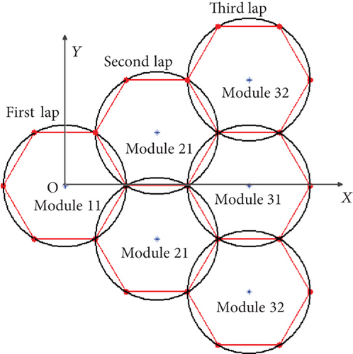
After calculating the location of boundary points, we proceed to determine the center of each topological circle for on-orbit assembly. Without loss of generality, the distribution of the 19 modular units of an assembled antenna is shown in Figure 3.
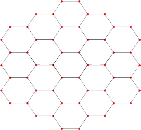
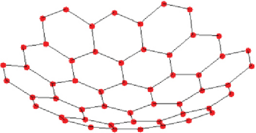
Since the assembled antenna is symmetrical about the centerline, one-sixth of the total modules is chosen to simplify the calculation. The selected modular units and the center of the corresponding topological circle are shown in Figure 4.
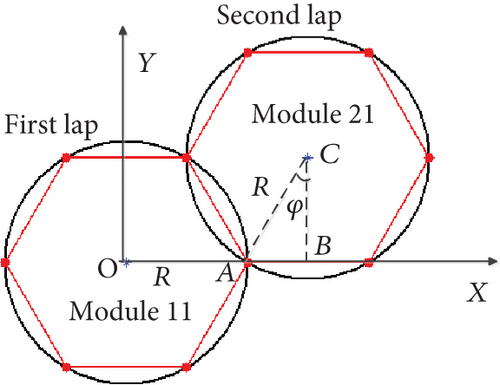
The calculated coordinates of the hexagonal units are adopted in the design of the modular unit. Each unit has two layers. It is required that all the vertices on the upper layer are located exactly at the obtained coordinates. Two modular units have been designed, as shown in Figures 5 and 6.


The module, which is shown in Figure 5, has the structure of a regular hexagonal prism with identical upper and lower layers. (xij, yij, zij) is the boundary node of the upper layer of the hexagonal prism, which can be solved by Equations (1)–(4). (xij, yij, z′ij) indicates the boundary nodes of the lower layer. The projection of the upper and lower surfaces along the axis of the prism coincides, that is, z′ij = zij − L, L is a given constant value.
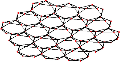
Once L is prescribed, the coordinates of all nodes on the lower layer of the heteromorphic hexagonal prism unit can be obtained from Equation (5). Figure 7 shows the topological structure of the assembly antenna constructed by the two proposed units.

3. Design of the Cable Network System
Currently, in the realm of on-orbit applications, large space mesh antennas utilize metal mesh as the primary medium for reflecting electromagnetic waves. The metal mesh is positioned atop the tension cable mesh, thus making the topological configuration of the tension cable mesh critical in determining the surface accuracy of the antenna. In the case of super-large on-orbit modular-assembled antennas, the modular units need to be folded during launching and deployed after entering orbit; the reflective surface of the modular unit adopts the cable network system. The conventional cable network is designed for structures with symmetry, whereas the modular units in the assembly antenna only have six boundary points, rendering them incapable of maintaining the balance required by the cable network. Consequently, the traditional cable network division is unsuitable for the two types of module units proposed in this paper, particularly the heteromorphic hexagonal prism unit. As a result, a novel cable network system has been developed in this section.
In Section 3.1, the cable network topologies are developed for the two units, respectively. In Section 3.2, the pretension of the proposed cable network is calculated.
3.1. Division of the Cable Network Topology
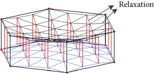
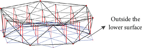
The regular hexagonal prism unit is comparable to the conventional loop antenna. The difference is mainly reflected in the considerably fewer boundary connection points the regular hexagonal assembly has than the loop antenna. The use of the three-dimensional grid, quasigeodesic grid, and other divisions cannot guarantee uniform stress on the cable network; cable relaxation might occur (Figure 8(a), [28]). Projections of the upper and lower surfaces of the heteromorphic hexagonal prism are misaligned, resulting in the fact that the symmetric triangle meshing cannot allow all networks to lie inside the lower surface of the unit, as shown in Figure 8. Therefore, a novel network topology scheme, which is adapted to the proposed units, is developed.
For properly tensioning the cables, the sag (δsag)is adopted in the network surface design [29]. Sag describes the sag of the edge cable, as shown in Figure 9.
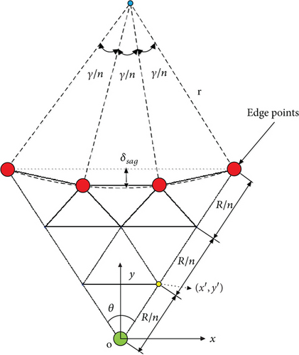
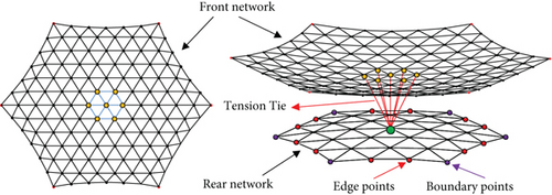
With the given δsag, the front network of the two module units has been designed as shown in Figure 10. First, the hexagons in the planar topological circle are meshed, where R is the radius of the topological circle and also the edge of the hexagon. The edges of the hexagon are then partitioned into n segments, where n ≥ 2. Subsequently, calculating the (x′, y′) coordinates of all triangle nodes is based on the geometric relationships with the given R and n. Then, substitute the edge points in Figure 10(a) with the calculated edge points that take into account δsag, as shown in Figure 10(b). Finally, by projecting all the triangular nodes inside the topological circle onto the parabolic surface, for instance , all the coordinates on the parabolic surface can be obtained as shown in Figure 10(c).

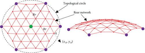
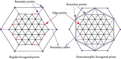
Considering the characteristics that regular triangles can form regular hexagons, a “many-to-one” cable network design method is proposed. The design procedure is shown in Figure 12.

- •
When the number of segments n = 2, no edge points exist in the rear network, and each rear network boundary point corresponds to three front nodes.
- •
When n = 3, there is no edge point in the rear network, and each rear network boundary point corresponds to six front nodes.
- •
When n is odd and n > 3, each rear network boundary point is associated with six front nodes, whereas each edge point is associated with seven front nodes.
- •
When n is even and n > 3, each rear network boundary point is associated with three front nodes, whereas the edge point is associated with five front nodes.
Figure 12(c) illustrates the distribution of the boundary cables of the rear network. In the case of regular hexagonal prisms, the rear network can be generated by connecting the boundary points of the rear network with the corresponding boundary points on the lower surface of the module unit. The rear network of the heteromorphic hexagonal prism units can be formed by connecting the boundary point and edge point of the rear network to the nearest boundary point on the bottom surface of the module unit. The comprehensive network design of the two prisms is shown in Figure 12(d).
The aforementioned design is capable of achieving the cable network topology configuration that meets the requirements of the assembled antenna module units. When all cables exhibit positive tension, it indicates that the entire cable network system is in a condition of pretension, hence preventing any relaxation.
3.2. Pretension of the Cable Network
The electrical performance of a large mesh antenna depends upon the specific geometry of its mesh reflector. The uniformity and stability of the mesh tension is the key to achieve the desired on-orbit profile. Hence, the form finding of the cable network is an essential step in designing the overall network structure. Applying a certain pretension on each cable is necessary to establish the position of each node within a theoretically stable configuration, while also ensuring a desired level of structural stiffness.
According to the optimization model of the force density in Equation (12), the pretension of cables of the above two units can be calculated, which is subsequently verified through Ansys analysis.
4. Case Studies
To support the validity of the proposed approach for generating modular unit meshes and to demonstrate its utility in practical engineering applications, a numerical example is performed. The specifications of the assembly antenna reflector are given as Table 1.
| Item | Aperture (mm) | Force length (mm) | Height (L ) (mm) | No. of modular units |
|---|---|---|---|---|
| Parameters | 200,000 | 80,000 | 1,000 | 7 |
The design of the two modular units and the cable networks is shown in Figure 13.


Utilizing the force density optimization method, the pretension of the two units is calculated. The results are presented in Tables 2 and 3, respectively. All cable tensions are positive, indicating that the cables are in a state of tension and not experiencing any relaxation or slackness.
| Item | Maximum | Minimum | Mean |
|---|---|---|---|
| Front net | 31.08 | 0.12 | 13.32 |
| Rear net | 61.97 | 13.86 | 24.51 |
| Tension tie | 2.83 | 0.44 | 1.85 |
| Item | Maximum | Minimum | Mean |
|---|---|---|---|
| Front net | 26.33 | 0.2 | 10.26 |
| Rear net | 74.29 | 1.9 | 26.29 |
| Tension tie | 2.36 | 0.26 | 1.36 |
The finite element model is established without including the truss element. The boundary nodes are fixed and constrained. The material parameters for the model are shown in Table 4.
| Item | Material | Diameter (mm) | Density (g/mm3) | Elastic modulus (GPa) | Poisson ratio |
|---|---|---|---|---|---|
| Cables | Carbon fiber | 1.4 | 1.8 × 10³ | 230 | 0.3 |
The finite element models and analysis results of the two modular units are shown in Figure 14.

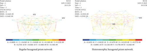
The finite element analysis adopts the static analysis in Ansys, and the link10 element is used to simulate the characteristics of the rope. The form of the internal stress of the rope tension analyzed above is assigned to the rope element. According to the result of finite element analysis, the deformations of the two types of cable networks are 0.164 × 10⁻⁹ and 0.293 × 10⁻⁹ m, respectively. Hence, the utilization of the initial force density method effectively addresses the tension in both types of modular units. This approach guarantees the uniform distribution of stress in cables, thereby maintaining the structural integrity and stability of the modular units. Furthermore, these advantages persist even under challenging environmental conditions in space.
Based on the proposed method for topology design of module unit, a prototype of the antenna assembly module was developed. The unfolded size of the prototype is 4.8 m, the folded size is 0.38 × 2.2 m, and the mass of a single module is 29.6 kg. The folding and unfolding function of the module is normal and consistent with the design, as shown in Figure 15.
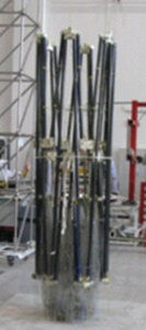
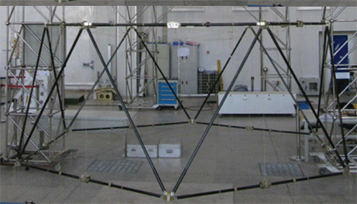
A module unit prototype for large space modular-assembled antennas has been developed. The prototype consists of a deployable module structure and a cable network system, and the successful development of the prototype proves the feasibility of the design method.
5. Conclusion
In this paper, the modular element design, mesh division, and mesh pretension computation of large space modular-assembled antenna are studied. A rapid design approach of modular unit configuration based on topological circles is proposed. The method enables the efficient generation of comprehensive module unit information of the whole assembled antenna. Furthermore, it facilitates the generation of all modules of the assembled antenna based on the predetermined unit information. A novel mesh division method is developed for the proposed unit structure. The network division approach effectively fulfills the requirements of prism units without the need for relaxation. The calculation of pretension is accomplished by using the force density optimization method. The finite element simulation provides empirical evidence that the proposed method ensures uniform and stable tension across the network.
Through an examination of the assembled antenna module units and module cable networks, this study confirms the effectiveness of the design strategy employed in the modular antenna system. The design approach successfully achieves the essential structural stability and stiffness necessary for on-orbit assembly, thereby establishing a solid basis for future engineering applications.
Conflicts of Interest
The authors declare no conflicts of interest.
Funding
This research has been supported by the National Natural Science Foundation of China (Grant Nos. 52222501 and 52192632).
Acknowledgments
This research has been supported by the National Natural Science Foundation of China (Grant Nos. 52222501 and 52192632).
Open Research
Data Availability Statement
The data that support the findings of this study are available on request from the corresponding author, Ma Xiaofei, upon reasonable request.


