Comprehensive Insight and Advancements in Material Design for Electrocatalytic Ammonia Production Technologies: An Alternative Clean Energy
Abstract
Ammonia (NH3) stands out as a promising green energy carrier in the context of the world’s future energy demands. The current ammonia production heavily relies on the energy-intensive Haber–Bosch (H–B) process, contributing significantly to worldwide energy consumption (1–2%) and escalating carbon dioxide emissions by 1.5%. In light of the environmental and economic concerns associated with the H–B process, alternative electrochemical reduction methods for nitrogen and its derivatives have emerged as viable paths toward green energy production. While substantial research progress has been made in recent years, the transition from laboratory-scale investigations to industrial or commercial applications has been hindered by low efficiency and selectivity in electrocatalytic systems. Establishing a cohesive strategy to advance electrocatalysts for nitrogen and its derivatives electroreduction is crucial. This study delves into a fundamental understanding of materials engineering and the modulation of electrocatalysts for ammonia production. Drawing on insights from various foundational research efforts, the aim is to provide guidance for future research directions based on fundamental principles. This exploration seeks to propel the development of electrocatalysts, addressing the current challenges and steering research toward efficient and selective electrochemical reduction processes for sustainable ammonia production.
1. Introduction
In the pursuit of cooperative and practical climate action to mitigate CO2 emissions, the world is encouraged to adopt green energy storage as a viable alternative. This choice addresses the carbon challenge not only effectively but also in an affordable manner [1, 2]. Green ammonia has the potential to emerge as a clean fuel option capable of generating electricity and powering transportation, among other applications [3]. Currently, global ammonia production stands at 180 million tons annually, with a market value of USD 70 billion, and the demand is projected to rise continually in the coming seasons [4, 5]. Ammonia plays a crucial role as a chemical component in various industries, serving as a feedstock, fertilizer in agriculture, carbon-free energy carrier, clean fuel for transportation and power generation, refrigerant fluid, complexing agent in mining and metal manufacturing, and a key ingredient in the synthetic textile industry, cosmetics, vitamins, and drugs [6–8]. It is the second most produced chemical and ranks among the largest chemical industries by volume.
At present, 90% of ammonia production utilizes the Haber–Bosch (H–B) process, which requires harsh synthetic conditions (operating temperature: 400–500°C, pressure: 10–30 MPa), resulting in high energy consumption or energy penalties (1–2% of total energy, 3–5% of global natural gas, and 2.5 EJ) [9–11]. Additionally, this process contributes significantly to large carbon footprints (1.5% of carbon footprints in all greenhouse gases, emitting 450 Mt of CO2 annually) [12–14]. The H–B process releases 1.9–9.3 tons of CO2 per ton of ammonia production [7, 15, 16]. In today’s world, there is a growing demand for the ammonia economy to be redesigned in a sustainable manner, reducing reliance on fossil fuels and transitioning to renewable energy sources (Figure 1). The energy-intensive Haber–Bosch (H–B) process can be replaced by alternative methods, such as electrocatalytic ammonia production systems. Ultimately, the efficient use of ammonia as a fuel in large-scale industrial, commercial, transportation, and urban energy utilities could represent a major breakthrough in addressing the climate crisis, given its status as a zero-carbon emission fuel (N2, H2O).
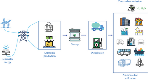
The journey toward industrial-scale synthesis of value-added ammonia through electrocatalytic processes is currently at a crossroads, facing significant hurdles. The pursuit of a highly efficient electrocatalyst presents formidable challenges encompassing ammonia yield rate, kinetics, selectivity, and stability [17]. Addressing this intricate landscape demands a meticulous approach to material design and engineering, with a focus on gaining a nuanced understanding of catalytic interactions involving reactants and intermediates on catalyst surfaces. This comprehensive review immerses itself in the vibrant realm of recent cutting-edge research dedicated to advancing electrocatalytic processes for ammonia synthesis. We embark on an exploration of materials engineering’s core, unraveling its profound influence on the behavior of reactants and intermediates. Through this analysis, we aim to not only assess the current landscape but also propose innovative directions for future research, shaping a strategic framework for materials development in this fascinating domain.
2. Ammonia as a Transformative Fuel for Sustainable Energy
Ammonia stands out as a promising fuel choice due to its high hydrogen content (17.6 wt%), impressive energy density (4.25 kWh L–1, 4.3 kWh kg–1), and convenient storage, transportation, and distribution within existing infrastructure [18, 19]. Positioned as an alternative carrier and supplier of hydrogen energy, ammonia finds direct applications as marine bunker fuel, fuel for heavy transport vehicles (adopted in Belgium since 1940), and across a spectrum of uses, including small-, medium-, and large-scale power generation, direct fuel cells, power turbines, and jet engines [12]. The combustion of ammonia in any of these devices produces only exhaust N2 and water, ensuring safe release into the environment at the point of use. Ammonia can be readily liquefied either by increasing the pressure to around 10 bar at room temperature or by cooling it to –33°C at atmospheric pressure (1 bar) [20]. Compared to hydrogen, ammonia exhibits a volumetric energy density three times higher and can be contained under modest pressure for transportation and storage (NH3 ~0.8 MPa vs. 17–69 MPa for H2). In terms of safety, ammonia surpasses other fuels like H2, propane, and gasoline in transportation. Ammonia boasts a high-octane number (130), and its high heat of vaporization (1371 kJ kg–1) helps extend torque capability and eliminate unwanted knocking [21, 22].
The physical properties of ammonia necessitate high-pressure storage vessels or refrigeration. Currently, ammonia storage is categorized as either large-scale or small-scale. Large-scale storage involves quantities of 50,000 tons stored in liquid form at –33°C at 1 bar, while small-scale storage maintains 1500 tons under the pressure of a steel sphere. Alternatively, ammonia can be stored in a semi-refrigerated state at intermediate temperatures and pressures. The most common forms of ammonia storage include anhydrous ammonia and aqua ammonia substances [23]. Anhydrous ammonia storage is prevalent in inorganic chemical applications, supplying fertilizers, polymers, DeNOx control, water treatment, and chemical processing. Ammonium hydroxide (aqua ammonia) is utilized in industrial cleaners, smelling salts, and glass cleaners. Due to safety concerns, meticulous attention must be given to ammonia storage. Ammonia leakage can lead to critical issues such as explosive reactions when mixed with air and severe health problems through inhalation, affecting organs and skin [24–26]. Ensuring rigorous safety measures and structural integrity is crucial for ammonia storage. Tanks must be well sealed to prevent potential bursting and reduce the risk of thermal expansions (ASME Boiler and Pressure Vessel Code, rated for 250 psig). While there are no published regulatory standards or specifications for aqua ammonia, it is recommended to adhere to standard practices similar to those applied to other constructed structures. Storage facilities should be equipped with fire-rated buildings, and a reliable leakage detection system, coupled with a timely response system, is essential for safeguarding the storage facility [26, 27]. Additionally, a safe alternative for ammonia storage is its solid form, achieved by binding it with metal salts to form metal amine complexes, such as Mg(NH3)6Cl2 and Ca(NH3)8Cl2 [28, 29]. This solid form of ammonia storage addresses the safety concerns associated with liquid amines and is considered the best alternative for mobile applications. Furthermore, the desorption of ammonia from these metal amines can be easily controlled, with the desorption temperature adjustable to suit specific application requirements [29, 30].
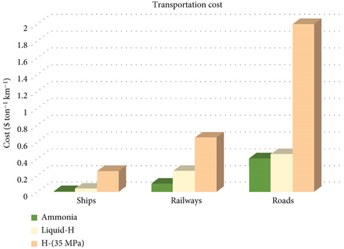
The even distribution of fuels from continent to continent, state to state, and within localized regions significantly impacts fuel economy. Transportation costs for fuels encompass factors like ensuring fuel integrity, logistics of transport, delivery, and storage. These elements play pivotal roles in assessing the broader feasibility and utilization of fuels from an economic perspective. In comparison between hydrogen and ammonia transportation, the ease and cost of ammonia transport are notably more favorable, positioning it as a more immediately feasible option (Figure 2). Consequently, these considerations suggest that the ammonia economy is more advanced and realistic than the hydrogen economy [21].
The production of green ammonia through electrolysis, plasma, and biological methods from renewable sources remains in the demonstration stage, primarily attributable to challenges associated with low conversion efficiency, faradic efficiency (around 5–20%), low current densities (1–20 mA s–1 cm–2), and limited scalability [7]. The high cost of renewable energy compared to fossil fuels stands out as a significant obstacle, impeding economic viability and hindering the widespread acceptance of ammonia as a clean energy source. The lack of economic feasibility sets the progress back and complicates the integration of ammonia into the energy landscape [12]. Achieving a successful transition to green ammonia requires collaborative efforts from various stakeholders, including governments, industries, researchers, and consumers. Coordination among these diverse entities is crucial for implementing effective and sustainable actions that can drive the development and adoption of green ammonia technologies by adopting innovation, investment, and policy support [3, 7].
3. Hydrogen Economy
Hydrogen stands out as a promising and sustainable energy carrier with the potential to replace the existing energy infrastructure, offering significant environmental, pollution, and health benefits. It can be produced from various sources, including water, biomass, and fossil fuels. In comparison to traditional fuels, hydrogen exhibits a higher gravimetric energy content (142 MJ kg–1) while maintaining a lower volumetric energy density (8 MJ L–1). For instance, gasoline has an energy content of 44 MJ kg–1 and 32 MJ L–1, respectively [31, 32].
Functioning as a clean and renewable fuel, hydrogen plays a crucial role in mitigating greenhouse gas emissions and addressing the impacts of climate change. It is adept at efficiently producing electricity with minimal waste, primarily water as a byproduct when burned in air. Hydrogen is versatile, powering transportation, buildings, and power generation. When utilized in fuel cells, hydrogen can reduce CO2 emissions by 20% if derived from conventional processes, achieving zero-emission status when produced from renewable sources [32, 33].
Hydrogen storage options include gaseous, liquid, and solid forms. Economically, the challenge lies more in the cost of hydrogen production than in utilization and storage costs. From a safety standpoint, hydrogen is nontoxic, and leakage poses no significant environmental threat. However, it is crucial to adhere to a strict concentration limit of 4% (vol/vol) to prevent serious fire and explosion risks. Ideally, concentrations should not exceed 1% (vol/vol) [34].
Hydrogen can be transported over long distances through pipelines and transmission lines using electricity. The Hydrogen Council’s 2020 prediction anticipates that hydrogen energy could fulfill 8% of global energy demand, with production costs reaching $2.5 per kilogram by 2030. By 2050, the estimated demand and supply for hydrogen are expected to reach 10 EJ per year, constituting 18% of the global demand [35].
Looking toward a green and economically viable future, hydrogen produced through electrolysis from renewable sources, combined with nitrogen from ambient air to produce green ammonia, presents a pragmatic energy utilization solution. Economically, hydrogen energy and the potential of ammonia as an ideal storage and carrier align favorably. Ammonia offers an alternative and more efficient transport process, enabling the transport of larger energy quantities over long distances with less spatial requirements. Notably, existing ammonia transportation facilities are already well established on a global scale [32].
4. Conventional Ammonia Generation Process
Fritz Haber, a German chemist and Nobel laureate in chemistry in 1918, collaborated with Carl Bosch at BASF in Ludwigshafen, Germany, to pioneer the heterogeneous catalytic H–B process (developing synthesis from hydrogen and nitrogen). This groundbreaking method was first employed on an industrial scale for ammonia production in 1913. Further development of the process to the high-pressure process earned Carl Bosch the Nobel Prize in Chemistry in 1931 [10]. In 2007, the German physicist Gerhard Ertl was honored with the Nobel Prize for his significant contributions to understanding and determining molecular mechanisms on surfaces, particularly in the catalytic synthesis of ammonia (H–B process) [36]. Today, century-old models continue to generate over 90% of the world’s ammonia. The significance of the Haber–Bosch process is underscored by its vital role in global food production; it is estimated that without this process, approximately 3 billion people would face starvation [37].
The H–B process is a method for producing ammonia from H2 and N2, driven by electricity (Figure 3). The H2 necessary for the process is obtained from the steam reforming of CH4 to H2, typically utilizing iron-based catalysts. This process operates under high-temperature conditions (400–500°C) and pressures (10–30 MPa), resulting in significant energy consumption (1–2% of total energy worldwide, equivalent to 2.5 EJ, and 3–5% of global natural gas) [15, 38–40]. The environmental impact is substantial, releasing 450 Mt of CO2 annually, contributing to a 1.5% carbon footprint in all greenhouse gas emissions [11, 41]. The H–B process is characterized by its large capital investment and a notable imbalance in regional distribution, with energy consumption totaling 5.5 EJ annually, approximately 38 GJ t–1 of NH3, and emitting 450 million tons of CO2. Notably, this process leads to CO2 emissions ranging from 1.9 to 9.3 tons per ton of NH3 produced [42].
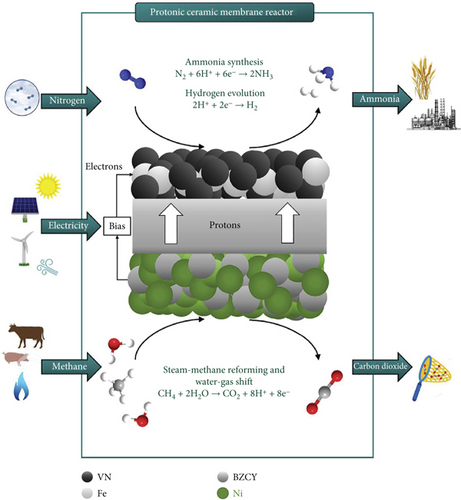
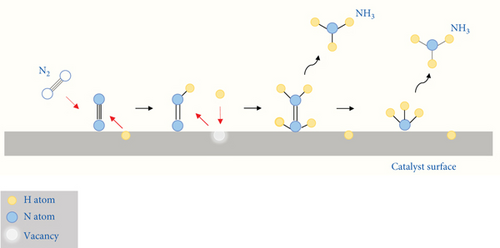
The H–B process evolves through the dissociative mechanism. The Fe-based catalyst, comprising 2 to 5 Fe atoms, interacts with N2 in a side-on mode, breaking the N≡N bond (941 kJ mol–1) into N adatoms. In the dissociative mechanism, the N≡N bond is initially broken before hydrogenation, leaving individual nitrogen adatoms on the catalyst surface, which is then independently converted into ammonia [44]. Simultaneously, H–H bonds in H2 rupture on the catalyst surface, reacting with N adatoms to form NH3. Directly breaking the N≡N bond requires large amounts of energy. The overall conversion of N2 and H2 to NH3 is 97%. This complex process consists of several steps, making it quite challenging: (a) catalytic steam reforming of CH4 to CO and H2, (b) water gas shift to produce more H2 from CO and convert CO into CO2, (c) removal of CO2 by absorption or adsorption, (d) catalytic CH4 formation to eliminate CO and CO2 from the H2, (e) purification of H2 and N2, (f) energy-intensive catalytic H–B process for ammonia production, and (g) purification of ammonia from unreacted H2 and N2 by refrigeration [45–47]. Annually, 60 million tons of H2 are produced for industrial purposes, with 95% coming from fossil fuels (gas, oil, and coal) and the remaining 5% from H2O electrolysis. Notably, 50% of the produced H2 is utilized to feed the H–B process for ammonia production [22, 43].
5. Electrochemical or Electrocatalytic Process
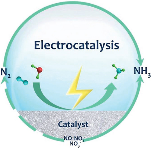
It is crucial to explore alternative approaches to ammonia production, addressing the energy-intensive H–B process. Various options, including biocatalysis, electrocatalysis, chemical looping, organometallic processes, biomimetic methods, photocatalysis, photo-electrochemical techniques, and plasma catalysis, are under consideration. Electrocatalysis is specifically examined, taking into account key factors such as the following: (a) utilizing renewable energy sources (solar, wind, and hydro) to drive the electrocatalytic process, (b) eliminating dependency on fossil fuels for H2 production, (c) scalability, (d) on-site demand design strategy, (e) eliminate byproducts and CO2 emissions, (f) achieving higher energy efficiency compared to H–B (40%), and (g) adopting an ambient condition approach [45, 46, 48–51]. Annually, human activities introduce 150 million metric tons of nitrogen into the environment, resulting in undesirable nitrogenous pollutants like reactive nitrogen compounds (, , NO2, N2O, NO, etc.) [52, 53]. Leveraging electrocatalytic processes offers a potential solution by reducing these pollutants to valuable products such as ammonia, mitigating environmental threats (Figure 4) [54].
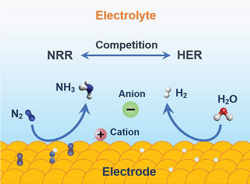
5.1. Nitrogen Reduction Reaction (NRR)
An electrochemical approach to synthesizing ammonia through nitrogen reduction reactions offers the advantages of mild operating conditions, zero CO2 emissions, and the ability to store electricity in chemical bonds. Scaling up this electrochemical process for industrial applications necessitates achieving a faradaic efficiency of over 50% and reaction rates of at least 10–7 mol s–1 cm–2. The nitrogen reduction reaction (NRR) is a challenging process due to (1) the high bonding energy of N≡N (941 kJ mol–1), making it difficult to rupture the bond, (2) a large energy gap (10.8 eV), (3) a high ionization potential (15.8 eV), (4) a negative electron affinity (–1.9 eV), (5) ultralow solubility (6.8 × 10⁻⁴ M, 1.01 × 10⁵ Pa, 25°C), and (6) the competition between NRR and HER [55]. The NRR is a multistep process that involves six electrons and six protons, suffering from sluggish kinetics. In contrast, the hydrogen evolution reaction (HER) is a two-electron process and is more kinetically preferred (equations (1)–((4)) [55, 57, 58].
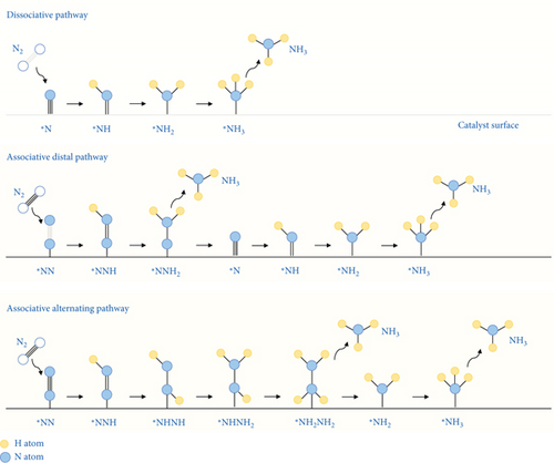
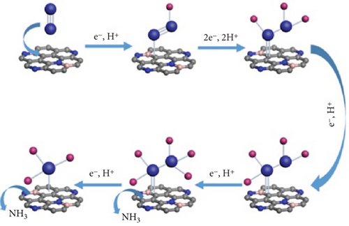
The electrochemical catalytic process of the nitrogen reduction reaction (NRR) does not favor the direct breaking of the N≡N bond. The NRR process involves the following steps: (1) adsorption of N2 molecules onto the catalyst surfaces, (2) the dissociative or associative breaking of the N≡N bond through hydrogenation, and (3) desorption of the generated ammonia. In the associative mechanism, the N≡N bond gradually breaks as the hydrogenation of nitrogen proceeds, ultimately releasing an NH3 molecule. The associative mechanism can be further categorized into (1) distal, (2) alternating (monoadsorbed), and (3) enzymatic pathways (dual-adsorbed) (Figures 5 and 6) [59].
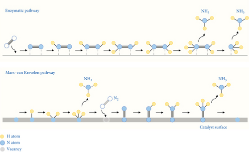
Transition metal nitride offers advantages over pure transition metal because the nitrogen atoms in the first surface layer are directly converted to ammonia. In the Mars–Van Krevelen (MvK) mechanism, lattice nitrogen is consumed, leading to the subsequent production of ammonia and the formation of surface nitrogen vacancies (Figure 6) [60]. The MvK mechanism demonstrates significantly lower activation energy requirements for ammonia synthesis, providing a highly kinetically accessible process with initial activation steps requiring lower energy. Nitrogen vacancies are replenished through the activation of N2 molecules, facilitating the progression to catalytic activity [61, 62].
5.1.1. Strategical Material Design for NRR
Strategically, precise control and design of materials for noble metal catalysts, such as Ag, Au, Pt, Ru, Rh, Pd, Os, and Ir, involve high atomic utilization processes through single-atom, nanostructure, and alloy formation for the NRR catalytic process. The high cost of noble metals strongly encourages the utilization of non-noble metal catalysts, including Fe, Ni, Bi, Co, Mo, Ti, and V (metal nitrides, sulfides, and oxides) [56, 63, 64]. The precise catalytic activity and selectivity of NRR could be improved through controlled approaches: (1) tuning the local reaction environment and (2) employing specific catalyst design strategies (vacancies, element doping, and construction of heterojunctions) (Table 1) [65–67].
| Materials | NH3 formation | FE (%) | Ref |
|---|---|---|---|
| NRR (nitrogen reduction reaction) | |||
| Fe on C nanotube | 2.2 × 10⁻³ gNH3 m–2 h–1 | 0.15 (–1.0 V)± | [40] |
| P nanosheet | 33.3 μg h–1 mgcat–1 | 5.0 (–0.6 V)± | [71] |
| PdCu | 35.7 μg h–1 mgcat–1 | 11.5 (–0.1 V) ∗ | [81] |
| Graphdiyne/Co2N | 219.7 μg h–1 mgcat–1 | 58.6 (–0.1 V) ∗ | [95] |
| Strained-TiO2 | 16.7 μg h–1 mgcat–1 | 26 (–0.5 V) ∗ | [98] |
| P-doped LDH on C nanofibers | 1.7 × 10⁻¹⁰ mol s–1 cm–2 | 23 (–0.5 V) ∗ | [48] |
| Nanoporous PdH | 20.4 μg h–1 mgcat–1 | 43.6 (–0.15 V) ∗ | [103] |
| Fe-(O-C2)4 | 32.1 μg h–1 mgcat–1 | 29.3 (–0.1 V) ∗ | [258] |
| Ni3B@NiB2.74 | 198.3 μmol h–1 cm–2 | 100 (–0.3 V) ∗ | [221] |
| Fe1Sx@TiO2 | 18.3 μg h–1 mgcat–1 | 17.3 (–0.2 V) ∗ | [58] |
| Co–Mo–CNF (C nanofiber) | 72.7 μg h–1 mgcat–1 | 34.5 (–0.5 V) ∗ | [57] |
| Boron carbon nitride | 20.9 μg h–1 mgcat–1 | 18.9 (–0.1 V) ∗ | [118] |
| Nickel-thiolate cluster (Ni6(PET)12) | 16.2 μg h–1 mgcat–1 | 25 (–1.8 V) ∗ | [47] |
| Fe3C/Fe3O4@C | 25.7 μg h–1 mgcat–1 | 22.5 (–0.2 V) ∗ | [94] |
| CoVP@NiFeV-LDHs | 1.6 × 10⁻⁶ mol h–1 cm–2 | 13.8 (–0.3 V) ∗ | [140] |
| N, B codoping porous C | 16 μg h–1 mgcat–1 | 10 (–0.2 V) ∗ | [141] |
| CoFe2O4 nanocube | 30.9 μg h–1 mgcat–1 | 11.6 (–0.4 V) ∗ | [142] |
| MoS2-x | 17.5 μg h–1 mgcat–1 | 24 (–0.2 V) ∗ | [113] |
| Rh anchored on CNT | 26.9 μg h–1 mgcat–1 | 15 (–0.1 V) ∗ | [259] |
| SV-1 T-MoS2@MoO3 | 116.1 μg h–1 mgcat–1 | 18.9 (–0.2 V) ∗ | [114] |
| Au@MOF | 49.5 μg h–1 mgcat–1 | 60.9 (–0.3 V) ∗ | [145] |
| O-CoP/CNT | 39.5 μg h–1 mgcat–1 | 19.4 (–0.5 V) ∗ | [115] |
| OVs-Pd3Pb-2 | 88.3 μg h–1 mgcat–1 | 41.1 (–0.05 V) ∗ | [260] |
| Cu2-xS/MoS2 quantum dot | 22.1 μg h–1 mgcat–1 | 6 (–0.5 V) ∗ | [86] |
| Au3Rh film on Ni foam | 26.2 μg h–1 mgcat–1 | 23.8 (–0.1 V) ∗ | [261] |
| PdH0.43 | 17.5 mg h–1 mgcat–1 | 18.5 (–0.2 V) ∗ | [104] |
| NiPS3 nanosheet | 118 μg h–1 mgcat–1 | 17 (–0.4 V) ∗ | [262] |
| B-doped nanoporous Pd film is directly formed on Ni foam | 29.0 μg h–1 mgcat–1 | 17.9 (–0.1 V) ∗ | [102] |
| P-doped N vacancy C3N4 | 28.6 μg h–1 mgcat–1 | 22.1 (–0.3 V) ∗ | [147] |
| CoFeB@ rGO nanostructures | 35.0 μg h–1 mgcat–1 | 31.6 (–0.2 V) ∗ | [148] |
| Mo-doped WO3@CdS | 38.9 μg h–1 mgcat–1 | 36.7 (–0.3 V) ∗ | [149] |
| MoSe2@g-CN | 7.7 μmol h–1 cm–2 | 28.9 (–0.3 V) ∗ | [150] |
| TiN/Pt-C3N4 | 105 μg h–1 mgcat–1 | — | [41] |
| C18-thiol-modified Fe-MoSe2 nanosheets | 34.8 μg h–1 mgcat–1 | 23.3 (–0.3 V) ∗ | [37] |
| Mn3O4 nanocubes | 11.6 μg h–1 mgcat–1 | 3.0 (–0.8 V) ∗ | [119] |
| Co-FePS3 | 90.6 μg h–1 mgcat–1 | 3.4 (–0.4 V) ∗ | [120] |
| Pt-WO3 | 342.4 μg h–1 mgcat–1 | 31.1 (–0.2 V) ∗ | [124] |
| Au25-Cys-Mo | 34.5 μg h–1 mgcat–1 | 26.5 (–0.2 V) ∗ | [128] |
| Cu-[OX]-Ce | 6.3 × 10⁻³ μg s–1 cm–2 | 18.2 (–0.3 V) ∗ | [135] |
| 2%Cu-OV-TiO2 | 13.6 μg h–1 mgcat–1 | 17.4 (–0.4 V) ∗ | [263] |
| C2N C | 5.9 μg h–1 mgcat–1 | 11.4 (–0.6 V) ∗ | [264] |
| LaFeO-Ru | 137.5 μg h–1 mgcat–1 | 56.9 (–0.7 V) ∗ | [138] |
| Cu–N/B–N | 146.2 μg h–1 mgcat–1 | 42.5 (–0.3 V) ∗ | [136] |
| Cu SAs/TiO2 | 6.3 μg h–1 mgcat–1 | 12.8 (–0.05 V) ∗ | [265] |
| Boron carbide nanosheets | 26.5 μg h–1 mgcat–1 | 15.9 (–0.75 V) ∗ | [19] |
| Ag nanodots on Ti mesh | 600.4 μg h–1 mgcat–1 | 10.1 (–0.25 V) ∗ | [17] |
| TiO2/Fe3O4 | 2.5 μmol 5 min–1 gcat–1 | — | [14] |
| Zerovalent Mo atoms on graphdiyne (Mo0/GDY) | 150 μg h–1 mgcat–1 | 16.0 (–0.1 V)˦ | [266] |
| Co-doped MoS2–x | 0.6 mmol h–1 gcat–1 | 10.0 (0.3 V)± | [88] |
| Fe−N4−C COFb | 33.6 μg h–1 mgcat–1 | 31.9 (–0.1 V) ∗ | [267] |
| Fe2Mo6S8 | Rapid NRR rates (>6 μg h−1 cm−2) | — | [11] |
| SiFe3W9 | 1.15 nmol sec–1 cm–2 | 25.0 (–0.1 V)ǐ | [38] |
| Ru single atoms anchored on graphdiyne/graphene sandwich structures | 56.8 μg h–1 mgcat–1 | 37.6 (–0.1 V) ∗ | [139] |
| TiO2/Ti3C2Tx | 32.1 μg h–1 mgcat–1 | 16.1 (–0.45 V) ∗ | [268] |
| TiO2 nanosheets | 35.6 μg h–1 mgcat–1 | 5.3 (–0.8 V) ∗ | [63] |
| F-doped C | 197.7 μg h–1 mgcat–1 | 54.8 (–0.3 V) ∗ | [269] |
| Se vacancies in MoSe2 | 3.04 × 10⁻¹⁰ mol s–1 cm–2 | 21.6 (–0.45 V) ∗ | [270] |
| NORR (nitrite reduction reaction) | |||
| Cu foam electrode | 517.7 μmol h–1 cm–2 | 93.5 (–1.8 V) ∗ | [170] |
| Pd/CuO nano-olives | 906.4 μg h–1 mgcat–1 | 91.8 (–1.5 V) ∗ | [271] |
| S-Co3O4 | 314.5 mmol h–1 gcat–1 | 87.6 (–0.6 V) ∗ | [272] |
| Co1-S3 moieties on Co1/MoS2 | 217.6 μmol h–1 cm–2 | 87.7 (–0.5 V) ∗ | [176] |
| Zr-C2N | Suppress N2O, N2, H2 formation | — | [172] |
| TiO2–x/TP (Ti plate) | 1233.2 μg h–1 gcat–1 | 92.5 (–0.7 V) ∗ | [165] |
| Graphite conjugated diimine macrocyclic Co (GCC-CoDIM) | TOFa: 19.9 s–1 | — | [166] |
| Hexagonal Co nanosheets | 439.5 μmol h–1 cm–2 | 72.6 (–0.8 V) ∗ | [168] |
| ITO@TiO2/TP | 411.3 μmol h–1 cm–2 | 82.6 (–0.5 V) ∗ | [173] |
| Cu3P@TiO2/TP | 1583.4 μmol h–1 cm–2 | 97.1 (–0.7 V) ∗ | [65] |
| NITRR (nitrate reduction reaction) | |||
| Cu/Cu2O | 0.24 mmol h–1 cm–2 | 95.8 (–0.85 V)˦ | [196] |
| Ni/NC (nitrogen-rich C support) | 25.1 mg h–1 cm–2 | 99 (–0.5 V) ∗ | [273] |
| CuCl (111)/TiO2 (110) | 1.75 mg h–1 cm–2 | — | [211] |
| Galinstan eutectic alloy (68.5% Ga, 21.5% In, 10% Sn) | 2335 μg h–1 cm–2 | 100 (–0.6 V) ∗ | [214] |
| Rh on Cu nanowire | 1.3 mmol h–1 cm–2 | 93 (–0.2 V) ∗ | [20] |
| Amorphous RuO2 | 0.13 mmol h–1 cm–2 | 97.5 (–0.35 V) ∗ | [216] |
| Fe2TiO5 nanofibers | 0.73 mmol h–1 mgcat–1 | 87.6 (–0.9 V) ∗ | [217] |
| Fe2Co-trinuclear-cluster MOF | 2065 μg h–1 cm–2 | 90.5 (–1.1 V) ∗ | [274] |
| Zn-Cu | 5.8 mol g–1 h–1 | 98.4 (–0.5 V) ∗ | [195] |
| Fe single-atom catalyst coordinated with N and P on hollow C polyhedron | 17980 μg h–1 mgcat–1 | 90.3 (–0.4 V) ∗ | [18] |
| FeB2 | 25.5 mg h–1 cm–2 | 96.8 (–0.6 V) ∗ | [185] |
| VCu–Au1Cu (111) | 55 μg h–1 cm–2 | 98.8 (–0.2 V) ∗ | [201] |
| Cu-Pd-MOF | 1510 μg h–1 mgcat–1 | 84 (–1.3 V)˦ | [221] |
| Ti3C2 MXene | 0.99 mg h–1 cm–2 | 90.4 (–1.7 V)˦ | [275] |
| Ni3Co6S8 nanospheres | 2388 μg h–1 cm–2 | 85.3 (–0.4 V) ∗ | [276] |
| Co-based N-doped 3D mesoporous C | 1.3 mmol h–1 cm–2 | 95.3 (–0.7 V) ∗ | [277] |
| Cu/Fe-TiO2 | 760 μg h–1 cm–2 | 91.2 (–1.4 V)˦ | [246] |
| Defect-engineered TiO2 nanotube array cathode (Co-BTNA) | 182.3 g(NH4)2SO4 d–1 gcat–1 | — | [245] |
| Cu2@N3–6 | 18.2 mg h–1 cm–2 | 97.4 (–0.8 V) ∗ | [192] |
| Co-based MOF (Co-TPA) | 1.12 mmol h–1 cm–2 | 99.6 (–0.3 V) ∗ | [244] |
| Cu@Cu2+1O NWs | 576.5 μg h–1 mgcat–1 | 87.0 (–1.2 V)˦ | [209] |
| Oxide-derived Cu | 0.4 mmol h–1 cm–2 | 70.0 (–1.3 V)˦ | [186] |
| S-Co3O4 | 174.2 mmol h–1 gcat–1 | 89.9 (–0.6 V) ∗ | [272] |
| CoP NWAs/NF | 97.9 ppm (nitrate conversion: 92% at 100 ppm) | 100 (–0.7 V) ∗ | [278] |
| Fe3C on N-doped C nanotubes | 1034.9 μmol h–1 cm–2 | 97.3 (–0.6 V) ∗ | [279] |
| CuO NWAs@Fe3O4 | 1.7 mmol h–1 cm–2 | 97.4 (–0.3 V) ∗ | [280] |
| MoO2-C NBF/MoO3-C NBF | 109.2 μmol h–1 cm–2 | 99.0 (–0.3 V) ∗ | [39] |
| Na0.5K0.5OH (molten alkali electrolyte) | 110.3 mg h–1 cm–2 | 98.9 (–1.8 V) ∗ | [281] |
| Co3O4/Co | 4.4 mg h–1 cm–2 | 88.7 (–0.8 V) ∗ | [282] |
| NiCo2O4/CC (carbon cloth) | 973.2 μmol h–1 cm–2 | 99 (–0.6 V) ∗ | [283] |
| Graphdiyne on zeolitic imidazolate framework nanocubes (ZIFNC@GDY) | 0.4 mmol h–1 cm–2 | 98.5 (–0.7 V) ∗ | [284] |
| Cu/MnOx hybrids | 29.3 mg h–1 cm–2 | 86.2 (–0.6 V) ∗ | [227] |
| Pd-Co3O4/TM (titanium mesh) | 745.6 μmol h–1 cm–2 | 98.7 (–0.3 V) ∗ | [224] |
| Pd nanorod arrays in porous nickel framework foam (Pd/NF) | 1.52 mmol h–1 cm–2 | 78 (–1.4 V) ∗ | [223] |
| PdCu-H | 0.55 mmol h–1 mgcat–1 | 87.3 (–0.3 V) ∗ | [222] |
| Cu–Ni dual-single-atom catalyst anchored in N-doped C | Nitrate conversion rate 98.5% at –0.7 V ∗ | 97.2 (–0.7 V) ∗ | [218] |
| Co3O4-NS/Au-NWs | 4.0 mg h–1 mgcat–1 | 87.5 (–0.7 V) ∗ | [285] |
| Ru-dispersed Cu nanowire | Nitrate conversion 99% | 93 (0.0 V) ∗ | [178] |
| Fe/Cu diatomic | 1.1 mmol h–1 mgcat–1 | 92.5 (–0.3 V) ∗ | [182] |
| Ru/O-doped-Ru core/shell nanoclusters | 5.6 mmol h–1 gcat–1 | 99.0 (–0.2 V) ∗ | [179] |
| Cu50Ni50 alloy | — | 99.0 (–0.15 V) ∗ | [215] |
| Cu (single atom)–N–C | 12.5 mol h–1 gcat–1 | 84.7 (–1.0 V) ∗ | [286] |
| LaFe0.9Cu0.1O3−δ perovskite | 349 μg h–1 mgcat–1 | 48.0 (–0.9 V) ∗ | [15] |
| Fe integrated in conductive hydrogel | NH3 selectivity 89–98% | 82.0 (–0.78 V) ∗ | [235] |
| In−Pd bimetallene | 28 mg h–1 mgcat–1 | 87.2 (–0.6 V) ∗ | [234] |
| Polyaniline/CoO | 108.1 μg h–1 cm–2 | — | [180] |
| CuPc/CNT | Nitrate removal efficiency 76% | 41 (–0.6 V) | [249] |
| NiPc–CNT | Nitrate conversion rate 97.6% at –1.2 V± | 86.8 (–1.2 V)± | [250] |
| 1 : 2 MnPc : RGO | 20316 μg h–1 mgcat–1 | 98.3 (–1.5 V) ∗ | [251] |
| FePc rectangular nanotube | 35067 μg h–1 mgcat–1 | 100 (–1.5 V) ∗ | [252] |
- ∗RHE (reversible hydrogen electrode). ±Ag/AgCl. ˦SCE (saturated calomel electrode). ǐSHE (standard hydrogen electrode). aTurn over frequency. bCovalent organic frameworks.
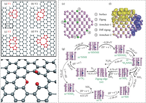
Transition metals possess unoccupied nonbonding d orbitals with a high electron density, which can serve as electron donor sites, promoting the NRR. Transition metal-based materials can donate electrons to the π∗ orbital of the N≡N molecule, facilitating nitrogen adsorption and weakening the N≡N bond. However, it is important to note that the presence of transition metal d orbital electrons also promotes the formation of metal–H bonds, which can enhance the competitive HER while potentially limiting the catalytic efficiency of the NRR [68]. As an alternative, nonmetal elements with abundant valence electrons may offer a more favorable environment for nitrogen activation as well as efficient selectivity due to weak H adsorption (Figures 7(a), 7(b), 7(c), and 7(d)) [19, 69, 70]. Zhang et al. utilized exfoliated few-layer black phosphorus (P) nanosheet as a nonmetallic catalyst for NRR. P (3s22p3) is a potential candidate for NRR as its valance electron structure is similar to that of the N (2s22p3) [71]. Exfoliated few-layer P provides a maximum number of intrinsic active sites for NRR (Figures 7(e), 7(f), and 7(g)).
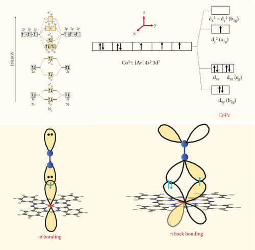
The nonmetallic component in transition metals reduces the hydrogen adsorption capability in the compound, thereby diminishing the hydrogen evolution reaction (HER) activity. Simultaneously, a sufficient number of valence electrons on the nonmetallic compound provide enough active sites for the nitrogen reduction reaction (NRR) process. Transition metal complexes, such as FePc and CoPc, with the assistance of nonmetallic components like phthalocyanine (Pc), are utilized to enhance NRR activity for ammonia (NH3) production [72–74]. Reducing nitrogen presents significant challenges due to its high bond energy, a substantial energy gap between the highest occupied molecular orbital (HOMO) and the lowest unoccupied molecular orbital (LUMO), and a large ionization potential. Paul et al. demonstrated that the d orbital of the CoPc molecule forms a σ bond with N molecules, utilizing the lone pair of electrons from the N atom (Figure 8) [72]. Additionally, π–back bonding occurs when the π∗ orbital of the N2 molecule accepts electrons from the filled d orbital (eg). Consequently, the N2 molecule can readily attach to the metal center of CoPc, a process facilitated by the combined effects of σ bonding and π–back bonding [72].
In a study by Murmu et al., the nitrogen adsorption energy with d-band center for the NiPc electrocatalyst in NRR and the correlated charge transfer mechanism between Ni and N2 were investigated [75]. The study reveals that the weak binding of NNH intermediates on carbon, pyrrolicN3,N2, and pyridonicN1 is the reason for the higher free energy and overpotential for NNH∗ than the Ni center in NiPc. The Ni center in NiPc exhibits the lowest overpotential of 1.22 V, compared to pyrrolic N3 (1.65 V), pyrrolic N2 (1.79 V), pyridinic N1 (1.77 V), and carbon (2.29 V). The researchers also discovered that the overpotential of NRR (1.22 V) is lower than that of HER (1.37 V) for the Ni center in NiPc. It appears that for Ni-Pc, the d-band center in the density of states (DOSs) shifts toward negative directions after the adsorption of N2 (–1.63 eV) and NNH intermediates (–2.23 eV). The electron accumulation on the N–Ni bonds for N2 and NNH favors nitrogen reduction. The overall scenario demonstrates that the Ni center in NiPc is the optimal active site and suppresses the HER [75].
Current research is primarily centered on optimizing electrocatalysts based on disordered noble and transition metals through manipulation of their shape, size, and composition for the purpose of NRR [76]. Unfortunately, traditional disordered catalysts often exhibit limited activity and stability (Table 2) [77]. Conversely, an ordered electrocatalyst structure can result in stronger electron interactions and have a notable impact on bond lengths, thereby influencing the electrocatalytic performance [78, 79]. Additionally, maintaining high enthalpy mixing in ordered structures contributes to enhanced stability [80]. Tong et al. developed an ordered body-centered cubic (BCC) Pd–Cu electrocatalyst that demonstrates impressive performance, with an NH3 yield of 35.7 μg h–1 mgcat–1 and a faradaic efficiency of 11.5%, at -0.1 V vs. RHE (reversible hydrogen electrode) [81]. In this context, a robust d–d coupling between Pd and Cu sites connects the coulomb gap related to electron transfer, enabling efficient NRR.
| Materials | Cycling stability test | Ref |
|---|---|---|
| MoO2-C nanoball flower | NITRR: 48 h stable performance | [39] |
| Fe-MoSe2 nanosheet/C18thiol | NRR: 5 cycles stable (35 μg h–1 mg–1 NH3 yield rate) | [37] |
| FeNi LDM | NITRR: 5 cycles stable 95% nitrate removal | [287] |
| CuO NWAs@4 | NITRR: 6 cycles 1.6 mmol–1 cm–2 NH3 yield rate | [280] |
| Co1/MoS2 | NORR: 10 cycles (210 μg h–1 cm–2 NH3 yield rate) | [176] |
| TiN/g-C3N4 nanohybrid | NRR: 5% reduced NH3 yield rate after 5 cycles | [41] |
| Hexagonal–Co nanosheet | NORR: 5% reduction of FE after 6 cycles | [168] |
| Ru-GDY | NRR: 17% reduced NH3 yield rate after 600 h | [139] |
| Co–N-Carbon | NITRR: 23% reduced NH3 yield rate after 50 cycles | [277] |
| Co–TPA | NITRR: 15 cycles stable NH3 yield rate | [244] |
| Fe1-Sx-TiO2 | NRR: 6 cycles stable NH3 yield rate | [58] |
| Pd–CuO nano-olives | NORR: 7% reduced NH3 yield rate after 5 cycles | [271] |
Morphological modulation proves to be an effective strategy for obtaining specific surface facets and active site densities that favor catalytic activities [82]. The presence of oriented spikes on the surface generates a focused electric field at the sharp tips, facilitating the concentration of reactants nearby and promoting catalytic reactions [83, 84]. Zhou et al. designed a dendritic Cu nanostructure with well-oriented nanospikes, leading to efficient catalytic NRR with a NH3 yield rate of 25.63 μg h–1 mgcat–1 and a FE of 15.1% at –0.4 V vs. RHE [82]. The Du group demonstrated that the thickness of the Cu layer influences catalytic activity; increasing thickness hinders mass transfer [85]. Cu with a monolayer, however, exhibits a lower mass transfer barrier and a mass activity of 12 μg h–1 mgcat–1 at 0.0 V vs. RHE.
The Shi group investigated the Cu2–xS/MoS2 catalyst through the epitaxial growth of the MoS2 layer on Cu2–xS quantum dots (QDs) for NRR performance, mimicking the natural nitrogenase active sites [86]. The selectivity in NRR improved due to the threefold coordinated Cu sites (Cu1.81S) [87]. The core-shell structure exposes Mo and Cu active sites more efficiently for electrochemical NRR, thereby increasing the charge transfer rate. The rate-limiting step is ∗NH + e– + H+ → ∗NH2, and the energy barriers for MoS2 and Cu2–xS/MoS2 are 1.5 and 0.98 eV, respectively [88, 89]. MoS2 is more prone to HER than Cu2–xS, so it is crucial to control the thickness of MoS2 on the core QD Cu2–xS [90].
In the case of transition, metal binds the N2 too weakly but binds the NH3 too strongly, which is imperative for a trade-off. A catalyst should bind molecules or atoms with intermediate strength. It should not be too weak, as this might fail to activate the reactants, nor too strong, to allow for desorption. This concept reflects a volcano-type relationship between activity and bond strength based on the Sabatier principle [91, 92]. Additionally, the d orbital electrons in transition metals contribute to the formation of metal-H bonds, promoting the hydrogen evolution reaction (HER) and, as a consequence, reducing faradic efficiency [76]. Balancing energy in the critical electrocatalytic steps involves modifying the catalyst’s microenvironment through the engineering of O vacancies [93]. This modification can reduce the activation energy barrier and enhance electron transfer at the interface. Yang et al. employ Fe3C/Fe3O4 heterojunctions in the nitrogen reduction reaction (NRR) [94]. Fe3C plays a crucial role by creating O vacancies on Fe3O4, which serve as active sites for NRR, enhancing the adsorption strength of N2. Fe3C/Fe3O4 heterojunctions paves the distal mechanism of the NRR [94].
Fang et al. developed a freestanding cathode by growing graphdiyne nanosheets on cobalt nitride nanowires in situ. This innovative approach led to impressive results, achieving an ammonia yield rate of 219.7 μg h–1 mgcat–1 and a Faraday efficiency of 58.6% at –0.2 V vs. RHE [95]. Graphdiyne is a unique two-dimensional carbon allotrope known for its porous structure, uneven surface charge distribution, electrochemical stability, and high conductivity. Cobalt nitride (Co2N) serves as an active electron-pumping center, and the interface with cobalt sites effectively transfers electrons to the graphdiyne layer. The presence of the graphdiyne layer enhances electron transfer toward N2. An unusual reduction in the d-to-pσ ∗ state transition (p–d coupling) reduces the barrier for initiating the optimal electrochemical nitrogen reduction reaction [95].
Titanium-based materials are promising electrocatalysts due to their stronger affinity for binding to nitrogen (adsorption energy: –2.7 eV). In contrast, their affinity for binding to hydrogen is lower (adsorption energy: –0.9 eV) [96]. In addition, doping TiO2 creates oxygen vacancies that promote N2 activation rather than the hydrogen evolution reaction (HER) [97]. Li et al. demonstrated that lattice strain on Ti3+ sites is more conducive to N2 activation than pristine TiO2, resulting in an NH3 yield rate of 5.5 μg h–1 cm–2 and a faraday efficiency of 26% at –0.6 V vs. RHE [98].
Liu et al. investigated on P-doped Fe-Ni-layered double hydroxides (LDHs) supported on carbon nanofibers for NH3 production. Their study revealed an ammonia yield rate of 1.7 × 10⁻¹⁰ mol s–1 cm–2 and a faraday efficiency of 23% at –0.5 V vs. RHE [48]. P doping reduces the electron density around metallic sites, promoting empty d–d orbitals.
Palladium- (Pd-) based catalysts facilely generate α-palladium hydride, a key intermediate initiating the NRR process via the hydride transfer pathway [99]. In pursuit of enhanced catalytic activity, metalloid boron (B) is introduced via doping, facilitating weak hydrogen adsorption and inducing rich valence electrons. This strategic introduction results in an intrinsically more catalytically active surface, fostering N reduction while mitigating the HER. Moreover, B doping on Pd stimulates electron transfer between the p orbitals of B and the d orbital of Pd, thereby optimizing nitrogen adsorption on the catalysts [100, 101]. In an effort, Wang et al. successfully synthesized a B-doped nanoporous Pd film on a nickel foam (Ni foam) substrate [102]. This engineered catalyst exhibited a considerable ammonia yield of 29 μg h–1 mgcat–1 and 17.9% FE under neutral conditions at –0.1 V vs. RHE. The self-supported nanoporous architecture, crafted with the assistance of micelles, provides an intricate network of numerous active site transfer channels [102].
Xu et al. have developed nanoporous Pd–H catalysts for NRR under ambient conditions [103]. In this process, the formation of ∗N2H (dinitrogen hydride) involves rate-limiting steps. The presence of hydrogen in Pd–H catalysts significantly enhances both catalytic activity and selectivity compared to pristine Pd. The hydrogen atoms in Pd–H actively participate in the formation of ammonia (Figure 9). The reaction involves the interaction between adsorbed nitrogen on Pd and hydrogen extracted from the outermost Pd–H lattice. This interaction results in the creation of hydrogen vacancies, which play a crucial role in activating water molecules. Notably, Pd–H (with an energy of 0.65 eV) leads to a lower Gibbs free energy (ΔG) for the formation of ∗N2H compared to pristine Pd (with an energy of 0.91 eV) [103].
The Zhang group also designed and synthesized palladium hydride nanorods (PdH0.43 NRs) as an electrocatalyst for NRR, demonstrating a 17.5 μg h–1 mgcat–1 ammonia yield rate and an 18.5% FE in a neutral electrolyte at –0.2 V vs. RHE [104]. The use of 1D palladium hydride proves advantageous for efficient electroreduction in ammonia production. One-dimensional materials, characterized by a high aspect ratio, inherent anisotropy, and faster charge/mass transport, contribute to the enhanced performance in electrocatalysis [105, 106].
Strategically, single-atom catalysts (SACs) are prepared by anchoring isolated noble metals (Ru, Pd, and Au) or transition metals (Mo, Cu, Fe, Fe/Zn, and Co) onto a conductive carbon-based solid support to achieve efficient catalytic activity in the NRR. These single atoms stabilize through M-Nx, M-Ox, or M-Cx coordination bonds with the carbon support, allowing precise control over NRR reaction pathways [107, 108]. Additionally, the introduction of alternative dopants such as Fe, Zr, V, and Cu into metal oxides creates oxygen vacancies that serve as active sites, promoting nitrogen adsorption and reducing the energy barrier for NRR [109, 110]. Chen et al. have mimicked the natural nitrogenase enzyme by synthesizing S-coordinated Fe single-atom catalysts on TiO2, adopting a lattice-confined strategy to enhance efficient electrocatalytic NRR [58]. The Fe1Sx@TiO2 catalyst exhibits an NH3 yield rate of 18.3 μg h–1 mgcat–1 with a faradaic efficiency (FE) of 17.3% at –0.2 V vs. RHE [58].
NRR faces challenges from the competitive HER, whether it involves hydrogen evolution (Volmer and Heyrovsky steps: 2H+ + 2e– → 2H∗ → H2) or the initial hydrogenation step of NRR (∗NN → ∗NNH) [111, 112]. The selectivity of NRR can be guided by suppressing the adsorption of H+ on the catalysts. Chung et al. devised a catalyst composed of carbon nanofibers embedded with Co and Mo, denoted as Co–Mo–CNF [57]. By harnessing the varying adsorption strengths of the catalysts, Co serves as a robust catalyst for water dissociation, providing a local proton source in the vicinity of Mo, where the NRR takes place. In the Co–Mo–CNF catalyst, water dissociation at the Co catalyst sites supplies concentrated protons to the nearby N atoms, which are adsorbed at the Mo catalyst sites, promoting the selective hydrogenation of ∗N–Mo. Consequently, Co–Mo–CNF exhibits an NH3 formation rate of 72.7 μg h–1 mgcat–1 and achieves a Faradaic efficiency of 34.5% at –0.5 V vs. RHE, compared to only 48 and 10 μg h–1 mgcat–1 for Mo–CNF and Co–CNF, respectively [57]. The Wu group prepared a unique sub-monolayer of MoS2–x, generating in-plane S vacancies [113]. These S vacancies create compressive strain effects, allowing for the efficient activation of N2 and adjustment of N intermediates’ affinity, thereby tuning the catalytic properties. Additionally, the strong H adsorption at the 2D surface suppresses the competitive HER process [113]. Zi et al. designed and utilized a single-layer MoS2 with S vacancies coated on MoO3 (SV–1 T–MoS2@MoO3) [114]. The charge density difference reveals a depletion of electrons in the MoO3 matrix, promoting the transfer of charge from MoO3 to MoS2 in the SV–1 T–MoS2@MoO3 catalyst. This facilitates fast reaction kinetics on the surface. Moreover, the charge transfer from N2 to the bare Mo atom favors the formation of Mo–N bonds, lengthening the N–N bond from 1.10 Å to 1.13 Å due to N2 activation by the S vacancies. Simultaneously, this hybrid configuration prevents the agglomeration of MoS2 and enhances the stability of the catalyst. The hybrid catalysts exhibit a superb NH3 yield rate of 116.1 μg h–1 mgcat–1 and 18.9% FE at –0.2 V vs. RHE [114].
The Meng group encapsulated oxidized CoP particles in carbon nanotubes (O–CoP/CNT) and utilized them as NRR catalysts, demonstrating a NH3 yield of 39.5 μg h–1 mgcat–1 and a FE of 19.4% at –0.5 V vs. RHE [115]. Oxygen-rich CoP stabilizes N intermediates (NH–NH, NH2–NH, and NH2–NH2) through H bonds, enhancing NRR activity. Additionally, the hydrophobic nature of CNT inhibits proton contact with the catalyst surface, promoting the hydrogenation of N intermediates [115].
The consideration of metal-free catalysts for NRR arises due to the scarcity of transition metals and the extensive hydrogen evolution reaction associated with them. However, it is worth noting that the performance of metal-free catalysts in NRR is often unsatisfactory due to the lack of dedicated active sites [116, 117]. Lin et al. explored the use of defective boron carbon nitride (BCN) for NRR electrocatalysis [118]. The empty sp2 orbital of boron (B) can interact with the lone pair of N2, activating and adsorbing N2, thereby hindering the binding of H+ ions and suppressing the competing hydrogen evolution reaction (HER). BCN, with its unsaturated B and N atoms, serves as dual catalyst sites, forming frustrated Lewis pairs (FLPs) that can adsorb, activate, and selectively catalyze NRR (Figures 10(a) and 10(b)). In this context, the adjacent electron-deficient boron and electron-rich nitrogen transform the single Lewis acid catalyst into FLPs, resulting in an ammonia yield rate of 20.9% and an 18.9% faradaic efficiency (FE) at –0.1 V vs. RHE. FLPs facilitate the adsorption of nitrogen, forming a six-membered intermediate ring, which can break down N2 through pull-pull effects. As a consequence, this significantly reduces the energy barrier for the rate-limiting steps in the NRR process [118].
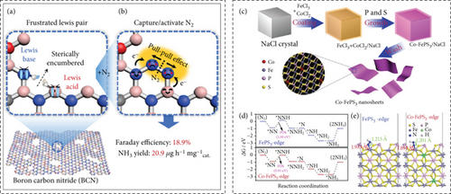
Wu et al. consider the earth-abundant and low-cost non-noble-metal tri-manganese tetraoxide (Mn3O4) nanocubes as electrocatalysts for NRR at ambient conditions. The catalyst shows the NH3 yield of 11.6 μg h–1 mgcat–1 and FE of 3% at –0.8 V vs. RHE [119]. Huang et al. utilized 2D Co-doped FePS3 (Co–FePS3) nanosheets as an electrocatalyst for NRR [120]. In biological nitrogen fixation nitrogenases, Fe-S (iron protein) plays a critical for electron transfer. Also, the P cluster is an inevitable constituent as its bridging elements for transfers of electrons from Fe-S to the substrate [121–123]. Based on the understanding of the nitrogenase process, 2D FePS3 is employed for the NRR process (Figures 10(c), 10(d), and 10(e)). Cobalt (Co) incorporation enhances the conductivity as well as catalytic activity at Fe-edge sites. Co-FePS3 shows NH3 yield rate of 90.6 μg h–1 mgcat–1 (29 μg h–1 cm–2) and FE of 3.38% at –0.4 V vs. RHE [120]. Hao et al. consider isolated Pt on WO3 nanoplates (Pt SAs/WO3) for electrochemical fixation of N2 [124]. Single-atom active sites are believed to suppress the strong HER. Pt-based electrocatalyst shows strong HER activity due to the surface of Pt nanoparticles readily adsorbed H atoms than N2 at negative potential [125]. Excessive adsorption of H atoms promotes the HER and suppresses the NRR process in Pt nanoparticles for occupying the active sites by H [126, 127]. In Pt nanoparticle, ∗H adsorption (ΔG(∗H) = −0.70 eV) is much spontaneous than N2 adsorption (ΔG(∗N2) = −0.17 eV). Here, ∗H adsorption energies ΔG(∗H) on the isolated Pt sites for Pt–3O, and Pt–2O are –0.94 and –0.82 eV, respectively, for Pt SAs/WO3. In the case of ∗N2, adsorption energies ΔG(∗N2) for Pt–3O and Pt–2O are –1.34 and –0.30 eV, respectively, which shows that the N2 adsorption could be less hindered by the ∗H adsorption if the Pt incorporate as single atom on the catalysts. Also, ∗H adsorption on the WO3 (ΔG(∗H) = −2.39 eV) is so strong that could not initiate the HER process on the catalyst [124].
Tan et al. designed the electrocatalyst of Au25–Cys–M (M: Mo6+, Fe3+, Co2+, Ni2+) for the NRR process. Here, Mo6+, Fe3+, Co2+, and Ni2+ are atomically decorated on Au25 nanoclusters via thiol bridging [128]. Among Mo6+, Fe3+, Co2+, and Ni2+, Au25–Cys–Mo catalyst shows the highest catalytic efficiency of FE (26.5%) and NH3 yield (34.5 μg h−1 mgcat−1) in 0.1 m HCl solution. Formation of Au–S and Mo–S interactions that modulated the electronic structure of Mo sites helps to activate N2. Also, Mo sites promising for the conversion of adsorbed N2 molecules as well as the desorption of NH3 [128].
Cu generally shows weak NRR activities due to weak binding to N-containing intermediates [82]. Forming heterojunction by optimizing charge distribution or oxygen vacancies or improving surface hydrophobicity inhibits the hydrogen evolution or results in electron-rich active sites for increasing adsorption and activation of the NRR process [129, 130]. In the case of CeO2, flexible oxidation state transition properties of CeO2 between Ce3+ and Ce4+ show drastic electronic interactions with the catalysts [131, 132]. CeO2 coupling with electrocatalyst boosts the electrocatalytic performance and induces O vacancies on the CeO2 promoting it to NRR active substance [133, 134]. Jing et al. developed Cu2O–CeO2–C nanorods on Cu mesh by MOF templated for the NRR process [135]. Cu2O–CeO2 construction provides the formation of interfacial Cu–[Ox]–Ce structure, where the removal of the O atom in Cu–[Ox]–Ce to form Cu–[Vo]–Ce of oxygen vacant catalyst. Here, Cu–[Vo]–Ce gives the highest free energy of ∗H adsorption (0.52 eV) and results in the lowest HER activity than Cu2O with oxygen vacancy (0.32 eV) and Cu-doped CeO2 with 1 oxygen vacancy (0.46 eV). Cu2O–CeO2–C provides an NH3 yield of 6.37 × 10⁻³ μg s−1 cm−2 and a FE of 18.21% at −0.3 V vs. RHE [135].
Liu et al. developed an n-n heterojunction of Cu–N and B–N dual active sites by in situ growth of a conductive MOF on hexagonal boron nitride [136]. Here, heterojunction can modulate the band gap energy and density of state near the Fermi level which effectively improves the electron capability to reduce intermediates of electrocatalytic NRR. The catalysts show the146 μg h−1 mgcat−1 NH3 production and 42.5% FE efficiency due to amounts of oxygen vacancies, porosity, and dual active sites [136].
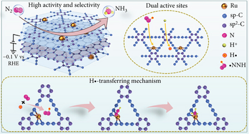
Perovskite oxides are utilized in electrocatalytic activities due to their high conductivity and the capacity to modify A-sites and B-sites [137]. These modifications induce oxygen vacancies, influencing N2 adsorption and activation. Both Ru single atoms and Ru cluster–embedded perovskites exhibit efficient electrocatalytic activity, with an NH3 yield rate of 137.5 μg h−1 mgcat−1 and a FE of 56.9% [138]. The Ru cluster modifies the electronic structure of the Ru single atom, reducing the energy barrier for the initial hydrogenation (∗NN → ∗NNH) in ammonia generation [138]. Ru single atoms anchored on graphdiyne (GDY) generate H radicals (•H) and consecutively activate nitrogen to produce NNH radicals (•NNH) (Figure 11(a)) [139]. Here, combined dual-active sites are employed, with GDY acting as H adsorption sites and Ru acting as •NNH adsorption sites. The dedicated catalyst (Ru SAs/GDY/G) exhibits a production rate of 56.8 μg h−1 mgcat−1 (4.7 mg h−1 mgRu−1) and a FE of 37.6% at –0.1 V vs. RHE [139].
Hollow hierarchical nanotubes of cobalt vanadium phosphide (CoVP) @NiFeV-LDHs were designed, with NiFeV ternary LDHs growing in situ on the hollow tube of CoVP [140]. The inclusion of phosphorus on the transition metal (TM) enhances N2 reduction by weakening the N≡N bond and strengthening the TM-N bond. The ion transport path is shortened by the hollow nanotube, providing maximum active exposed sites. This is due to the accessible surface area for water and nitrogen reactants, facilitating the reaction [140]. The Ren group investigated N, B codoping on porous carbon for nitrogen reduction reaction (NRR) (Figure 11(b)) [141]. They observed that the porous structure of carbon facilitates the trapping of N2 and stabilizes intermediate reactants (N2Hy). Additionally, B doping promotes the formation of pyridinic N and B–N bonds, both of which effectively enhance NRR activity [141]. Wang et al. similarly designed hollow bimetallic CoFe2O4 nanocubes wrapped in a thin carbon (C) layer and modified with O vacancies [142]. The binding energy of the nanocubes in C@CoFe2O4–x is higher than that of pure CoFe2O4. The strong adsorption capability of N2 is beneficial for initiating the NRR, attributed to the synergetic effects of O vacancies and the presence of wrapped carbon [142].
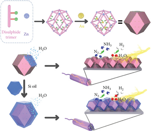
Au serves as an excellent electrocatalyst, as N2 adsorbs on the Au surface, promoting the hydrogenation of N intermediates to generate N2Hx (x = 1 to 4) species [143, 144]. The Sun group synthesized well-dispersed ultrafine nanoparticles of Au (1.9 nm) on the MOF (Zn (II) constructing a 3D disulfide trimer), where the MOF acts as host material with high porosity and stability (Figure 11(c)) [145]. Au@MOF surfaces were modified with organosilicon to induce hydrophobicity. Here, sulfides serve as carriers for Au nanoparticles, and the hydrophobic organosilicon limits competitive HER [145].
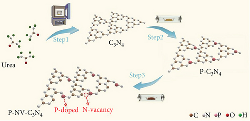
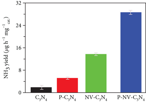
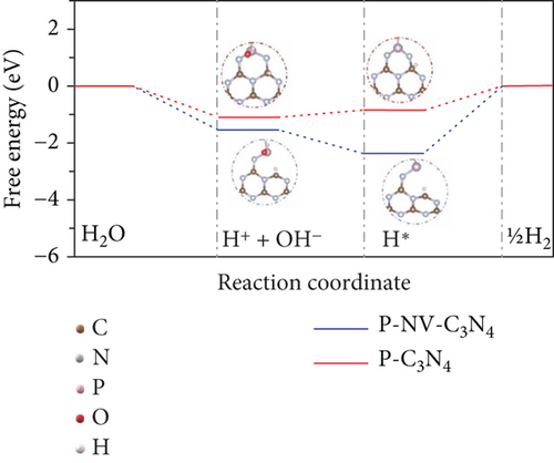
The pristine form of carbon nitride (CN) demonstrates limited catalytic activity for the NRR process, primarily due to a lack of catalytically active sites. However, its intrinsic properties offer an opportunity for straightforward regulation, potentially leading to favorable catalytic characteristics. This is attributed to the material’s inherent stability and a high content of nitrogen-rich sites (N-rich) [146]. The Zhao group investigated the potential of nonmetal phosphorus (P) doping on CN as an NRR catalyst (Figure 11(d)) [147]. The study involved the synthesis and preparation of P-doped CN with a rich nitrogen vacancy (P–NV–CN) catalyst, demonstrating a substantial ammonia yield rate of 28.6 mg h−1 μgcat−1 and a FE of 22.1% at –0.3 V vs. RHE. The nitrogen vacancy (N vacancy) inhibits the HER of Heyrovsky steps (∗H → H2) and promotes N2 adsorption and activation. Nitrogen vacancy effect is attributed to the enriched electron density around the N vacancy, facilitating transfer at the unoccupied 2π ∗ orbits in N2. The P doping contributes to catalytic water splitting, providing a source of hydrogen (H) for the hydrogenation of nitrogen. The synergistic effects of the P–NV–CN catalyst reduce the energy barrier of the potential determining step of NRR and contribute to the stabilization of reaction intermediates [147].
Arif et al. developed an electrocatalyst comprising CoFeB nanospheres wrapped around the edges of reduced graphene oxide (rGO) nanosheets, forming a CoFeB@rGO heterostructure [148]. The strategic positioning of CoFeB nanospheres along the edges significantly improved catalytic activity, providing a higher surface area, more accessible active sites, and facilitating fast electronic transfer between the rGO nanosheets and CoFeB nanospheres. The ultrathin rGO encapsulating the CoFeB nanospheres enhances the structural stability of the nanospheres, while the interconnected nanosheets contribute to improved conductivity. CoFeB plays a crucial role in lowering the energy threshold for N2 adsorption and protonation. The synergistic effects of the electrocatalyst result in a FE of 31.6% and an NH3 yield rate of 35 μg h–1 mg–1 at –0.2 V in 0.05 M H2SO4 [148].
Mushtaq et al. have developed a hierarchical heterostructure hollow microsphere composed of Mo-doped WO3@CdS, achieved through the in situ growth of dispersed CdS nanoparticles onto Mo-WO3 for the purpose of photoelectrochemical NRR to produce NH3 [149]. The introduction of Mo doping on WO3 effectively reduces the energy barrier for nitrogen activation and protonation. The resulting photoelectrocatalyst demonstrates a FE of 36.7% and an ammonia yield rate of 38.9 μg h–1 mg–1 at –0.3 V vs. RHE in neutral solution under ambient conditions. The hollow structure of the microsphere offers advantages, allowing for multiple scattering of sequentially absorbed light to enhance light harvesting capabilities. The voids within the structure provide abundant surface areas for catalytic reactions. The Mo-W dimer serves as an active center for N2 adsorption and facilitates the rapid generation of ∗NNH. The incorporation of Mo doping and the presence of O vacancies contribute to a decreased overpotential (1.48 eV) compared to pure WO3 (1.82 eV). CdS aids in the swift transfer of photogenerated electrons from CdS to Mo-WO3, thereby accelerating the photoelectrochemical performance. The observed slow photon light scattering effects effectively increase light absorption ability, decrease charge transfer distance, and mitigate the recombination of photogenerated charges. Additionally, plasmonic nanoparticles of MoO2 and MoO3–x within the hollow structure attribute localized surface plasmon resonance effects. The synergetic effects improve the NH3 yield [149].
In another study, Mushtaq et al. also synthesized a hybrid micro/nanostructure of MoSe2@g-CN. The hierarchical micro/nanoflowers of MoSe2, integrated with exfoliated g-CN nanosheets, demonstrated a photoelectrocatalyst with a 28.9% FE and a 7.7 μmol h–1 cm–2 ammonia yield rate at –0.3 V vs. RHE in a 0.1 M KOH electrolyte [150]. The Mo atoms in MoSe2 served as the primary catalytic active sites, while g-CN facilitated the photoexcited electrons for the N2 reduction process. The flower-like micro/nanostructure of MoSe2 enhanced light harvesting capability, mass transport, and charge separation efficiency. The homogeneous dispersion of g-CN played a crucial role in forming a heterojunction, promoting interfacial charge transfer, and enhancing the efficiency of electron-hole pair separation. This synergy effects contributed to a reduced recombination rate, extending the lifetime of photoinduced electron-hole pairs. Simultaneously, g-CN provided active sites for N-containing groups, such as pyrrolic and pyridine N, supporting the NRR [150].
Single-metal moiety (M–N4) is utilized for the various catalytic activities. The high electronegativity of the systematic bordering of nitrogen atoms around metal sites could result in the improper adoption of energy for the intermediate species. Zhao groups designed noble catalyst, introduced the sulfur, removed the one nitrogen atom from the M–N4, and created an asymmetric atomic boundary to obtain an enhanced kinetics effect. Dual metals anchoring onto heteroatom-doped C (Fe/Co–atom microenvironment with N/S atom) electronically engineered microenvironments of active sites efficiently standardize the distribution of local charge density of the catalyst and implicate the synergetic effects and enriched active center on the catalyst [151].
Defects in porous catalysts definitively induce modifications in the catalyst’s active sites. Combining these defects with heteroatom doping can enhance the localization state and bring it closer to the Fermi level. This atomic modulation approach, which involves edge/surface modifications, graphitization, and heteroatom doping, influences the spin/charge status and significantly improves the performance of oxygen reactions [152]. Furthermore, strategies for the precise control of the microenvironments of single-atom catalysts (SACs) have the potential to facilitate various catalytic modulations by controlling the coordination environment and electronic states [153]. Adjusting the coordination environment can standardize the d-band center of the central atoms, which helps to enable different density transfers and optimize the adsorption and desorption properties of various intermediates. Tuning the coordination number is utilized to activate synergistic catalytic properties. Engineering surface defects prevent the aggregation of SACs by increasing charge transfer between the single atom and the defects. Dual metal coordination induces a synergistic interaction and redistributes electron density, and altering the metal charge state can result in superior catalytic activity [154]. Multistep catalytic reaction is limited by the linear scaling relationship of the adsorbate, even though the SACs by heteroatom doping, the addition of p-sites, and lowering coordination numbers were not able to break the linear scaling relationship of multistep catalytic activity. However, a heteronuclear dual-atomic catalyst could be a promising model for different metal sites at the distance limit of the electronic interaction and could offer different interactions to break the linear scaling relationship of multistep catalytic activity [155]. Crystal facet engineering by rational order, effective atomic structure, and synchronization of crystal facet could be an alternative model to improve the electrocatalytic NRR activity. The optimal and exposed facet could improve the adsorption and catalytic activity [156].
Nitric oxide and hydrazine are byproducts of the nitrogen reduction reaction, and high selectivity for ammonia production is essential. Hydrazine production can be anticipated through associative alternating pathways [157]. Dissociative and distal pathways may reduce the formation of hydrazine byproducts. Additionally, it needs to be considered that multiple catalytic steps involve numerous intermediates, each with adsorption energetic relationships, termed scaling relations [92, 158]. Unfavorable scaling relationships among intermediates can make achieving optimal products or selectivity challenging [91]. Countering the effects of unwanted byproducts or achieving higher selectivity requires designing active sites with optimal adsorption energy of the intermediates by changing the binding configurations of energy. The integrity of the homogeneous distribution of catalytic active sites while maintaining the perfect and precise synthesis protocol of catalyst material is paramount to reducing byproducts and facilitating the efficient formation of selective products [157].
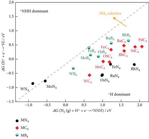
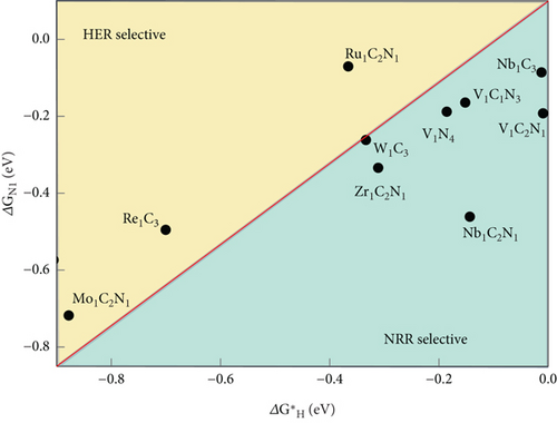
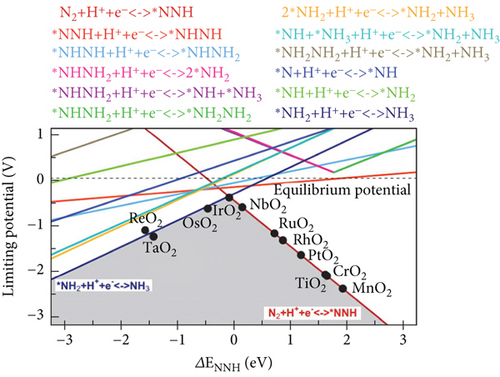
In the NRR electrocatalytic process, challenges arise for competitive HER due to the high surface coverage of ∗H on the active atomic sites. Poor selective NRR is a result of the high coverage of adsorbed H on pure metals, hindering the active sites for the NRR. The adsorption Gibbs free energy difference among ∗H, ∗N2, and ∗NNH serves as the theoretical descriptor for the first steps of the NRR, whether it is N2 adsorption or NNH formation (Figure 12) [159]. In Figure 12(b), the atomic site catalyst (ASC) mint region shows that ΔGN2–ΔGH is negative, implying that nitrogen adsorption is favorable, and higher NRR selectivity is expected. The reaction with lower free energy is more selective. In this context, the HER is more selective for Re1C3, Mo1C2N1, and Ru1C2N1 than NRR [160]. Long et al. have demonstrated that N2 + H+ + e− → ∗NNH is the first step of the NRR process, and the selectivity descriptors include ΔG[N2 (g) + H+ + e−⟶∗NNH] − ΔG(H+ + e−⟶∗H) [161]. It is observed that in the lower right area, where ΔG[N2 (g) + H+ + e−⟶∗NNH]˃ΔG(H+ + e−⟶∗H), ∗H is preferred, and HER is favorable, while NRR is hindered (Figure 12(a)). On the other hand, in the upper left area of the figure, ∗NNH adsorption dominates, resulting in higher NH3 selectivity [161]. The NRR volcano is governed by two elementary reaction steps. Volcano plots were constructed using the scaling relation between the binding energies of various intermediates in the NRR process on transition metal oxide (Figure 11(c)) [162, 163]. Electrochemical ammonia formation potential determining steps (PDS) on transition metal oxide are plotted against ΔENNH (binding energy of NNH). The mechanistic descriptors on the left leg provide insight into ammonia formation, while the right leg elucidates the formation of the ∗NNH adsorbate with potential determining steps. These descriptors offer a general understanding of the phenomena underlying the NRR process on solid-state electrodes. Hydrazine is a competitive side reaction in the volcano plots. Weak bindings of ∗NNH and catalyst, along with hydrazine formation, compete with ammonia formation [162].
5.2. Nitric Reduction Reaction (NORR)
5.2.1. Strategical Material Design for NORR
Long et al. conducted a study employing density functional theory (DFT) to explore the selection of an efficient electrocatalyst for the nitrogen oxide reduction reaction (NORR) [170]. Their research revealed that copper (Cu) exhibits higher NORR activity than nitrogen reduction reaction (NRR) while maintaining superior selectivity for ammonia over hydrogen production. Experimental results demonstrated that a Cu foam electrode achieved an electrochemical ammonia synthesis rate of 517.1 μmol h–1 cm–2 and a faraday efficiency of 93.5% at –0.9 V vs. RHE [170].
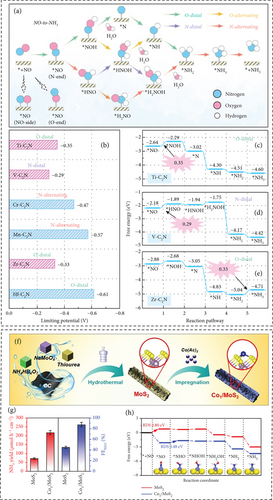
Single-atom catalyst was implemented for the NORR mechanism in perspective of the high metal utilization and catalytic efficiency [171]. Niu et al. employed density functional theory (DFT) to systematically screen efficient single-atom catalysts (transition metals, TM) within TM–C2N for the conversion of NO to NH3 (Figures 13(a), 13(b), 13(c), 13(d), and 13(e)) [172]. Among the 23 transition metals studied, spanning from Ti to Au, TM–C2N (specifically Ti, V, and Zr) exhibited promising nitrogen oxide reduction reaction (NORR) activity, with limiting potentials of –0.35 V, –0.29 V, and –0.33 V, respectively. Notably, among Ti, V, and Zr in TM–C2N, Zr–C2N emerged as a promising catalyst for NH3 production, effectively suppressing the formation of byproducts such as N2O, N2, and H2 [172].
Li et al. developed an electrocatalyst for the reduction of NO to NH3, consisting of a TiO2 nanoarray supported on a Ti plate (TiO2-x/TP) [165]. While TiO2 is known for being a cost-effective, eco-friendly, and highly durable material, its inherent limitations include low active sites and poor electrical conductivity, resulting in reduced catalytic activity [173]. To address these issues, the introduction of oxygen vacancies on TiO2-x and defect engineering enhances the availability of active sites. Additionally, the formation of nanoarrays serves to maximize catalytic sites, improving NO adsorption and activation (NH3 yield 1233.2 μg h−1 cm−2 at −0.7 V and FE 92.5% at −0.4 V in neutral media) [165]. Wang et al. designed and reported that hexagonal-closed-packed Co nanosheets (hcp–Co) show a unique electronic structure and proton shuttle effect that shows efficient NORR catalytic activity of 439.5 μmol h–1 cm−2 NH3 yield and 72.5% FE [168]. Zn-O batteries with hcp–Co were assembled as the cathode, and they performed better than what has been reported before, with a power density of 4.66 mW cm−2 [168].
MoS2 is considered a comparatively efficient electrocatalyst for the NORR, selectively converting NO to NH3 with an FE of 76.6% [174]. Notably, MoS2 edges exhibit catalytic activity, while the basal plane remains catalytically inactive [175]. Efficient NO adsorption and activation occur at these edge sites. Considering previous discussions, Co is recognized as an efficient element for catalytic NO reduction. Li groups introduced single Co atoms on MoS2 to induce catalytic activity on the basal plane (Figures 13(f) and 13(g)). The research yielded a robust and highly active catalyst, Co1/MoS2, providing an NH3 yield of 217.6 μmol h–1 cm–2 and an FE of 87.7% at –0.5 V vs. RHE. The energy barrier for the rate-determining step of NO adsorption on bare MoS2 is 0.80 eV [176], which significantly reduced to 0.48 eV on the modified Co1/MoS2. Additionally, the binding energy of hydrogenation intermediates on Co1/MoS2 is considerably lower than on MoS2. The presence of Co1–S3 moieties selectively activates and ultimately improves the catalytic activity of NORR [176].
Bai et al. designed and synthesized a hollow nanoreactor, Cu2O@CoMn2O4 (nanocube, with Cu2O entrapped in CoMn2O4), for NO reduction. In the synthesis process, different etching times were employed to control the formation of various structures [177]. The void confinement effects enhance the reactivity of reactants within the internal spaces of the nanoreactor, improving electron transfer efficiency. As the internal space increases, there is a greater concentration of intermediates within. The Cu site in Cu2O@CoMn2O4 exhibits the lowest energy barrier (0.6 eV) for the formation of ∗NOH, a crucial intermediate in the rate-determining steps of NO reduction. The 3d states of Cu in Cu2O@CoMn2O4 lie below the Fermi level and shift toward the Fermi level, making electrons more available and increasing their activity. The synthesized hollow nanoreactor demonstrates considerable electrochemical NO reduction activity, yielding an NH3 production rate of 94.1 mmol g−1 h−1 and FE of 75% at −0.8 V vs. RHE. The Tafel slope indicates that the Cu2O@CoMn2O4 nanoreactor with an etching time of 8 minutes (278 mV dec–1) before calcination at 350°C exhibits more favorable kinetics compared to etching times of 2, 3, and 8 minutes, which result in Tafel slopes of 449, 408, and 399 mV dec–1, respectively [177].
5.3. Reduction Reaction (NITRR)
5.3.1. Strategical Material Design for NITRR
A MXene-like layered structure is employed for electrocatalytic reactions, with its surface metal atoms passivated by various functional groups. An alternative approach involves the technical modification or removal of these surface functional groups to create a clean surface of metal atoms in MBenes (metal/boron materials), taking advantage of their physiochemical properties. This clean surface in MBenes promotes the full exposure of active metal/boron sites, enabling the efficient progression of tandem electrocatalytic reactions [183, 184]. Zhang et al. employ MBenes (FeB2) for electrocatalytic nitrate reduction to ammonia [185]. In this process, nitrogenous molecules are activated at the B-sites, while the metal Fe-sites facilitate water splitting (Figure 14). The Fe-active sites enhance water dissociation, leading to an increase in the production of ∗H, which subsequently spillovers from Fe to B, thereby enhancing the hydrogenation reaction in nitrate reduction to ammonia [185].
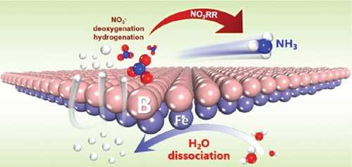
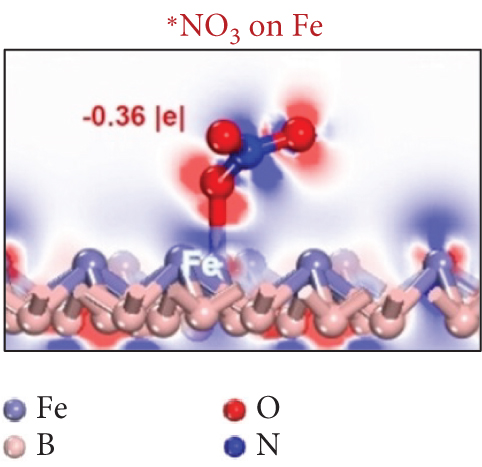
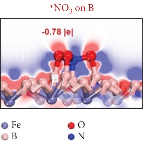
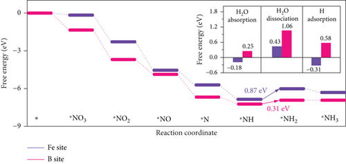
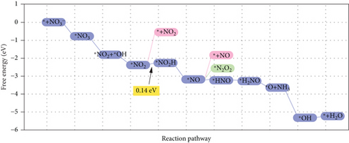
Single-atom catalysts (SACs) are used in nitrate reduction reactions because they offer improved atomic utilization efficiency and trigger specific electronic structure changes (Figure 15(a)). In the context of nitrate reduction, SACs overcome the challenge of N–N coupling (∗N intermediates), which typically occurs between two neighboring catalytic sites [186]. This is achieved through the presence of isolated metal active sites [187, 188]. A proposed strategy to enhance the catalytic efficiency involves a symmetric planar four-ligand structure (M–N4, where M can be Fe, Co, Cu, etc.) [189, 190]. However, it is important to note that if the four coordinated N atoms share electronic density symmetrically with the metal sites, it can have a detrimental effect. This symmetric distribution of electronic density can impede the adsorption and activation of intermediate species on the active sites, limiting the overall reaction kinetics and performance [191]. To address this issue, a strategic approach involves designing heterojunction materials and modulating the electronic structure of active sites by introducing heteroatoms such as P, O, and S. These heteroatoms play a critical role in efficiently accumulating and diffusing during the catalytic process. Xu et al. reported that Fe atoms, which atomically coordinated with N and P on a hollow carbon substrate (Fe–N/P–C), were used for nitrate reduction to produce NH3. This modification achieved a Faradaic efficiency (FE) of 93% and a yield rate of 1800 μg h–1 mgcat–1 at �0.8 V vs. RHE [18]. Modifying the presence of phosphorus (P) on the electrocatalyst increases the electron density around the iron (Fe) center. This adjustment has the potential to improve the adsorption and proton transfer processes of nitrate () ions and their intermediates on the catalyst’s surface. Ultimately, these changes contribute to enhanced catalytic performance [18]. Also, dual-atom catalysts (DACs) synergistically activate reactants and stabilize key intermediates in the complex multistep process (Figures 15(b), 15(c), and 15(d)). Zhao et al.’s group investigated homonuclear dual-metal catalysts on N-doped graphene (Cu2@N3–6) [192]. These catalysts exhibit an ammonia yield rate of 18.2 mg h–1 cm–2 and an FE of 97.4% at –0.8 V vs. RHE. The NITRR process and energy diagram show the following steps: → ∗NO3 → ∗NO2 + ∗OH → ∗NO2 → ∗NO2H → ∗NO → ∗HNO → ∗H2NO → ∗O + NH3 → ∗OH → H2O.
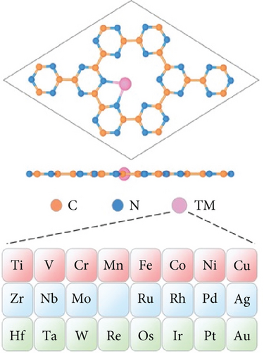
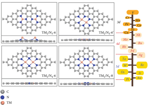

Cu-based catalysts are useful for catalyzing the reduction of nitrate to ammonia, but their performance is hindered by their vulnerability to poisoning by ∗NO2 intermediates, primarily due to strong adsorption, resulting in lower reaction activity and stability [193, 194]. Wu et al. used Zn-doped Cu catalysts to control the adsorption strength of N-containing intermediates (∗NO3, ∗NO2) at a moderate level, following the Sabatier principle [195]. Bare Cu exhibits top NO adsorption, while Zn doping on Cu increases the electron density on Cu and decreases it on Zn, leading to bridge adsorption of NO due to the higher oxygen (O) affinity to Zn. As a result, this promotes the breaking of N–O bonds and favors the formation of NH3 [195]. Wang et al. employed CuO nanowire arrays (NWAs) as a cathode material for the electrocatalytic reduction of nitrate (NITRR) [196]. They found that CuO NWAs underwent electrochemical conversion to Cu/Cu2O NWAs. Cu/Cu2O served as the active species for the NITRR process. Initially, nitrate adsorbed onto the catalyst to form ∗NO3. Subsequently, the N–O bond of ∗NO3 broke, leading to the production of ∗NO2 and ∗NO. During the hydrogenation steps, ∗NO transformed into ∗NOH, and further hydrogenation resulted in ∗NH2OH, which eventually transformed into ∗NH3. In the final step, ∗NH3 is desorbed from the catalyst. The formation of ∗NOH from ∗NO was identified as the rate-limiting step, characterized by a higher energy barrier in CuO NWAs. However, in Cu/Cu2O NWAs, this energy barrier was significantly reduced. Additionally, the electron density of Cu in Cu/Cu2O NWAs was lower compared to pure Cu. Consequently, Cu/Cu2O NWAs suppressed the hydrogen evolution reaction (HER), as the energy barrier for H2 formation in Cu/Cu2O NWAs (0.33 eV) was much higher than in CuO NWAs (0.12 eV) [197]. As a result, a high nitrate conversion rate (97%), ammonia yield rate (0.24 mmol h–1 cm–2), faradic efficiency (95.8%), and selectivity (81.2%) were achieved at 0.85 V vs. RHE [196]. Fang and Wang proposed the in situ formation of a new phase with atom defects, which could modify surface properties during electroreduction and potentially enhance the efficiency of the catalytic nitrate-to-ammonia process [186]. Their investigation unveiled that CuO can undergo in situ transformation into oxide-derived Cu, characterized by infused stacking faults and tensile strain. This transformation promotes increased Cu activity and enhances nitrate adsorption. The in situ generation of stacking faults proves effective for catalytic activation, providing insights applicable to various catalysts [186].
It is worth noting that while Cu-based catalysts demonstrate a high FE of over 90%, they operate at very negative potentials ranging from –0.4 to –0.7 V vs. RHE, which is energetically inefficient [196]. This negative potential is necessary to optimize the weak adsorption of hydrogen (H) on the Cu surface, ensuring sufficient coverage of ∗H to achieve a significant hydrogenation rate. However, it is expected that Cu-based catalysts could exhibit higher hydrogenation ability at more positive applied potentials [198, 199]. To address this challenge, Liu et al. explored the use of rhodium (Rh) clusters or single atoms on Cu nanowires [20]. Rh has excellent adsorption-desorption properties for hydrogen (H) and can compensate for Cu’s limited hydrogenation ability, thereby improving NITRR. As a result, the combination of Rh with Cu nanowires achieved an FE of 93% at –0.2 V vs. RHE and an ammonia yield rate of 1.27 mmol h–1 cm–2 at –0.4 V vs. RHE, outperforming pure Cu (100) catalysts which achieved only 0.65 mmol h–1 cm–2 at –0.15 V vs. RHE [20, 200]. The Zhang group dispersed small Au on Cu (111) nanosheets and introduced copper vacancies (VCu) [201]. Here, Vcu and single Au atoms work synergistically, where electron transfer from Cu to Au enhances the activation of H2O to ∗H and promotes nitrate hydrogenation kinetics.
The intrinsic catalytic activity and selectivity are enhanced through the modification or tuning of textural properties, considering size, shape, and specific morphological structure [202, 203]. Introducing a one-dimensional (1D) nano-wire-based structure proves beneficial for improving surface chemistry and electron transfer while eliminating issues such as agglomeration, dissolution, and Ostwald ripening of the catalyst [204, 205]. Furthermore, precise engineering of the metal–oxide interface through partial oxidation contributes to heightened catalytic activity by facilitating electronic interactions at the interface of metal and metal oxide [206–208]. Building on this assumption, the Ren group devised a Cu2+1O concave–convex layer on Cu nanowires [209]. The interior Cu components efficiently transmit electrons along the nanowire structure, and the concave–convex Cu2+1O layers offer abundant catalytic active surfaces. Electronic interactions between the metal and metal oxide in the interface tune the Cu d-band and modulate the adsorption energies of intermediates. Utilizing 1D nanowires helps prevent agglomeration, dissolution, and Ostwald ripening of the catalyst. Ultimately, the Cu/Cu2+1O catalyst achieved notable results, including a 78.5% nitrate conversion rate, 76% NH3-N selectivity, 87% FE, and 576.5 μg h–1 mgcat–1 of NH3 yield rate, respectively, at –1.2 V vs. SCE [209].
Groundwater and surface water are currently experiencing significant issues due to the increasing presence of low concentrations of nitrate, which can lead to acid rain and photochemical smog, as well as health risks such as methemoglobinemia and cancer [210]. The Environmental Protection Agency of the United States has set a limit for nitrate levels in public water systems, requiring them to be kept below 10 mg L–1 (WHO recommendation 50 mg L–1) [211]. The key concern lies in the necessity of removing these low-concentration nitrate pollutants from the water through electroreduction, thereby transforming them into value-added products. Sun et al. modulated and stacked the CuCl (111) and rutile TiO2 (110) and induced a built-in electric field by transferring an electron from the TiO2 to CuCl [211]. The presence of a built-in electric field in the system effectively leads to the accumulation of a higher concentration of nitrate ions in proximity to the electrocatalyst’s surface. This, in turn, streamlines and enhances the process of removing low-concentration nitrates from the system, ultimately enabling the production of ammonia as a valuable outcome. In this context, the crucial reaction step, ∗NO → ∗NOH, exhibits a lower free energy barrier (ΔG) of 0.18 eV when the system includes a built-in electric field with CuCl, as opposed to pure CuCl (0.42 eV) and TiO2 (0.78 eV) [211].
The large-scale production of catalysts based on single-atom catalysts or modified metal molecular solid catalysts presents a significant challenge [212, 213]. Crawford et al. introduced an alternative electrocatalyst based on Galinstan, a eutectic alloy comprising 68.5% Ga, 21.5% In, and 10% Sn by weight [214]. This liquid metal-based catalyst is designed for the reduction of nitrate to ammonia and has the potential to enhance the selectivity of converting to NH3, primarily due to its poor hydrogen evolution reaction (HER) properties. Galinstan immobilized on the copper substrate, with In3Sn serving as the active site for the reaction. This active site demonstrates selectivity for NH3 by effectively suppressing the competing hydrogen evolution reaction. The free energy for each reaction intermediate, such as ∗NO3, ∗NO2, ∗NO, ∗N, ∗NH, ∗NH2, and ∗NH3, exhibits a downhill trend at each step of the reaction, from (liquid) reduction to NH3 (gas) on In3Sn, with free energy decreasing from 0 to –5.56 eV [214, 215].
Wang et al. demonstrated and confirmed the crystallinity-dependent activity of the catalyst in the NITRR process. They synthesized RuO2 catalysts with varying degrees of crystallinity, including amorphous, low crystalline, and high crystalline structures, and compared their performance [216]. Their results indicate that the FE of the NITRR process for amorphous, low-crystalline, and high-crystalline RuO2 catalysts are 97.4%, 55.27%, and 7%, respectively. The disordered atomic arrangement in RuO2 with oxygen vacancies facilitates the formation of ∗NH3 intermediates and enhances hydrogen affinity, leading to high selectivity and FE. The presence of abundant oxygen vacancies modulates the d-band center and hydrogen affinity of amorphous RuO2, consequently reducing the energy barrier for the formation of ∗NH2 → ∗NH3 to a mere 0.08 eV [216]. Du et al. also fabricated pseudobrookite (Fe2TiO5) with abundant oxygen vacancies for NITRR, achieving an ammonia yield of 0.73 mmol h–1 mgcat–1 at –1.0 V vs. RHE. In this configuration, Fe atoms serve as active sites for NO3 adsorption, and the oxygen vacancies shift the d-band center to a higher level, enhancing catalytic activity [217].
Wang et al. developed a Cu–Ni dual-single-atom catalyst in N-doped carbon (Cu–Ni–NC) to the reduction of nitrate to ammonia [218]. Coupling of ∗N–∗N occurs at neighboring Cu sites of Cu nanoparticles generated byproducts of N2 and N2O [219]. Cu isolated as a Cu-based single-atom catalyst could inhibit the ∗N–∗N coupling [220]. Ni serves as a strong binding site for H∗ and exhibits strong adsorption for intermediates (∗NO2, ∗NH2), which aid in the hydrogenation of neighboring Cu intermediates [215, 221]. Combined dual-active sites (Cu–Ni) synergistically maximize the catalytic activity and show 97.2% FE of NH3 formation [218]. Also, the Pd–Cu hollow (PdCu–H) catalyst developed to confine the intermediates in a hollow cavity thus promotes NH3 electrosynthesis by the longer retention time of intermediates which could suppress the nitrate () to N2 [222]. The PdCu–H catalyst shows the 0.55 mmol h–1 mgcat–1 of NH3 yield and 87.3% FE at –0.3 V vs. RHE. Impregnation of Pd nanorod arrays onto the surface of nickel foam (Pd–NF) results in pine needle-like Pd nanorods, which are employed for nitrate reduction to ammonia [223]. The Pd reactive sites facilitate the adsorption of ∗H and the hydrogenation of nitrate and reactive intermediates, resulting in an NH3 yield rate of 1.52 mmol h–1 cm–2 and a FE of 78% at –1.4 V vs. RHE [223]. The Pd-doped Co3O4 nanoarray on a titanium mesh (Pd–Co3O4/TM) catalyst is designed for nitrate reduction [224]. Pd–Co3O4/TM exhibits highly selective nitrate reduction to ammonia at a rate of 745.6 μmol h–1 cm–2 and a FE of 98.7% at –0.3 V vs. RHE. The Pd doping on Co3O4 enhances the adsorption properties (–1.6 eV), surpassing Co3O4 (–1.03 eV), and adjusts the free energies of intermediates, thereby facilitating reaction kinetics [224]. Pd doping also influences the d-band center location to the Fermi level, regulating the electronic structure and adsorption properties.
Some investigations have reported that the metal/metal oxide interface can effectively suppress the HER during the electrocatalytic reduction of CO2 [225, 226]. This suggests a possible assumption that the metal/metal oxide interface provides efficient FE for nitrate reduction to ammonia production by inhibiting the HER. Based on this assumption, Cu/MnOx hybrids were utilized for NIRR at room temperature, demonstrating an ammonia production rate of 5.5 mg h–1 mgcat–1 and an FE of 98.2% at –0.6 V vs. RHE [227].
Ordered intermetallic single-atom alloys (ISAAs) feature a dedicated structure with the highest density of isolated atoms in proximity to the host metals [228]. In a Cu/CuAu core/shell nanocrystal, there is a high density of Au single atoms within the Cu matrix. This configuration exhibits a unique ligand effect, demonstrating efficient nitrate reduction (NITRR) to ammonia through optimized chemisorption of intermediates (∗NO3 and ∗N) [229, 230]. In ISAAs, reducing the dimension of a metal single atom and hosting it in an atomically thin layer provides a high surface-to-volume ratio, resulting in an ISAA metallene with the highest density of single-atom sites (Figure 16(a)). Thus, the atomic utilization efficiency increases by controlling the nanostructure of the metal host in ISSAs, maximizing the exposure of single atoms [231–233]. Xie et al. reported and developed an ISAA In−Pd bimetallene, where Pd single atoms are isolated by surrounding In atoms [234]. The In−Pd bimetallene exhibits an FE of 87.2%, a yield rate of 28.06 mg h−1 mgPd−1, and electrocatalytic stability over 100 hours [234].
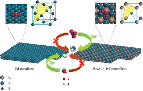
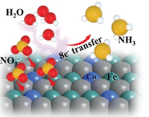
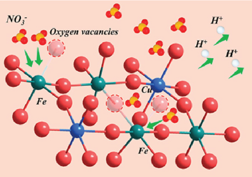
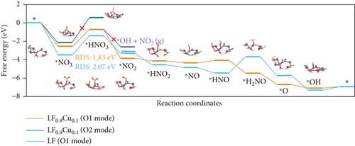
A hydrogel electrode based on a poly(N, N-dimethylacrylamide) network chemically crosslinked with carbazole and thiophene and with a purpurin–coordinate Fe catalyst anchored on the hydrogel [235]. The Fe-modified hydrogel, utilized for reducing nitrate to ammonia, demonstrates efficient selectivity with a high production rate at pH 4.5. The hydrophobicity of polycarbazole on the hydrogel increases under negative bias due to the electric field-induced detachment of the hydrophilic anion. As a consequence, this spurs the hydrogen evolution reaction (HER) due to the internal hydrophobic microenvironment. Additionally, the external hydrophilic hydrogel provides a high density of ions, aiding the mass transfer process. The Fe hydrogel catalyst demonstrates consistent and stable selective NH3 production for over 100 hours [235].
Perovskite oxides (ABO3, where A represents alkaline-earth or rare earth metals and B represents transition metals) are typically prepared using sol–gel or ball milling methods, offering high flexibility for incorporating bimetallic perovskites at the B-sites [236]. The tailoring of octahedral sites allows control over B–O hybridization, inducing oxygen vacancies to modulate catalytic activity [237]. Substituting B-sites influences the surface potential and work function, facilitating electron transmission from the catalyst to the reactant. Perovskite-based materials demonstrate efficient catalytic activity by exposing active sites [238]. The use of submicron or 1D perovskite structures prevents agglomeration, promoting efficient reactant diffusion and electron transport during catalytic activity [239]. Consequently, this design maximizes exposure to intermediates for the adsorption and activation processes. Chu et al. reported that LaFeCuO sub-microfibers, with strong Fe–O hybridization, exhibit a 349 μg h−1 mgcat−1 ammonia yield rate and 48% FE compared to LaFO [15]. The findings indicate that more oxygen vacancies result in a more positive surface potential and a higher ammonia yield rate (Figures 16(b)–16(d)). The positive surface of LFCuO induces nitrate and proton-electron coupling (rate-determining step: ∗NO3 + H+ + e− → ∗HNO3), decreases the energy barrier (LaFCuO: 1.84 eV, LFO: 2.07 eV), and suppresses the HER [15].
Metal–organic frameworks (MOFs) are considered for eNITRR (electrochemical nitrate reduction reaction) due to their abundant active metal sites, porous structure, and the opportunity to tune electronic properties [240, 241]. However, their low electrical conductivity puts them at a disadvantage in terms of catalytic activity. It is auspicious that under electrochemical catalytic conditions, MOFs undergo structural reconstruction or the formation of multiphase species, which can boost catalytic activity [242, 243]. Yang’s group has shown that a Co-based MOF (Co–TPA) transforms into high-valent Co-active sites (CoOOH) to become an electrochemical active catalyst (Co–TPA–E) under electrochemical conditions [244]. The introduction of Cu to the Co–TPA tailors the electronic cloud distribution, enhancing nitrate adsorption and ammonia desorption on the Co sites. Cobalt is also considered an effective doping agent due to its abundant electronic state. Zhang’s group engineered Co doping on defect-engineered (oxygen vacancy) TiO2 nanotubes, which efficiently facilitate electron transfer to nitrate and exhibit high selectivity for ammonia production [245]. In this context, codoping suppresses the desorption of reactant intermediates (∗NO/∗NO2), while defect engineering increases electrical conductivity and charge density, ultimately boosting ammonia production [245]. The Xiaohui group drew inspiration from the biological conversion of nitrate to ammonia through a tandem process, employing a sequential active-site-switching (SASS) mechanism [246]. In this mechanism, two different intermediate species alternate between active sites. Cu–Fe heterophase interface nanoparticles, anchored on TiO2, facilitate the nitrate adsorption on in-plane Fe sites, which then switch toward the Fe–Cu interface for catalysis into ∗NH3. Subsequently, the reaction switches to the in-plane Cu phase, leading to desorption [246]. In situ ATR–SERIES (attenuated total refection Fourier transform infrared spectroscopy) technology is employed to identify key reaction intermediates on NITRR. The electrochemical reduction of nitrate to ammonia is confirmed by the stretching peaks at 1494 cm–1 (N–H stretching/bending mode) and the broadening peak at 3460 cm–1 (Figure 17(a)). Intermediate peaks of ∗NO3, ∗NO2, and electrolyte ∗SO4 species on the electrode are identified at 948, 1241, and 1110 cm–1, respectively. The strongest peak at 1494 cm–1 (∗NH3) on Fe, compared to Cu, indicates that the Cu phase is more favorable for the desorption of ∗NH3 (Figure 17(b)). It is demonstrated that in the electrolyte adsorbs on the in-plane Fe phase, and ∗NO3 species intelligently switch toward the Cu/Fe–TiO2 heterophase interface, where they undergo reduction to ∗NH3 through consecutive protonation and hydrogenation processes (Figure 17(c)). In the final steps, ∗NH3 switches toward the Cu phase, and facile desorption occurs.
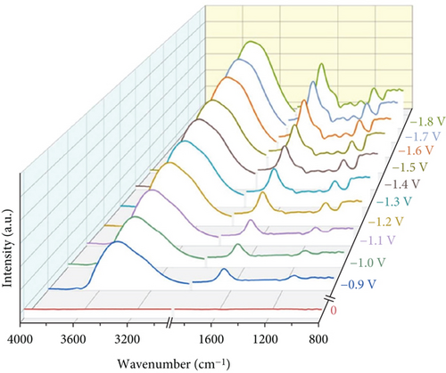
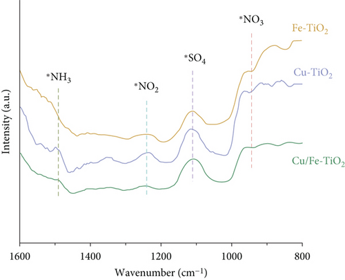
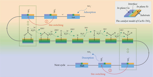
Pd-incorporated Cu-based MOF (CuPd–MOF) precatalysts were employed, leading to an in situ reconstitution into a multiphase heterostructure of Cu/Pd/CuOx at the electrocatalytic operating conditions [242]. The interface among Cu, Pd, and CuOx generates uneven spatial charge distribution. This uneven spatial charge distribution induces interface polarization, causing the transfer of electrons from Pd to Cu, thereby increasing the adsorption of nitrate on electron-deficient Pd sites. Furthermore, it promotes the reduction on the electron-rich Cu sites [242].
Co-doped Fe@Fe2O3 was employed for NITRR, where the Co dopant shifted the Fe d-band center, altering the adsorption energy of intermediates and the free energies of the PDS [247]. The adsorption energy of ∗NO3– in Co-Fe@Fe2O3 is –2.60 eV, stronger than Co (–2.43 eV) and weaker than Fe@Fe2O3 (–2.61 eV). The adsorption strength follows the order Fe@Fe2O3 > Co-Fe@Fe2O3 > Co, indicating that Co-Fe@Fe2O3 possesses moderate strength, favorable for the adsorption and desorption of intermediates, facilitating efficient NITRR. From the Tafel slope, the Co-Fe@Fe2O3 catalyst (70.7 mV dec–1) demonstrates faster NITRR kinetics than Fe@Fe2O3 (87.7 mV dec–1). The electrocatalyst exhibits a nitrate removal capacity of 100.8 mg N gcat–1 h–1, an ammonium selectivity of 99%, an NH3 yield rate of 1505.9 μg h–1 cm–2, and an FE of 85.2% [247]. In another study, Deng et al. synthesized metallic Co nanoarrays (Co–NAs) by reducing Co(OH)2 for NITRR [248]. The intrinsic activity of Co0 is evident due to the intimate contact between active species and the conductive substrate. Co–NAs exhibit a noteworthy ammonia production rate of 104 mmol h–1 cm–2 and a current density of –2.2 A cm–2 at 0.24 V RHE under alkaline conditions. The Tafel slope indicates that Co–NAs facilitate faster kinetics with a slope of 24 mV dec–1 compared to Co (OH)2–NAs, which exhibit a Tafel slope of 197 mV dec–1. Notably, the metallic Co in Co–NAs provides optimized intermediate adsorption compared to pristine Co (OH)2 [248].
Phthalocyanine- (Pc-) based electrocatalysts, characterized by a planar conjugated array in a 2D structure, hold promise for the electrochemical reduction of CO2 and N2, with examples such as CoPc, NiPc, and CuPc. The Rajmohan group employed copper phthalocyanine (CuPc) supported on carbon nanotubes (CNT) for nitrate reduction, achieving an impressive 76% nitrate removal efficiency [249]. Simultaneously, the Li group homogeneously doped nickel phthalocyanine into a carbon nanotube sponge fiber, resulting in outstanding performance with 97.6% nitrate removal, 88.4% ammonia selectivity, and 86.8% FE at a nitrate concentration of 50 mg-N L–1 at –1.2 vs. Ag/AgCl [250]. The Ni–N4 active sites play a crucial role in suppressing the HER, while the reduction of dinitrogen enhances ammonia selectivity and FE. The impressive capacitance (11.7 mF cm–2) and electrochemical durability of NiPc–CNT demonstrate improved nitrate reduction performance.
In another study, the Ghorai group utilized 2D graphene sheets with 1D Mn (II) Pc, producing a pyrrolic-N-coordinated electron-deficient Mn center [251]. This Mn center interacts to generate vital intermediates of the NITRR process. The MnPc/RGO electrocatalyst exhibits an ammonia yield rate of 20316 μg h−1 mgcat−1, an FE of 98.3%, and over 2 days of electrocatalytic activity [251]. Similarly, in another study, the Ghorai group designed hollow materials of FePc rectangular nanotubes for nitrate reduction, achieving 100% FE and a 35067 μg h−1 mgcat−1 ammonia yield rate at –1.5 V vs. RHE [252]. The main active sites for capturing nitrate molecules for NITRR are the Fe centers surrounding the pyridinic N, compared to the HER. Moreover, rectangular nanotubes contain more exposed active sites at the inner and outer surfaces, and the binding strength facilitates selective electrochemical NH3 synthesis. The smaller 0.2 nm hydrodynamic radius nitrate ion can easily enter into the 120 nm width tube, and nitrate residence in the tube is quite large due to the 30–50 μM longer length of the tube. Additionally, FePc is more selective for NITRR due to the stronger exothermic adsorption behavior of NO3 than H [252].
6. Electrolytes
The electrolytes pose a pivotal role in mediating various aspects of the NRR to ammonia. The multifaceted functions of electrolytes in NRR processes encompass a range of electrolyte types. An investigation into Li-based, ionic liquids and aqueous, solid, and organic electrolyte variants reveals their distinct functionalities in facilitating N2 enrichment, proton transfer, and electron transport and anchoring to the catalyst surface.
Advantages associated with aqueous electrolytes, including economic viability, simplicity, and efficient proton exposure and transfer, emerge as crucial factors influencing the protonation steps of NRR. Organic-based or molten hydroxide electrolytes are identified as effective means to reduce proton content, eliminating competitive HER from substances such as methanol, ethylene diamine, and isopropanol. While fluorinated ionic liquids solvate N2, enhancing FE, their impact on NH3 yield and production rate is limited, unsuitable due to their high cost to commercial scale. Additionally, conventional aqueous electrolytes, restricting N2 solubility, are recognized as platforms for the NRR process. Anionic counterparts (Cl–, OH–, SO42–, and ClO4–) in aqueous electrolytes influence the catalyst’s active site for N2 adsorption but cannot serve as carriers of N2 into the medium surrounding the catalyst. Despite their advantages, challenges with electrolytes surface, particularly in the case of organic electrolytes, which often become unstable in the reducing environment of the catholyte. Large amounts of organic solvents deviate from the goal of achieving green NH3 formation efficiency [253, 254].
Li-based electrolytes, specifically LiClO4-containing tetrahydrofuran/ethanol, were utilized for N2 conversion. Ti and Ag working electrodes exhibited considerable catalytic activity, with NH3 outputs measuring 14.1 and 14.5 μmol. Conversely, Al and Pd electrodes demonstrated poor activity due to alloy formation with Li and subsequent passivation. In the electrochemical system, Li accepts electrons under the current and deposits on the electrode surface, subsequently reacting with N2 to form Li3N and follow the catalytic conversion to ammonia and ethanol. Li-mediated facilitated by solvent such as 2-propanol and ethanol, where Li readily reacts with solvents containing active protons. Despite these advancements, Li-mediated electrolytes face challenges, requiring high potentials exceeding 3 V, safety concerns, and the expensive recovery of Li [253–255]. In overcoming these challenges, Biswas et al. proposed and utilized NaBF4 aqueous working electrolyte as an N2 carrier and a full-fledged cocatalyst alongside MnN4 active materials. BF3, with moderate Lewis acidity, formed an adduct with N2, enhancing its solubility in the aqueous electrolyte (Figure 18) [256]. The chemisorbed N2 molecules on the transition metal facilitated the facile polarization of the N≡N bond and its first protonation at a much lower energy barrier. The push–pull effects orchestrated by the NaBF4 aqueous electrolyte overcame the kinetics of the potential-determining steps of NRR. This innovative approach resulted in an NH3 production rate of 2.45 × 10⁻⁹ mol s–1 cm–2 and an ammonia yield rate of 328.59 μg h–1 mgcat–1 at 0.0 V vs. RHE, marking a significant advancement in the field of NRR. This chronological exploration highlights the evolution of electrolytes in NRR processes, from aqueous and organic variants to innovative applications such as NaBF4 aqueous electrolyte, offering promising avenues for enhanced ammonia production efficiency [256].
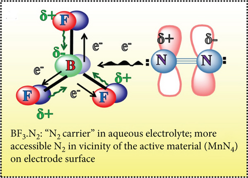
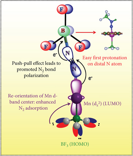
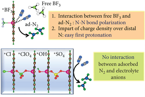
7. Future Research Perspective and Summary
The electrocatalytic production of ammonia emerges as the most effective strategy to address the energy-intensive Haber–Bosch process and reduce nitrogen pollutants in the environment. Achieving higher efficiency in ammonia production through electrocatalysis demands precise control and design of the electrocatalyst (Figure 19).
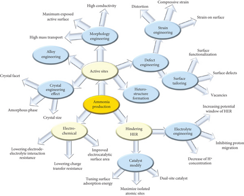
Transition metals, known for their efficacy in nitrogen reduction, face challenges posed by the efficient and competitive hydrogen evolution reaction (HER). A potential solution lies in simultaneously depositing materials with characteristics such as low hydrogen adsorption, oxygen vacancies, or creating local hydrophobic environments. This approach can positively impact the reduction of the competitive energy associated with the HER. However, a careful trade-off strategy is required, considering the weak binding energy of transition metals to nitrogen and their stronger binding to NH3.
Morphological modifications, including specific surface facets such as nanospikes, sharp tips, and thickness adjustments, can influence reaction pathways and electric fields. Maximizing the number of intrinsic operative active sites in the electrocatalyst, achieved through techniques like the exfoliation of few layers or the use of single-metal atoms, enhances performance by increasing atomic utilization efficiency. The consideration of an ordered electrocatalyst structure, as opposed to a disorderly one, is also crucial. Ordered structures, with stronger electron interactions, impact bond lengths, thereby increasing catalytic activity. One-dimensional, high aspect ratio, inherent anisotropy, hollow tube, and nanowire structures could be an effective way to produce efficient electrocatalysts. Additionally, considering the maximum atomic utilization by single-atom catalysts could further be developed, considering ordered intermetallic single-atom alloys dedicated to a higher density of isolated atoms, as an efficient design strategy for new materials. Also, a dual-single-atom strategy to guide specific reaction pathways and counter unwanted reaction intermediates could guide selective ammonia production.
Drawing inspiration from the nitrogenase process, a biomimicking approach to electrocatalyst design involves strategies such as multicoordination, epitaxial growth of oxides on quantum dots, or the creation of core-shell structures. These approaches could offer selective catalytic pathways.
Carbon nanofibers with noble or non-noble metal deposition could provide a local hydrogen source for catalytic processes to counter the HER process. Also, creating hydrogen vacancies on metal hydride-based catalysts using metal foam-based substrates or films could be an alternative material design perspective to counter competitive hydrogen production or increase catalytic hydrogenation processes.
In situ generating stacking faults during electroreduction could be an effective strategy for the development and modification of novel catalysts. Also, in situ partial oxidation electrocatalysts could provide an efficient active electrocatalytic process. Heterojunction strategy modulation of the band gap to Fermi level, modifying electronic properties, could improve catalytic activity.
The corrosive and caustic nature of NH3 (ammonia) requires careful consideration. It is essential to emphasize that the design process should meticulously consider the materials chosen, with a particular focus on their resistance to ammonia (stainless steel, aluminum, magnesium, and titanium). To address this challenge effectively, the focus needs to go beyond merely selecting catalysts; instead, it should extend to meticulous attention to material design. A comprehensive understanding of their resistance properties is vital for the successful design and implementation of effective catalysts. As we move forward, integrating these insights into the development of electrocatalysts will play a pivotal role in advancing the efficiency and sustainability of ammonia production processes.
From a mechanistic standpoint, the competitive hydrogen evolution reaction in electrocatalysis is critically important, necessitating the adsorption of two H∗ species for efficient hydrogen production at adjacent active sites. It is imperative to strategically design the electrocatalyst to maximize isolated active sites, thereby effectively inhibiting the coupling of H∗ species. The adoption of an isolocated single-atom approach is instrumental in reducing H∗ coupling at neighboring catalyst sites. Moreover, the integration of a dual-site catalyst broadens the scaling relationships concerning the adsorption strength of various intermediates. The strategies for suppressing the HER by employing kinetic or thermodynamic regulation could provide promising future perspectives. In kinetic regulation, techniques such as adding alkali metal cations, constructing hydrophobic layers, restricting proton accessibility, or limiting access to both protons and electrons could be utilized. Additionally, thermodynamic regulation methods such as constructing hybrid electrolytes, adjusting pH values, increasing pressure and changing temperature, reducing proton concentrations, and manipulating the equilibrium of the HER represent futuristic approaches to enhance the catalytic process for selective ammonia production. Additionally, the introduction of nitrogen vacancies (VN) into the catalyst structure enhances the activation of N2, providing effective sites for nitrogen reduction. Optimizing the configuration of dual active sites in conjunction with a two-dimensional (2D) nanosheet architecture could significantly improve the utilization efficiency of active sites, potentially leading to advancements in electrocatalytic nitrogen reduction.
A judicious catalyst design principle should focus on suppressing the HER by developing catalysts that retard HER activity. Moreover, the catalytic activity can be finely tuned through a myriad of strategies, including surface modification, crystal facet engineering, structural adjustments, size strain optimization, introduction of defects and vacancies (such as O, N, and S), and engineering techniques. Additionally, heteroatom doping, amorphization, substitution of transition metals, activation of single or dual atoms, incorporation of heteroatoms doping into dual-single-atom structures, tuning of coordination bonds, and manipulation of SACs microenvironments should be considered pivotal materials development principles. These strategies collectively hold the promise of advancing the design of effective catalysts for ammonia production, marking a significant leap in the field of catalysis and materials science.
The production of green ammonia via electrocatalytic processes is assessed using the technology readiness level (TRL) framework, as depicted in Figure 20. In a previous study, the Ghorai research group assessed advancements and utilized a scanning framework to evaluate the TRL relevant to electrocatalytic urea synthesis [257]. This methodology serves as the foundation for scanning the TRL in our current investigation, aimed at electrocatalytic green ammonia production. The TRL framework categorizes technological maturity into nine distinct levels, culminating in level 9, which signifies the achievement of full commercial operation. These levels are further divided into three broad stages: initial research in the laboratory (levels 1–4), pilot-scale development (levels 5–6), and final development leading to commercialization (levels 7-9). Currently, the electrocatalytic process for ammonia production is situated at level 4, indicating preliminary validation in a laboratory setting. To advance this technology through the subsequent TRLs, a meticulous approach in material design is imperative. This approach should be in line with the principles outlined in Figure 19, focusing on the reduction of competitive side reactions, the full and efficient exploitation of atomic-scale catalytic active sites, and the enhancement of scaling relationships among various intermediates, particularly in terms of optimizing adsorption strength. Such strategic developments are essential for transitioning the electrocatalytic production of green ammonia into a viable, commercially ready technology.

Conflicts of Interest
The authors declare no conflict of interest.
Authors’ Contributions
G.A.K.M.R.B. and J.-H.J. were responsible for the conceptualization. G.A.K.M.R.B. was responsible for the methodology. G.A.K.M.R.B. and J.-H.J. were responsible for the validation. G.A.K.M.R.B. wrote the original draft. G.A.K.M.R.B. and J.-H.J. wrote, reviewed, and edited the manuscript. G.A.K.M.R.B. and J.-H.J. were responsible for the resources. G.A.K.M.R.B. and J.-H.J. were responsible for the supervision. J.-H.J. was responsible for the funding acquisition. All authors have read and agreed to the published version of the manuscript.
Acknowledgments
This work was supported by the Korea Institute of Energy Technology Evaluation and Planning (KETEP) grant funded by the Korea government (MOTIE) (2021202080023B, Development and demonstration of thermoelectric power generation system for marine application by waste heat utilization). This work was also supported by the Korea Institute of Energy Technology Evaluation and Planning (KETEP) grant funded by the Korea government (MOTIE) (RS-2023-00243201, Global Talent Development project for Advanced SMR Core Computational Analysis Technology Development).


