Formula of Cylindrical Spring Stiffness for Nonlinear Large Deformation and Its FEM Verification
Abstract
Springs are fundamental components in mechanical systems, crucial for ensuring the safety and functionality of mechanisms. Timoshenko’s stiffness formula accounts for both bending and torsional energy effects, providing accurate results for small deformations. However, when the deformation becomes large, the spring stiffness becomes a nonlinear problem due to the changing inclination angle and radius during deformation. In this study, we derive a formula for the cylindrical spring stiffness under nonlinear large deformation by considering two assumptions: the invariability of the polar angle at any point and spring wire length during deformation. This formula incorporates the effects of inclination and radius changes on the spring wire. We analyze the stiffness of the cylindrical spring with different initial inclinations using the finite element method (FEM). FEM results were compared with those obtained from Timoshenko’s formula, Hiroyuki’s formula, and the derived formula. For small deformations, the FEM results matched well with all three formulas. However, for nonlinear large deformations, the calculated results from Timoshenko’s formula showed a discrepancy of up to 32.58% compared to the FEM results. The modified Hiroyuki formula also exhibited slightly poorer agreement with the FEM results than the formula proposed in this paper. On the other hand, our derived formula demonstrated excellent agreement with the FEM results for nonlinear large deformations. Therefore, our stiffness formula for cylindrical springs is recommended for mechanical engineering spring design applications involving nonlinear large deformations.
1. Introduction
Springs are often used in mechanical systems such as automotive engines and suspension systems [1, 2]. The stiffness, strength, and stability of springs play an important role in the safety of mechanism [3–5]. The springs are often classified as cylindrical spring, leaf spring, and torsion bar spring. However, because of the good performance of the cylindrical spring, the cylindrical spring is widely used in engineering [6, 7]. The spring stiffness of the cylindrical spring is one of the important parameters on the spring properties [8]. In engineering, people use the formula to compute the cylindrical spring stiffness [9], where G is the shear modulus of the spring, d is the diameter of the spring wire, n is the number of coils in the spring, and R0 is the initial radius of the spring. The spring stiffness can be optimized by adjusting these parameters (d, n, R0) [10]. The spring stiffness in this equation includes only the effect of torsional energy on the spring wire.
Researchers often use SolidWorks [28, 29] or Pro/E to establish the model of the spring; import the model into Ansys [27, 30], Abaqus [31], or other finite element software; and calculate the stiffness and strength of the spring by these FEM programs. For the case of small deformation, the spring stiffness is almost invariable during deformation. But the large deformation of the spring belongs to the geometric nonlinear problems [23, 26, 27, 32–34]. Therefore, it is very meaningful to study the change of the cylindrical spring stiffness during the large deformation.
In this paper, the stiffness expression of the cylindrical spring with free rotation (one end fixed, one end free) is given. The structure of this paper is as follows: In Section 2, the two assumptions are given. The geometric parameters of the cylindrical spring are defined. The two assumptions are in good agreement with the FEM results. In Section 3, the nonlinear relation between the load and the spring deformation is established. The formula of the spring stiffness includes the nonlinear effect of spring deformation up to quadratic terms of the deformation h. The torsional and bending deformation energy of the spring wire is given during the deformation. The nonlinear formula of the spring stiffness is obtained by the energy method. To derive the formula of the spring stiffness, we consider the influence of the inclination change and the radius change. In Section 4, we compare the FEM results with those of Formulas (1) and (2) and our Formula (27). Our Formula (27) is reliable and useful to the design and calculation of the cylindrical spring in the case of the nonlinear large deformation.
2. Geometrical Parameters and Their Description of Cylindrical Spring
2.1. Geometrical Description of Cylindrical Spring
2.2. Two Assumptions of Spring on Deformation
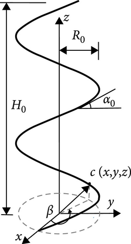
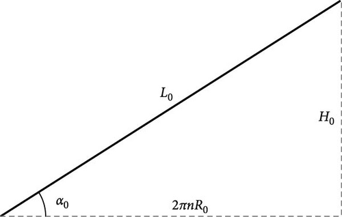
If the central axis of the spring coil always coincides with the z-axis in Figure 1 during the nonlinear large deformation of the spring, the two assumptions are proposed:
Assumption 1. Compared with the torsion and bending deformation energy, the axial deformation energy of the spring wire is very small. Hence, the length is almost invariable during the large deformation, i.e., L ≈ L0.
Assumption 2. It is assumed that the spring is stable during the whole large deformation process and will not destabilize; the polar angle β of any point at the spring wire is invariable during the large deformation; therefore, the number n of the spring coils of at any time is always invariable.
The above two basic assumptions are consistent with empirical evidence and our FEM simulations.
3. Nonlinear Formula of Spring Stiffness for Large Deformation
3.1. Form of Nonlinear Relation Between Load and Deformation on Spring Stiffness
3.2. Torque and Bending Moment of Spring Wire Under Load P
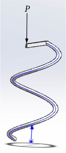
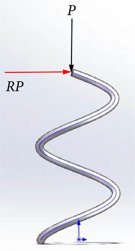
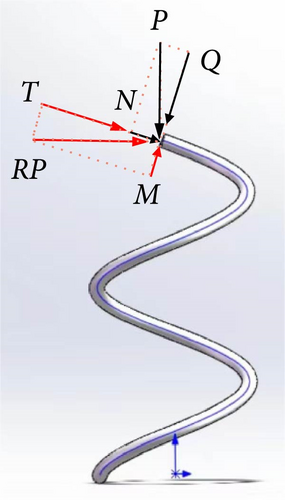
The vertical load P in Figure 2a can be equivalent to the moment RP and the force P acting on the spring wire as shown in Figure 2b. The moment RP in Figure 2b can be decomposed into the torque T and the bending moment M acting on the spring wire as shown in Figure 2c. The principal vector P can be decomposed into the shear force Q and the axial force N acting on the spring wire.
The nonlinear factor η(κ0, Δκ) in Formula (27) is the quadratic polynomial of Δκ. η2 and η3 are related to the initial inclination κ0.
4. Discussion and FEM Simulations of Cylindrical Spring Stiffness for Nonlinear Large Deformation
4.1. Nonlinear Stiffness Formula (27) and Its Reduced Result: Timoshenko Formula for the Small Deformation
4.2. Verification of Experimental Result: Verification of Assumption 1 and Assumption 2
4.2.1. Verification of Assumption 1
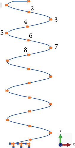
For this verification, we take H0 = 250 mm cylindrical spring in Formula (31). Then the length L0 of the spring wire is 533.447 mm from Formulas (4) and (31) and H0 = 250 mm. The FEM model of the cylindrical spring is shown in Figure 3. We find the maximum axial force FN = (P sinα)max = 31.51 N in the calculation process of the FEM model for the nonlinear large deformation. The length of the spring wire is deformed to by the maximum axial force FN, where is the cross-sectional area of spring wire. The deformation 0.023 mm of the spring length is small compared to the initial length L0 = 533.447 mm. The feasibility of Assumption 1 is verified.
4.2.2. The FEM Verification of Assumption 2
Employing the spring data in Formula (31) with H0 = 250 mm, we establish the FEA model by Abaqus software as shown in Figure 3.
In Figure 3, each end of the coil spring is connected to two wires of high stiffness. The lower wire is fully fixed, while one end of the upper wire is linked to the spring, and the other end applies load P while constraining the displacement of the point in both the x and y directions. This constraint ensures that the load remains centrally located throughout the loading process, thereby preventing eccentric instability. The FEM spring model is meshed by the three-node quadratic spatial beam element. The displacement of the spring is computed utilizing the geometric nonlinear iterative method. Within the FEM simulation, we monitor the changes in the polar angles of the eight specified points as depicted in Figure 3. The computational results indicate that the polar angles of these eight points remain constant throughout the nonlinear large deformation, thereby validating the second assumption’s accuracy.
4.3. Consistence of Computational Results Between Formula (27) and FEM Under Tensional Load
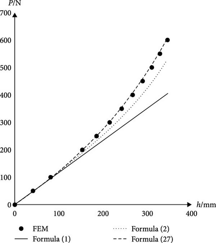
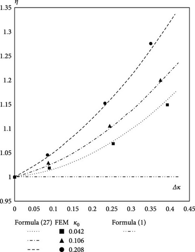
Similar to the results in Figure 5 and Table 1 for κ0 = 0.042, we also compute the stiffness results (KFEMKTimKHiK) of the cylindrical spring based on the FEM, the Timoshenko Formula (1), and our Formula (27) for κ0 = 0.106 and 0.208, respectively. Then we put the computed stiffness results (KFEMKTimK) into η(κ0, Δκ) = 1 + η2Δκ + η3Δκ2 in Formula (27), and we plot the nonlinear factor of the spring stiffness η(κ0, Δκ) as shown in Figure 6.
| κ0 = 0.391 | κ0 = 0.469 | |||||||||
|---|---|---|---|---|---|---|---|---|---|---|
PFEM/ (N) |
h/ mm |
KFEM/ (N/mm) |
KTim/ (N/mm) |
KHi/ (N/mm) |
K/ (N/mm) |
h/ mm |
KFEM/ (N/mm) |
KTim/ (N/mm) |
KHi/ (N/mm) |
K/ (N/mm) |
| 0 | 0 | — | — | — | — | 0 | — | — | — | — |
| −30 | −26.62 | 1.13 | 1.12 | 1.29 | 1.08 | −28.11 | 1.07 | 1.09 | 1.36 | 1.03 |
| −50 | −46.77 | 0.99 | 1.12 | 1.26 | 1.01 | −49.60 | 0.93 | 1.09 | 1.32 | 0.97 |
| −70 | −67.13 | 0.98 | 1.12 | 1.24 | 0.98 | −71.24 | 0.92 | 1.09 | 1.29 | 0.92 |
| −90 | −88.43 | 0.94 | 1.12 | 1.22 | 0.96 | −93.55 | 0.90 | 1.09 | 1.26 | 0.90 |
| −110 | −109.71 | 0.93 | 1.12 | 1.20 | 0.95 | −116.51 | 0.87 | 1.09 | 1.23 | 0.88 |
In Figure 6, Δκ has a great influence on the nonlinear factor η(κ0, Δκ) of the spring stiffness. Formula (27) agrees with the results of the FEM. The results in Figure 6 show that Formula (27) is important and necessary for the large deformation computation of the cylindrical spring.
4.4. Consistence of Computational Results Between Formula (27) and FEM Under Compression Load
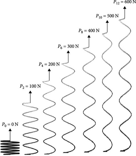
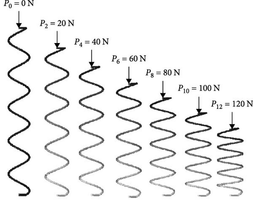
In Figure 7, we present the deformation processes of the cylindrical spring (κ0 = 0.469) under compression load. Then we put the computed stiffness results (KFEM KTim K) into η(κ0, Δκ) = 1 + η2Δκ + η3Δκ2 in Formula (27), and we plot the nonlinear factor of the spring stiffness η(κ0, Δκ) as shown in Figure 8.
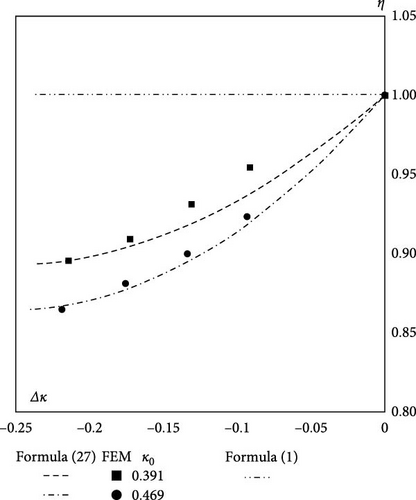
In Figure 8, Δκ also has a great influence on the nonlinear factor η(κ0, Δκ) of the spring stiffness under compression conditions. At the same time, it can be found that the greater the κ0 of spring, the more obvious the nonlinear effect of spring stiffness. Formula (27) agrees with the results of the FEM. The results in Figure 8 show again that Formula (27) is important and necessary for the large deformation computation of the cylindrical spring.
Comparing Figures 8 and 6, we can find that the finite element results for the tensile condition are in better agreement with the theoretical results than the compressive condition with the theoretical results. This is due to the fact that the spring does not destabilize and bend laterally in tension. During compression, even if it is ensured that the load always acts on the positive center of the spring, it is still difficult to prevent a little transverse bending of the spring during large deformations of the spring, which can lead to slight errors.
5. Conclusion
This study delves into the formulation of cylindrical spring stiffness under nonlinear large deformations and its verification through FEM. The proposed Formula (27) takes into account the combined effect of torsional and bending deformation energies, as well as the effect of pitch angle and radius variations on stiffness, which provides a comprehensive approach to stiffness calculations in nonlinear situations.
By verifying two fundamental assumptions and conducting FEM simulations, we compared the results obtained from Timoshenko’s formula, Hiroyuki’s formula, and our derived formula. For small deformations, all three formulas showed good agreement with the FEM results. While the modified Hiroyuki formula also exhibited some discrepancies, our derived formula demonstrated excellent alignment with the FEM results for nonlinear large deformations. Comparative analyses with existing formulas reveal significant discrepancies under large deformations, emphasizing the necessity of accurate stiffness formulations for practical engineering applications. FEM simulations under tensional and compressive loads demonstrate the efficacy of Formula (27) in capturing the nonlinear behavior of cylindrical springs. The formula’s reliability and consistency with FEM results highlight its suitability for designing and analyzing cylindrical springs experiencing nonlinear large deformations in mechanical engineering applications.
In conclusion, the derived Formula (27) offers a robust and accurate tool for engineers to predict and optimize cylindrical spring properties under nonlinear large deformations, facilitating enhanced design efficiency and performance in mechanical systems.
Disclosure
The authors have no relevant financial or nonfinancial interests to disclose.
Conflicts of Interest
The authors declare no conflicts of interest.
Author Contributions
Conceptualization, Z.H.; software, C.R. and R.Z.; formal analysis, T.Z. and F.X.; investigation, M.H. and T.Z.; resources, Z.H.; data curation, F.X. and C.R.; writing, original draft preparation, H.Y., and Z.H.; writing, review and editing, H.Y. and T.Z.; project administration, H.Y. All authors have read and agreed to the published version of the manuscript.
Funding
This work was supported by the Jiangxi Provincial Natural Science Foundation (Award No. 20224BAB214072) and the Jiangxi Province Education Science “14th Five-Year Plan” Project (Award No. 22QN007).
Open Research
Data Availability Statement
The data of this study are available from the corresponding author upon request.


