Reconfigurable Antennas for Wireless Communication: Design Mechanism, State of the Art, Challenges, and Future Perspectives
Abstract
The rapid development of wireless technology has heightened the requirement for antenna performance. Traditional antennas, characterized by their static performance, are no longer sufficient to accommodate the dynamic requirements of modern wireless systems. The advent of reconfigurable antennas has opened new horizons for unleashing the full potential of wireless communication systems. These antennas are versatile and can switch various performance modes in a simple yet ingenious structure. Based on the cutting-edge research, this paper deeply explores their core design principles, the latest breakthroughs, and the ingenious methods. Through an in-depth analysis of a multitude of reconfigurable antenna design cases, existing design methods are categorized into four categories: electronic and optical switches, structural physical change, smart materials, and bistable composites. Each category is subjected to a meticulous dissection, revealing the underlying design mechanisms, highlighting innovativeness, and discussing both the strengths and limitations. Furthermore, by conducting a comprehensive comparative analysis, this paper concludes the forthcoming challenges and prospective trajectories for this research domain. Therefore, this paper can serve as a valuable reference for researchers seeking to deepen their understanding and application of various reconfiguration methods in the design of reconfigurable antennas, guiding them toward the forefront of antenna technology innovation.
1. Introduction
In today’s digital communication era, the rapid development of wireless communication technology is leading the wave of technological innovation. As a key component of wireless communication systems, the ongoing evolution of antenna technology profoundly influences the entire communication landscape [1]. With the continual enhancement of communication networks and the extensive integration of intelligent devices, antenna technology faces stronger demands for the flexibility and adaptability. Although traditional antennas have shown effectiveness in many applications due to their static characteristics, their fixed geometric shapes and static operating parameters limit their ability to adapt to dynamic communication environments [2]. These antennas often struggle to encounter challenges in meeting the diverse requirements of modern wireless systems, including different frequency bands, fluctuating propagation conditions, and variable signal demands [3]. Consequently, there is a growing recognition of the limitations of traditional antennas, prompting an urgent need for more flexible and adaptable alternatives. In this context, reconfigurable antennas emerge as a promising solution. Compared to traditional antennas, reconfigurable antennas possess the capability to dynamically adjust their operating parameters in response to changing environmental conditions and system requirements, including frequency, polarization, and radiation pattern. This inherent adaptability enables reconfigurable antennas to exhibit excellent performance in various operational scenarios, thereby enhancing the efficiency, reliability, and versatility of wireless communication systems [4].
Recently, the field of reconfigurable antennas has become a thriving area of research and development, with significant advances in the design and implementation of reconfigurable antenna solutions. The design process for reconfigurable antennas requires the utilization of multidimensional approaches, which include various methods and technologies tailored to meet specific application requirements [5]. Electrical switch technology is currently the mainstream design approach, which integrates components capable of circuit switching (such as PIN diodes [6], varactor diodes [7], micro–electro-mechanical systems (MEMSs) [8], and optical switch [9]) to achieve dynamic control of antenna parameters (such as operating frequency band, radiation pattern, and polarization). In the design of reconfigurable antennas, these electrical components are used to connect or disconnect antenna elements, redistributing the antenna surface currents to achieve the desired performance reconfiguration. The implementation of reconfigurable antennas with electrical switches is easy and has received significant attention in research. Palsokar and Lahudkar Anuradha A. Palsokar et al. in 2022 [10] used a single PIN diode switch to design a frequency and pattern reconfigurable rectangular patch antenna. This innovative antenna is capable of resonating at frequencies of 2.47, 3.8, and 5.36 GHz and changes its radiation by manipulating the state of the PIN diode. A noteworthy aspect of its design is the utilization of a single PIN diode switch, which significantly simplifies the complexity of the necessary bias network. Different from PIN diodes, the varactor diodes mainly change their capacitance value by adjusting the bias voltage to achieve tuning control of the antenna. Row and Chen in 2022 [11] proposed a frequency reconfigurable antenna by placing two varactors between the radiating patch and the ground plane. By adjusting the bias voltage of varactors, the operating frequency of the antenna can be tuned from 3.3 to 4.2 GHz. The incorporation of the varactors enables the antennas to have a wider tuning range than ones based on PIN diodes. The MEMS switch is a microelectromechanical switch comprised of actuators, sensors, and mechanical elements on the substrate using an IC process sequence [12]. It has many advantages over other switching diodes such as low insertion loss and power consumption, and high reliability [13]. In 2007, Kingsley et al. [14] designed a CPW-fed gasket monopole antenna, which adopted a three-order iterative Sierpinski antenna to realize frequency reconfiguration by controlling the different MEMS switch states. It is mentioned that the proposed antenna does not use any additional bias circuit to actuate the switches, and the antenna has excellent radiation characteristics of four main resonant frequencies, thereby simplifying the antenna structure. However, the switching speed of MEMS is 1–200 seconds, which may be insufficient for some applications [15]. In addition, the optical switch is composed of semiconductor materials and uses bias lines instead of metallic wires [16]. The reconfigurable antennas with optical switches are often used in some special scenarios requiring the coefficient light–like infrared light [17]. However, optical switches are bulky, which means that integrating them into the antennas is a challenge.
Another technique for reconfigurable antennas is based on the change in the structure of the antenna such as origamis, microfluidics, and components with mechanical movement. These antennas do not require a bias network, light, and electronics and have high power handling capability and lower losses [18]. The origami antennas can be fabricated quickly since they simply use folding paper sheets as the antenna substrates and copper as the conductor [19]. Yao et al. in 2015 [20] designed a Nojima antenna with the capability to reconfigurable frequency and pattern. This antenna can resonate at 1.61 GHz in the folded state with a directional radiation pattern and 0.66 GHz in the unfolded state with an omnidirectional pattern. Both the microfluidics and mechanical movement are based on the change of antenna parts. So et al. in 2009 [21] proposed a frequency reconfigurable antenna by varying the length of the dipole made of eutectic gallium–indium (EGaIn) alloy. Yang et al. in 2017 [22] used the micromotor beneath each element to rotate the multiple concentric resonators to achieve frequency reconfiguration.
With the rapid development of advanced materials such as liquid dielectric [23], graphene [24], and shape memory alloy (SMA) [25], the design flexibility of reconfigurable antennas has been improved. These materials can change their permittivity or permeability under different external excitations, such as the liquid crystals under voltage. Ren et al. in 2020 [26] designed a pattern and polarization reconfigurable antenna consisting of a central dielectric resonator antenna and two parasitic dielectric resonator antennas. By controlling the flow of liquid, the parasitic dielectric resonator antenna can be changed to produce different patterns. Graphene is often used to design the THz reconfigurable antennas due to its inherent material propriety. Based on a single-layer graphene, Huang et al. in 2012 [27] proposed a beam reconfigurable antenna for the THz application. By loading different voltages for the graphene, the radiation can vary in a range of ±30° as demonstrated by the simulated results. The application of SMA in the area of reconfigurable antennas is drawing more attention. Sumana and Florence [28] proposed a simple realization method for a pattern reconfigurable antenna structure based on the SMA in 2020. The proposed antenna has two SMA rectangular patches (Patch 1 and Patch 2). By exciting Patch 1 through resistive heating, the antenna generates a tilted beam at an angle of 330°, and similarly for Patch 2 at an angle of 30°, thus realizing pattern reconfigurability. Different from these materials, bistable composite not only has the advantages of both the mechanical reconfigurable technology and the advanced materials but also can keep their stable state without any continuous energy input. The bistable composite often serves as the substrate of the antenna. In 2023, Huang et al. [29] first proposed an integrated solution to design bistable antennas with reconfigurable performance and light-responsive behavior. This antenna included a radiation layer with conductivity and bistable substrate. The effects of the radiation layer material and substrate layer parameters on antenna performance were studied. The achievement of its performance reconfiguration was generated by the snapping between State I and II when the illumination stimulus was given.
However, until now, there have been a few books and review papers providing a comprehensive overview and comparison of reconfigurable antennas. They mainly studied rigid antennas [30], flexible antennas [31], liquid dielectric antennas [32], microfluidic antennas [33], and other types of antennas [34–36]. The design mechanism of reconfigurable antennas has not been studied systematically. Therefore, this paper provides a comprehensive overview and analysis of design methods for reconfigurable antennas, revealing the main advancements and existing challenges in the current research. Through comparison and evaluation of different design methods, it is evident that each approach has its unique advantages and limitations, which needs to be further improved and optimized. Future research efforts can focus on developing the compound reconfigurable antennas and combining two or more methods to meet increasingly complex communication requirements and application scenarios. The framework of this review is shown as follows: the classification of reconfigurable antennas based on the structure and functional components used to realize antenna performance reconfiguration is shown in Section 2. A comparative survey of these four categories is discussed from their design mechanism, design highlights, advantages, and disadvantages in Sections 3–6, respectively. Furthermore, Section 7 points out the challenges and the future perspectives. Lastly, conclusions are drawn in Section 8.
2. The Classification of Reconfigurable Antennas
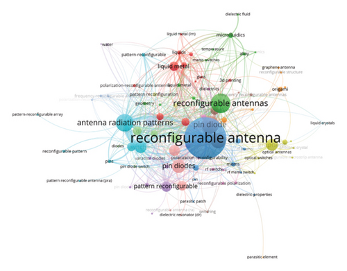
Over the past 5 years, 4535 publications including research papers, proceeding papers, and review articles were enrolled in the Web of Science Core Collection database. The keywords that appear more than five times are chosen and drawn as shown in Figure 1. The more the keyword appears, the larger the junction size is. Designing reconfigurable antennas has been a research hotspot for the last 5 years, as evidenced by the strong cooccurrences identified between antenna performance reconfiguration and numerous design technologies. As can be seen from Figure 1, the research of reconfigurable antennas mainly involves frequency reconfiguration, pattern reconfiguration, polarization reconfiguration, and compound reconfiguration. Among them, the compound reconfiguration refers to the antenna having two or three performance reconfigurations of frequency, pattern, and polarization. The mainstream design technology is to adjust the shape, size, slot size, and short-circuit structures of the antenna radiation part by introducing a switch to achieve frequency reconfiguration, change the current distribution to achieve direction pattern reconfiguration, or adjust the feed network to achieve polarization reconfiguration. In addition, changing the spatial position of the radiating structure is a useful technology, such as loading the micromotor or using origami structures. Recently, the use of smart materials has become a new trend in the design of reconfigurable antennas, such as liquid dielectrics, graphene, and SMAs, which can change the dielectric or geometric properties of the antenna by changing their physical or chemical characteristics, thus achieving the desired reconfiguration of antenna performance.
According to the structure and functional components used to realize antenna performance reconfiguration, the various reconfigurable antennas are divided into four classifications shown in Figure 2, namely, the electrical and optical switches, the structure physical change, the smart materials, and the bistable composite. The electrical and optical switches’ category indicates that the antenna performance reconfiguration is achieved by the electrical switches (such as PIN diodes [37], varactors [38], and MEMS [39]) or optical switches [40], which can switch antenna circuit characteristics by integrating them into the antenna structure. The structure physical change category refers to the antenna performance reconfiguration achieved through the physical changes, such as deformation, rotation, or movement of the antenna structure. For example, origami [41], microfluidics [42], and micromotor [43] can alter the geometry of an antenna by deforming, rotating, or moving its components. Smart materials’ category refers to the performance reconfiguration obtained by introducing the novel material that can change the dielectric constant or geometry of the antenna, such as liquid dielectric [44], liquid crystal [45], graphene [46], and SMA [47]. Bistable composite category refers to using bistable composite as the antenna components to achieve the performance reconfiguration, which is achieved by switching two stable configurations [48]. Moreover, the two stable configurations can be maintained even in the absence of a constant energy supply. Notably, the first antenna based on the bistable structure was reported in 2012 [49], yet a comprehensive review including this subject has been still absent to date. Therefore, the design methods of reconfigurable antennas including the bistable composite will be summarized and studied in the following sections, according to the classification in Figure 2.

3. Reconfigurable Antennas Based on Electrical and Optical Switches
Electrical and optical switches are employed to design reconfigurable antennas by changing their circuit characteristics, including the interconnecting of adjacent elements of the antenna, modifying the feeding networks, or varying the length of the slots. The most commonly used electrical switches are PIN diodes, varactors, and MEMS, almost all of which require the bias circuit. Different from electrical switches, optical switches can use doped silicon (such as photoconductive switches) to respond to external light excitation.
3.1. Reconfigurable Antennas Based on PIN Diodes
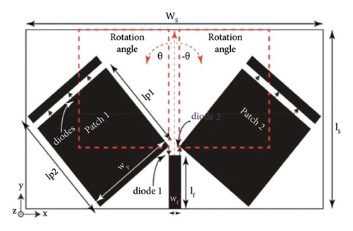
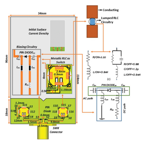
Integrating PIN diodes into the antenna structure is one of the most commonly used methods for changing circuit characteristics. In the RF circuit, PIN diodes act as a variable resistor with ON and OFF states [50–52]. For both states, PIN diodes have an inductance in the equivalent circuit [53]. The ON state includes low resistance, and the OFF state includes a parallel combination of resistance and capacitance [54]. Nowadays, numerous studies have used this method to design various reconfigurable antennas, and this review chooses some typical antennas shown in Figure 3 to analyze the reconfigurable mechanism.
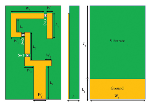
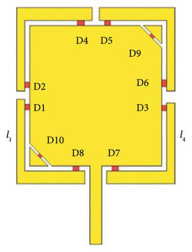

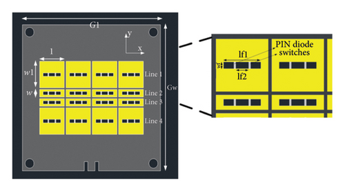
For the design of the reconfigurable antenna based on PIN diodes, the ON state in the PIN diode is modeled as a series resistance–inductance (RL) component to behave as a short circuit, which allows the current to flow along the radiator. In contrast to the ON state, the OFF state in the PIN diode model is modeled as a parallel resistance–inductance–capacitance (RLC) component to exhibit an open circuit, which cannot allow the current flow along the radiator. To simplify the model, the above switch states of open circuit and short circuit behavior are usually realized as lumped RLC boundaries. Firstly, the PIN diodes can be used to change the length and the surface circuit of the proposed antennas. To study the performance reconfiguration of the hexa-band antenna shown in Figure 3(a), Shah et al. in 2019 [55] integrated the three PIN diodes into the hexa-band antenna to change the effective resonant lengths of the radiation structure by controlling the states of PIN diodes. This antenna operated at two single-band modes (3.5 and 4.8 GHz) and two dual-band modes (2.10, 4.15, and 2.4, 5.2 GHz). When Sw1, Sw2, and Sw3 were all turned on, the antenna operated at a dual-band mode (2.10 and 4.15 GHz). When Sw1 and Sw2 were turned on but Sw3 was turned off, the antenna changed to the other dual-band mode (2.4 and 5.2 GHz). When Sw1 was turned on but Sw2 and Sw3 were turned off, the antenna changed to a single-band mode (3.5 GHz). When Sw1, Sw2, and Sw3 were all turned off, the antenna changed to the other single-band mode (4.8 GHz). However, the above reconfigurable characteristics were simulated as resistors only, without considering the capacitance and inductance values. George and Fang in 2020 [56] studied that the PIN diodes were used to change the antenna surface circuit to achieve the desired reconfiguration. A 40 × 40 × 2.5-mm3 antenna with frequency and polarization reconfiguration is shown in Figure 3(b) with 10 PIN diodes, and their ON and OFF states were modeled as the capacitance and Ohmic resistance. Its polarization reconfiguration was achieved by the PIN diodes located at the trimmed opposite corners of the rectangular patch, and the L-shaped radiating elements were introduced to realize the frequency reconfiguration. Specifically, the above eight PIN diodes (D1, D2, D3, D4, D5, D6, D7, and D8) around the rectangle patch were used for frequency reconfiguration operating at 1.6, 2.4, and 2.5 GHz independently, and other two PIN diodes (D9 and D10) located switchable truncated corners of the rectangle patch antenna switched from linear polarization (LP) to circular polarization. However, the antenna performance corresponding to all combined states of these eight diodes is not fully discussed, which means that there may be redundancy in the number of diodes.
In addition to altering effective resonant lengths in [55] and surface current distribution in [56] of the radiation structure, PIN diodes can also change the antenna geometry in [57]. Piazza et al. in 2009 [57] designed a circular patch MIMO antenna with polarization and pattern reconfigurability, as depicted in Figure 3(c). Fourteen PIN diodes were placed radially on the antenna and divided into two groups (Switch D1 and Switch D2) to dynamically change the radius of the circular patch by controlling their bias state, thus exciting the radiation with different shapes and polarization. The polarization reconfiguration was obtained by the ON and OFF states of four PIN diodes to connect or disconnect perturbation portions from the inner circular patch. This antenna had three polarization configurations, involving one elliptical polarization and two LPs. Furthermore, the realization of pattern reconfiguration was the combination of PIN diode states with port excitation states, and three highly uncorrelated radiation patterns were excited at each port with the help of PIN diode states. However, there was a lack of discussion on determining the number of switches and dividing them into two groups.
Moreover, integrating the PIN diodes into the feed structure is also a common reconfigurable antenna design method. Khan et al. in 2020 [58] proposed a pattern and frequency reconfigurable antenna with two patch elements, whose structure was depicted in Figure 3(d). With the help of PIN diodes, the antenna used one feed line to excite the two patch elements located at any angle concerning each other. Specifically, biasing PIN diode 1 achieved the pattern reconfiguration of 30°, whereas exciting PIN diode 2 made its pattern reconfiguration up to −30°, without compromising on the gain of the radiating elements. In addition, to achieve frequency reconfiguration, two small radiating patches were added to the top of the large radiating patches. The patches resonated from 3.3 to 2.43 GHz when PIN diodes were biased between the small and big radiating parts. However, it is not discussed how to determine the relationship between the patch rotation angle and the antenna pattern reconfiguration.
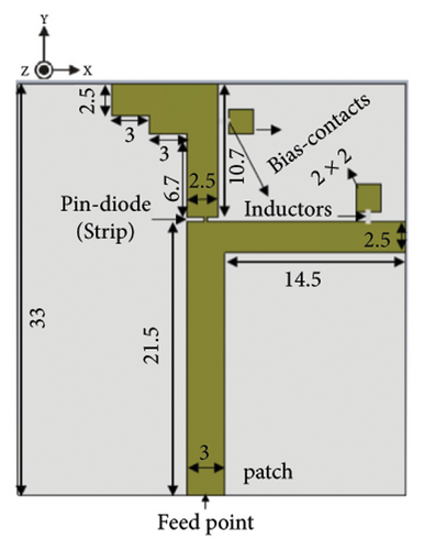
Finally, PIN diodes can also cowork with other electronic elements such as inductors or metasurface. Jhanjhariya et al. in 2019 [59] proposed a dual-band polarization reconfigurable patch antenna with the help of PIN diodes and two surface mount inductors. As shown in Figure 3(e), the prototype antenna consisted of two orthogonal arms as a patch, an inclined slotted asymmetric pentagonal-shaped ground plane, and a PIN diode with a bias circuit. To achieve polarization reconfiguration, a PIN diode was placed across the vertical arm and feed line of the patch, thus changing the length of two orthogonal arms with the help of two inductors placed in series with each DC bias feed line terminals. The polarization characteristics were changed by the PIN diodes state, that is, the ON state made the proposed antenna exhibit a dual-band circular polarization, whereas only a signal band LP is allowed in the OFF state. However, there is less discussion on bias circuit design. A metasurface is a kind of two-dimensional metamaterial, which can produce relatively special electromagnetic properties through artificially fabricated metal structural units and arrangements of cell structures. Chen and Ning in 2020 [60] introduced the metasurface and PIN diodes to design the pattern and polarization reconfigurable antenna, as shown in Figure 3(f). This antenna was composed of a feeding line on the bottom layer, a cross slot on the middle ground layer, and the metasurface on the top layer. Pattern reconfigurations were achieved by changing the states of PIN diodes on the metasurface and the ground plane. These PIN diodes generated three patterns in the operating band from 5.12 to 5.20 GHz, and one of them also realized the polarization reconfiguration by switching between the left-handed circular polarization (LHCP) and RHCP along the Z-axis. The reconfigurable antennas based on PIN diodes have already had a fair development. However, the types of PIN diodes and how to determine its proper location are not discussed.
Table 1 projects the details of various research papers that contribute exclusively to the design of reconfigurable antennas with PIN diodes. It can be inferred from Table 1 that most of the works have integrated PIN diodes into a common antenna configuration and simulated as an RLC component to enable antenna performance reconfiguration. The reconfigurable mechanism is that PIN diodes can change the efficient length of radiation patches, redistribute the surface current of radiation patches, reshape the antenna geometry, cowork with other electrical elements, or connect with metasurface. However, in addition to the number of PIN diodes and their placement, the RF bias network, even the expensive and complicated DC bias circuit must be built up to improve the reliability of PIN diodes. Moreover, the influence of nonlinear harmonic parameters of PIN diodes is also a key issue to be considered. In response to this issue, some strategies have been employed to mitigate some potential challenges such as signal loss, interference, or increased manufacturing costs. Fartookzadeh and Mohseni Armaki in [61] introduced a serial symmetric feeding network with three outputs in their design to enhance the reconfigurability of the antenna and reduce signal interference. Guiping et al. in [62] utilized parasitic elements with PIN diodes and differential feeding ports to achieve dual-polarized four-beam reconfigurable radiation patterns, which help to reduce signal interference and improve the antenna adaptability. Liqiang et al. in [63] incorporated PIN diodes into the feeding path as switches to realize polarization reconfiguration of the antenna while maintaining the simplicity of the antenna design. Li et al. [64] mentioned the design of a compact directional pattern reconfigurable four-element slot antenna, which not only meets the frequency band requirements for wireless communication but also has the characteristics of small size and low manufacturing cost, helping to balance reconfigurability and cost-effectiveness.
| Reference | Type of antenna | Antenna size (length × width × height) ( mm3 ) | Number of PIN diodes | Type of reconfiguration | Design highlights | Advantages | Limitations |
|---|---|---|---|---|---|---|---|
| [55] | Hexa-band antenna | 16 × 40.5 × 1.6 | 3 | Frequency reconfigurable antenna | Change the effective resonant lengths | Compact geometry, high efficiency, and good impedance | Without considering the capacitance and inductance values |
| [56] | Rectangular patch and L-shaped radiating elements | 40 × 40 × 2.5 | 8 | Frequency and polarization reconfigurable antenna | Change the antenna surface circuit | Simple structure, compact size, and good agreement between simulated and measured results | Without full consideration of the antenna performance corresponding to all combined states of eight diodes |
| [57] | A circular patch antenna | R (25.3) × 1.524 | 14 | Polarization and pattern reconfigurable antenna | Change the antenna geometry | Good polarization, high gains, and good radiation patterns | Without discussion on determining the number of PIN diodes and dividing the principle of two groups |
| [58] | Rectangular patch and Connor feed line | 58 × 100 × 1.524 | 8 | Frequency and pattern reconfigurable antenna | Integrating the PIN diodes into the feed structure | Good impedance and high gains | Without discussion of the rotational angle and the antenna pattern reconfiguration |
| [59] | Dual-band patch antenna | 31 × 33 × 1.6 | 1 | Polarization reconfigurable antenna | Cowork with inductors | Good impedance bandwidth and high gain | Less discussion on the bias circuit design |
| [60] | Multilayer antenna | 78 × 78 × 2.37 | 3 | Polarization and pattern reconfigurable antenna | Cowork with metasurface | Good agreement between the simulated and measured results, continuous frequency band, and compact size | Without the type of PIN switches and the discussion of their proper location |
3.2. Reconfigurable Antennas Based on Varactor Diodes
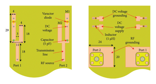
In contrast to PIN diodes, varactor diodes can continuously adjust the capacitance values by changing their reverse bias voltages [65–67]. In antenna design, the varactor diodes are also usually modeled as RLC series lumped components in antenna design [68–70]. Tuning their capacitance value can alter the circuit current value to achieve precise tuning of antennas, which are conductive to the designing reconfigurable antennas [71–75]. Figure 4 shows some typical reconfigurable antennas based on varactor diodes.
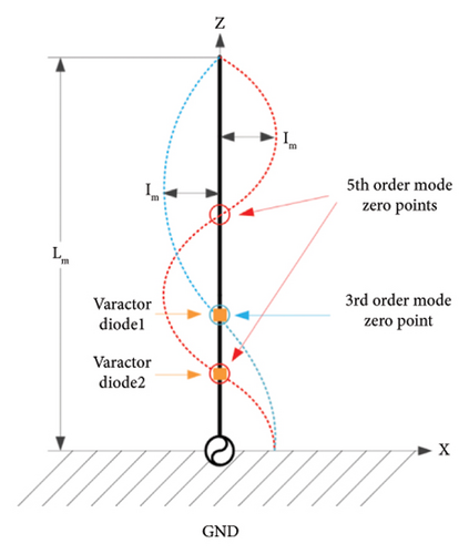

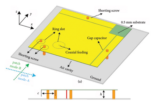
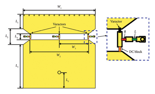
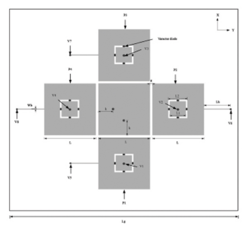
Due to the variable capacitance, the position of varactor diodes often needs to be carefully considered. Luo et al. in 2022 [76], respectively, placed two varactor diodes at the zero point of the third-order mode current distribution and one of the zero points of the fifth-order mode current distribution to control the antenna resonant frequency, as shown in Figure 4(a). By adjusting the reverse bias voltage (0–20 V) of the two varactor diodes individually, the two frequency bands were controlled independently while maintaining a stable radiation pattern. However, the bias circuits were not discussed. In addition to the location of varactor diodes, a suitable feeding network was required to achieve the desired antenna performance reconfiguration. Babakhani and Sharma in 2015 [77] proposed a wideband frequency tunable concentric circular microstrip patch antenna with simultaneous polarization reconfiguration. Although the antenna geometry structure was very similar to that of [57], the electric control elements and bias components shown in Figure 4(b) were different. Four varactor diodes were placed into a very narrow gap to separate the concentric circular rings. By changing the capacitance value of the varactor diodes, the antenna operating frequency varied from 1.17 to 1.58 GHz. Each set of diodes worked together to achieve horizontal and vertical polarization, while it needed to work together with feed ports with a ±90° time phase difference to achieve LHCP and RHCP. However, its feed network was complex. Han et al. in 2024 [78] proposed a miniaturized circularly polarized capacitance-loaded patch antenna with a simple structure and frequency reconfigurability, as shown in Figure 4(c). Unlike the conventional half-wavelength patch antenna, this antenna has a cavity-like structure and does not require a large ground plane. The antenna size is significantly reduced using capacitive loading, and frequency reconfigurability is achieved by introducing two varactor diodes to tune the quadrature radiation gap. However, the miniaturized design brings about a trade-off in terms of bandwidth or gain.
Moreover, the number of varactor diodes should be mentioned. Specifically, fewer varactor diodes will lead to high cross-polarization, while more varactor diodes will bring up a more complicated antenna structure. Dang et al. in 2023 [79] proposed three tuning range extension strategies for varactor-based frequency-reconfigurable planar patch including co-optimization of antenna dimensions and varactor properties, utilization of multiple radiation modes, and reduction of parasitic capacitance. As shown in Figure 4(d), this antenna frequency tuning range was further expanded. However, there are less discussion on the feasibility and cost effectiveness of these tuning range extension strategies in practical manufacturing and applications.
Finally, the varactor diodes can be used to connect the parasitic element, feed port, and ground. Khairnar et al. in 2021 [80] proposed a patch parasitic antenna with independent directional pattern, beamwidth, and polarization reconfigurability. The antenna consisted of a dual-coaxial fed driving element surrounded by four varactor diodes loaded with parasitic elements, as shown in Figure 4(e). Varying the varactor diodes can establish the mutual coupling between the active and size-tunable parasitic element size-tuning ability, which helps achieve the pattern and beamwidth reconfiguration. Moreover, the polarization reconfiguration (two orthogonal LP (left-hand vertical polarization and left-hand horizontal polarization) and circular polarization (LHCP and RHCP) states) was realized by using a feeding network composed of 3-dB quadrature hybrid coupler and RF switches. In the LP mode, the main beam of the antenna can vary from 0° to 11°, 32°, 40°, and ±90°. In circular polarization mode, the radiation direction can vary from ±0°, ±45°, and ±90°. However, its feeding network was very complex. Padmanabhan et al. Azremi Abdullah Al-Hadi et al. in 2021 [81] integrated the varactor diodes and DC bias circuit into the monopole branches to design the dual monopole frequency reconfigurable antenna shown in Figure 4(f). By changing the capacitor value of varactor diodes, a dual-tunable resonant frequency was generated in low (1690–2200 MHz) and high (4400–5400 MHz) frequency bands. On the other hand, the fixed band (2400 MHz) and the −10 dB bandwidth (450 MHz) were implemented by another monopole branch without varactor diodes. However, the introduction of varactor diodes adds the complexity of designing antenna.
Table 2 shows the recent research works on reconfigurable antennas based on varactor diodes. As shown in Table 2, it is observed that varactor diodes are mainly utilized to design frequency reconfigurable antennas due to their capability of continuously adjusting capacitance by changing their reverse bias voltages. Other types of performance reconfiguration should combine the advantages of varactor diodes, electronic elements, and antenna geometry. Moreover, in addition to changing the circuit state of PIN diodes, varactor diodes can also control the radiation current magnitude. To design reconfigurable antennas, the location, number of varactor diodes, and the connecting relationship between other parts of antennas should be elaborately designed. It is mentioned that the complexity of the feed network and bias circuit will increase with the change in their location and number. Recently, a number of optimizations and guidelines have been proposed to effectively address these design challenges. The introduction of intelligent optimization algorithms can quickly determine the switch state or position and other information, improving design efficiency and reducing the cost. Ouedraogo et al. in 2021 [82] used an efficient search algorithm to determine appropriate switch configurations, making the proposed antenna to operate at a certain frequency, or to achieve frequency-scanned with maintenance of the beam at a fixed angle. Moreover, parasitic capacitance also affects the tuning efficiency of varactor diodes. Therefore, reducing parasitic capacitance can improve the sensitivity and range of frequency tuning [79]. Moreover, based on the calibration of the feeding network and the actual measured radiation patterns, unexpected distortion of patterns such as an inaccurate beam direction caused by material and fabrication tolerance can be corrected [83].
| Reference | Type of antenna | Antenna size (length × width × height) ( mm3 ) | Number of varactor diodes | Type of reconfiguration | Design highlights | Advantages | Limitations |
|---|---|---|---|---|---|---|---|
| [76] | Dual-band printed monopole antenna | 40 × 90 × 2 | 2 | Frequency reconfigurable antenna | Considering the position of varactor diodes | Good radiation characteristics, compact bias network, and large tuning ranges | Without discussion on the design of bias circuits |
| [77] | Circular microstrip patch antenna | 150 × 150 × 3.048 | 4 | Polarization reconfigurable antenna | Considering the position of varactor diodes | Wide impedance bandwidth, good radiation characters, and acceptable gain | The feed network was complex |
| [78] | Rectangle patch antenna | 150 × 150 × 0.508 | 2 | Polarization reconfigurable antenna | Miniaturized design and no large ground plane | Compact size, simple structure, and good impedance | A trade-off in terms of bandwidth or gain |
| [79] | A patch antenna | 30 × 30.5 × 1.575 | 3 | Frequency reconfigurable antenna | Giving three tuning range extension | High radiation efficiency, extended tuning range, and high gain | Less discussion on the feasibility and cost effectiveness of these strategies |
| [80] | A patch parasitic antenna | 140 × 140 × 1.6 | 16 | Pattern, beamwidth, and polarization reconfigurable antenna | Connect the parasitic element | Independent pattern, low profile, and good impedance | The feed network was complex |
| [81] | A dual monopole antenna | 55 × 110 × 1.527 | 2 | Frequency reconfigurable antenna | Varactor diodes and capacitors | High isolation, tunable and fixed resonant frequencies, and high gain | The introduction of varactor diodes adds the complexity of designing the antenna |
3.3. Reconfigurable Antennas Based on MEMS Switches
The MEMS switches have the characteristics of small size, low loss and power consumption, high isolation, high linearity, and high-quality factors, which are superior to the conventional semiconductor-based passive devices [81]. Compared with traditional mechanical devices, they also have advantages of batch manufacture and quick actuation [84]. In addition to the function of changing circuit characteristics, MEMS switches can also be integrated into both rigid and flexible antenna geometry to meet specific working situations [85–91]. Therefore, the MEMS switch technology has been an attractive choice for reconfigurable antennas. Figure 5 illustrates some typical reconfigurable antennas based on MEMS switches.
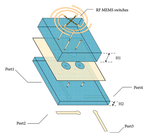
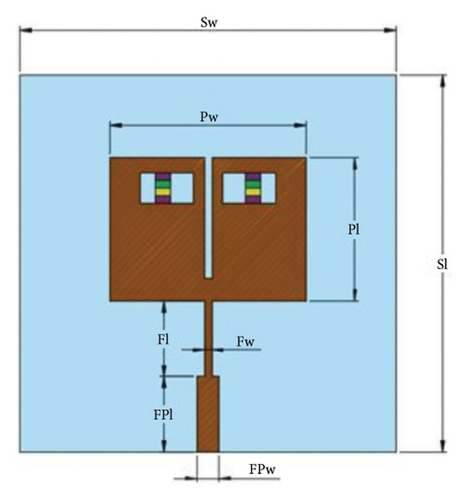
Firstly, MEMS switches can be connected directly to any part of the antenna, including the radiation part, the ground plane, and parasitic elements. Wang et al. in 2023 [92] designed pattern reconfigurable antenna by a placed eight MEMS switches into four width-graded logarithmic spiral antenna units, as shown in Figure 5(a). By selecting different input port and MEMS switching configurations, the length of radiation parts was changed to realize its beam direction. Specifically, the selection of the input port determined the azimuth angle of the beam, and the state of MEMS switches decided its vertical titling angle. However, the introduction of MEMS limited the change of its straight arm length L, resulting in the bandwidth of the axis ratio < 3 dB decreased.
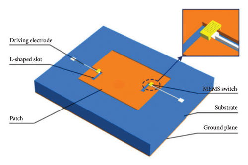
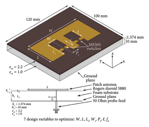
Moreover, MEMS switches can be fabricated in very small sizes and placed in the slots of the antenna. It is worth noting that the position of MEMS switches always needs to be optimized to achieve the desired antenna bandwidth and the radiation pattern. Chen et al. in 2023 [93] proposed an L-slots’ frequency reconfigurable antenna by arranging two MEMS at the corner of an L-slots (width: 0.1 mm), as shown in Figure 5(b). This antenna realized four states of 42.63, 47.65, 53.13, and 56.75 GHz by changing the ON/OFF state of these MEMS switches. The reconfigurable mechanism was to adjust the current distribution around the L-slots by controlling the ON/OFF state of the MEMS switches, so as to change the effective electrical length of antenna. The effect of MEMS switches on the antenna resonant frequency was discussed. However, the antenna pattern in H-plane was slightly distorted. Rajagopalan, Kovitz, and Rahmat-Samii in 2014 [94] detailed the development, design, optimization and implantation of the frequency reconfigurable E-shaped antenna, as shown in Figure 5(c). The MEMS switches were modeled as the ideal switches and their circuit model were chosen according to the simulation accuracy and rapid optimized time. The position of the two MEMS switches was selected as the design variables to optimize the resonant modes. The final optimized results revealed that the impedance bandwidth of the proposed antenna can reach 50%, and the measured results are in good agreement with the simulation results. However, the ideal switch model is difficult to find balance between the accuracy and simulation speed.
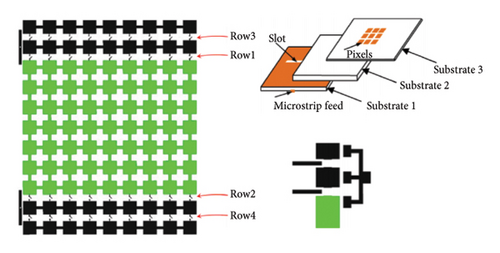
Furthermore, for flexible substrate and deformable antenna geometry, the types and locations of MEMS switches should be codesigned with antenna parts. A nonconventional installation method of MEMS switches was utilized to design the pixelated frequency reconfigurable broadband patch antenna for conformal application by Wright et al. in 2018 [95]. Figure 5(d) depicts the general geometry of this antenna, which included Substrate 1 with a slot and a 50 Ω microstrip feed line, Substrate 2 with 17 mm Roha cell foam core, and Substrate 3 with joined or disconnected pixels. In addition, two MEMS switches were placed on Substrate 1 to control two matching stubs, and 36 MEMS were integrated into Substrate 3 to control the connected state of pixels. By controlling the MEMS switch states, the proposed frequency reconfigurable antenna generated three reconfiguration states, allowing it to operate from 1.13 to 1.7 GHz with a gain of 3–7 dBi, excellent radiation patterns, and low cross-polarization. For the deformable antenna geometry, MEMS switches also need to dynamically coordinate with the antenna structure. However, the antenna performance degradation was observed in measurements due to the EMI caused by bias traces and wiring.
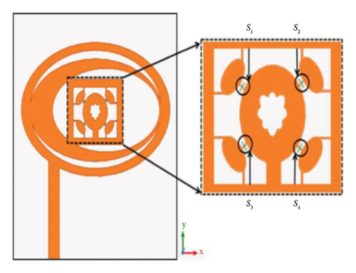
Finally, there are many types of MEMS switches can be used to design the reconfigurable antenna, including series connect connection, series capacitive connection, shunt contact connection, and shunt capacitive. The selection of these methods can refer to both the insert loss, isolation and speed of MEMS switch and the resonant frequencies of the designed antenna. Kumar Naik and Venkata Sai Sailaja in 2024 [96] integrated four shunt capacitive switches into the elliptical-shaped antenna to achieve frequency reconfiguration, as shown in Figure 5(e). By controlling the ON/OFF state, the capacitances of the selected MEMS switches and the length of elliptical patch were changed, resulting in the variation of current distributions. There were four states can achieve different resonant frequency. However, a slight deflection between simulated and measured reflection coefficient was found. Recently, MEMS with the hybrid connection type-like shut-series connection is playing an important role to overcome the problems which are faced by the other connections. Navarajan et al. in 2022 [97] applied two shunt-series MEMS switches into the rectangle antennas to achieve the frequency reconfigurable antenna, as shown in Figure 5(f). The shun-series MEMS switch was modeled as two capacitance, one resistance, and one inductance, and the ON/OFF state can be varied with these parameters. However, the bandwidth and gain decreased in OFF-OFF state.
Table 3 presents a summary of various research works done exclusively for the design of reconfigurable antennas based on MEMS switches. It is inferred that MEMS switches have lots of types with different characteristics, which determines their application scene. MEMS switches can be incorporated with new materials and rigid/flexible substrates, except for controlling the ON/OFF state of the circuit such as PIN diodes and varactors. In addition, the type and placement of MEMS switches play a crucial role in the design of performance reconfigurable antennas. However, the high-intensity field properties and structural complexity of MEMS switches restrict their use in the low–power consumption sector.
| Reference | Type of antenna | Antenna size (length × width × height) ( mm3 ) | Number of MEMS | Type of reconfiguration | Design highlights | Advantages | Limitations |
|---|---|---|---|---|---|---|---|
| [92] | Width-graded logarithmic spiral antenna | None × none × 0.2 | 8 | Frequency reconfigurable antenna | Connected directly to the radiation patch | Good impedance bandwidth, good polarization, and high gain | The bandwidth of the axis ratio <3 dB decreased |
| [93] | L-slot antenna | 10 × 10 × 0.5 | 2 | Frequency reconfigurable antenna | Placed into the slots of the antenna | Compact size, good impedance bandwidth, and high gain | H-plane pattern was slightly distorted |
| [94] | E-shaped patch antenna | 120 × 1000 × 10 | 2 | Frequency reconfigurable antenna | MEMS’ position was optimized by the PSO algorithm | Simple geometry, widen bandwidth, and high gain | The ideal switch model had low accuracy |
| [95] | Pixelated patch antenna | 470 × 178 × 19 | 38 | Frequency reconfigurable antenna | Codesign MEMS with antenna | High gain, excellent radiation pattern, and low polarization | The antenna performance degradation caused by bias traces and wiring |
| [96] | Elliptical-shaped antenna | 30 × 28 × 1.59 | 4 | Frequency reconfigurable antenna | Shunt capacitive switches | Compact size, good impedance, and high gain | A slight deflection between simulated and measured reflection coefficient |
| [97] | A parasitic patch array | 50 × 50 × 1.6 | 2 | Frequency reconfigurable antenna | Shun-series MEMS switches | High efficiency, tunable frequencies, and good radiation patterns | The bandwidth and gain decreased in the OFF-OFF state |
3.4. Reconfigurable Antennas Based on Optical Switches
The optical switches–like photodiodes use light to control the connection or disconnection of the circuit. Different from other nonoptical switches, it can be operated remotely to change the circuit connect state of radiation parts, thus realizing antenna performance reconfiguration [98]. Moreover, they have the advantages of fast response speed and no parasitic radiation, which will not affect the antenna performance [99]. Up to now, these reconfigurable antennas are usually utilized for some special application scenes [100]. Figure 6 shows serval typical reconfigurable antennas with photodiodes. Optical switches, similar to the PIN diodes, also have two typical states (ON and OFF). The optical switches are initially reverse-bias, operating in the OFF state, and they are modeled as an inductor in series with a parallel resistor and capacitor. However, when the infrared light is illuminated to the optical switches, the state can be changed to the ON state, and its equivalent circuit model consists of resistors and inductors in series.
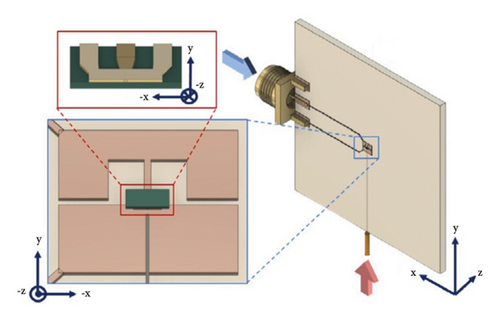
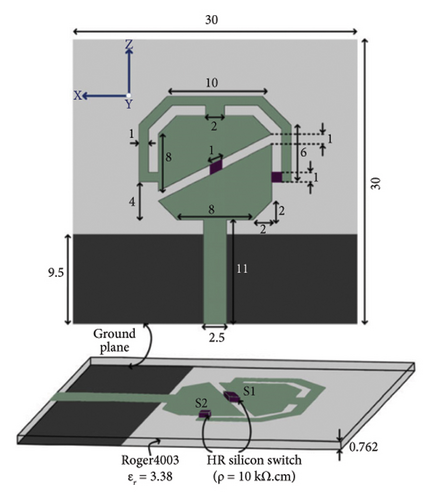
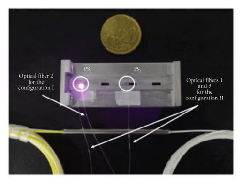

Firstly, optical switches can be directly integrated into the antenna part. Vega et al. in 2024 [101] designed a frequency-agile, photodiode-coupled asymmetrical inductive dipole antenna, as shown in Figure 6(a), which allowed voltage-bias controlled tuning of frequency in the Ka band from 29 to 34 GHz. The photodiode was used to directly connect the asymmetric arms, and its equivalent circuit model was also given. Based on the equivalent circuit model, the conjugate matching of maximum power under different operating frequencies is carried out. However, adjustment of the reverse bias changes the return loss response.
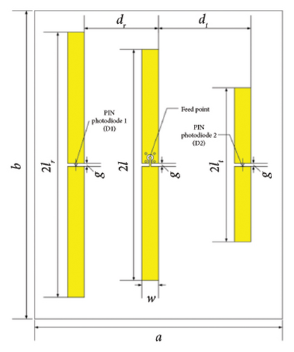
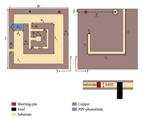
Secondly, optical switches are capable of varying the geometry of the antenna. Zhang et al. in 2018 [102] applied two photodiodes (D1 and D2) as a circuit switch to design a pattern reconfigurable Yagi-Uda antenna by transforming the connection of antenna geometry, as shown in Figure 6(b). When D1 and D2 were both working in the ON state, the director and reflector of the Yagi-Uda antenna were all connected, performing maximum radiation direction toward the shortest strip. However, when D1 and D2 operated in the OFF state, their direction and reflector were transformed into parasitic segments with impedances and arranged in an array with the driven dipole, realizing a change in the direction of the maximum radiation to the longest strip. However, the resonant frequency was shifted and the bandwidth was decreased. Ciflik et al. in 2024 [103] designed a tissue-independent reconfigurable antenna that operated in the ISM band by introducing the photodiodes. As shown in Figure 6(c), the photodiode was placed between the rings of this antenna. The introduction of photodiode can effectively improve the antenna geometry. In the OFF state, this antenna operated in the respective frequency band of the skin and muscle tissue; when the photodiode became the ON state, its operated frequency was suitable for the fat tissue. However, there is a small-level difference between the circuit results and the CST simulations.
In addition, the optical switches can be designed to redistribute the surface current on the antenna by changing their working state. As shown in Figure 6(d), Abdul et al. in 2018 [104] designed a frequency reconfigurable antenna with two Si-based optical switches. This antenna was composed of two regions, an upper rounded triangle and a feeder line connected to the lower rounded triangle. The two Si-based switches (S1 and S2) were used to connect the above triangles. This antenna had several effective patterns when viewed from the feed point. By varying the ON and OFF states of two optical switches, the surface current was redistributed through different paths. Controlling their state can achieve the frequency reconfiguration with frequency bands varying from 1.9, 2.75, 3.7, 4.1, 4.6, 4.8, and 7.6–11 GHz. However, the antenna patterns at certain frequencies were slightly distorted due to the marginal of the surface current.
Finally, the optical switches can be used to change the effective electrical length or the length of the stubs. As shown in Figure 6(e), Da Costa et al. in 2017 [105] used two optical switches (PS1 and PS2) on two different slots of a slotted waveguide antenna array to provide frequency reconfiguration by changing the slot electrical length. The PS1 strategically covered the first slot, while the PS2 partially covered the third slot. The electrical length could be changed by entirely or partially closing the slot, thus reconfiguring bandwidth (28–38 GHz) and radiation pattern (the main radiation direction varies from 28° to 38°). However, all combinations of two optical switches were not discussed. Reji and Manimegalai in 2023 [9] designed a lighted controlled frequency antenna for 5 GHz, WLAN, and radio altimeter application. As shown in Figure 6(f), this antenna consisted of a radiating V-shaped structure and three stub arrangements with two optical switches. The optical switches were used to adjust the length of these stubs. Through the joint operation of optical switches and DC bias circuit, the reconfiguration is realized. Specifically, under the condition of no light applied and DC bias voltage, the antenna can operate 4.1–4.63 GHz. When the light was applied to the photodiodes without DC bias voltage and DC bias voltage was applied without light, the antenna can be reconfigured from 3.43 to 3.6 GHz and from 4.8 to 5.4 GHz, respectively. However, its gain was changed with different configurations.
Table 4 shows various research works to realize the reconfigurable antennas based on optical switches. From Table 4, it is evident that the optical switches have a similar function to other switches, such as PIN diodes and varactors. Different from other switches, the optical switches need light to illuminate them, thus changing their working state (ON or OFF state). Notably, the parameters of their equivalent circuit must be accurately measured for both ON and OFF states, and their applications usually need the appearance or disappearance of the light.
| Reference | Type of antenna | Antenna size (length × width × height) ( mm3 ) | Number of optical switches | Type of reconfiguration | Design highlights | Advantages | Limitations |
|---|---|---|---|---|---|---|---|
| [101] | A dipole antenna | 2.5 × 2.21 × 1.5 | 1 | Frequency reconfigurable antenna | Directly integrated into the antenna part and equivalent circuit model | Compact size, good impedance bandwidth, and high directivity | The return loss was changed by the tuning of reverse bias |
| [102] | A Yagi-Uda antenna | 150 × 200 × 1.63 | 2 | Pattern reconfigurable antenna | Varying the geometry of the antenna | Good patterns, high gain, and good agreement between simulated and measured results | The resonant frequency was shifted and the bandwidth was decreased |
| [103] | A split resonator antenna | 100 × 100 × 6.71 | 1 | Frequency reconfigurable antenna | Varying the geometry of the antenna | Good impedance, uniform radiation pattern, and acceptable gain | The circuit results had a small-level difference with the CST simulation |
| [104] | A two-triangle region antenna | 30 × 30 × 0.762 | 2 | Frequency reconfigurable antenna | Redistribute the surface current | Compact size, good patterns, and high efficiency | The pattern at certain frequencies was slightly distorted |
| [105] | A slotted waveguide antenna array | 4.65 × 44.29 × 1 | 2 | Frequency and pattern reconfigurable antenna | Change the effective electrical length | High gain, good impedance, and high efficiency | All combinations of two photoconductive switches were not discussed |
| [9] | A V-shaped antenna | 44 × 28 × 1.52 | 2 | Frequency reconfigurable antenna | Adjust the length of these stubs | Compact size, simple geometry, and good impedance bandwidth | The gain was changed with the different configuration |
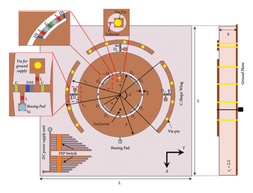
In recent years, compound/hybrid reconfigurable antennas have received more and more attention due to their ability to increase the channel capacity and overcome the drastic effect of time-varying channels [36]. Many studies have been proposed to achieve two or more types of the frequency, pattern, and polarization reconfiguration. In fact, it is difficult to combine the above three reconfigurations. This is because numerous challenges must be addressed [106–108], such as the interaction between these performance reconfigurations, the complexity caused by the integration of electronic switch, and the low precision and reliability of antenna fabrication. For example, Muthuvel et al. in 2021 [109] attempted to design a concentric circle compound reconfigurable (frequency, polarization, and pattern) antenna with the help of varactors and PIN diodes. As shown in Figure 7(a), this antenna geometry consisted of a concentric circle, an arc slot etched from the inner circle, and C-shaped wings located around the circle. Varying capacitance of varactor diodes located between the circular patch and ring from 4.15 pF (0 V) to 0.94 pF (6 V) can tune its operating frequency from 2.10 to 2.90 GHz. Its PIN diode (D1–D8) states in the arc slot placed on the edge of the inner circular were controlled to achieve polarization reconfiguration, including LP/RHCP/LHCP. The connection state of the concentric circle and C-shaped wing was used to design the pattern reconfiguration, which was tilted to 0° and ±50° at all tunable frequencies. However, there was a slight frequency agility caused by fabrication tolerance soldering imperfections, and approximate boundary condition in the computational domain. To overcome these challenges, some strategies were proposed, such as introducing different types of switches, and integrating many modulars with different performance reconfiguration. Kamran Shereen et al. in 2023 [110] designed a novel hybrid reconfigurable and bandwidth-enhanced antenna. This antenna was composed of frequency reconfigurable modular (patches P1_28 and P2_38 connected via two PIN Diodes), pattern reconfigurable modular (four parasitic rectangle conductor), and polarization reconfigurable modular (4 PIN diodes symmetrically placed on each patch to bridge the gap between the center patch and outer triango-truncated edge at the corners), as shown in Figure 7(b). To achieve the desired performance reconfiguration, a total of 18 PIN diodes were configured, 2 of which are used for frequency reconfiguration from 28 to 38 GHz, 8 are used for ±90° pattern reconfiguration, and 8 of which are used for polarization, such as LP, RHCP, and LHCP. However, due to the increase of PIN diodes, the bias circuit becomes very complex.
In summary, the design mechanism of the above electrical switches is related to the control of their ON and OFF states. The PIN diodes stand out for their quickly switchable and high switching speed. Different from PIN diodes, varactor diodes can offer continuous tuning to easily redistribute the surface current. MEMS switches can be morphed with antenna substrate, which provides a potential design for conformal reconfigurable antennas. Optical switches rely on light-sensitive materials to change their working state, thus responding to the light variation of the environment. However, they are limited by their working condition and the antenna structure due to their physical structure. Therefore, researchers should pay more attention to the relationship between the antenna structure and the control of the switch ON/OFF state to achieve performance reconfiguration. Moreover, introducing various switches in a single antenna, designing compound performance, and applying smart algorithms to optimize their number and position will be the future development for the reconfigurable antennas based on electrical switches and optical switches.
4. Reconfigurable Antennas Based on Structure Physical Change
Reconfigurable antennas designs based on the physical structure change do not require bias circuits or optical environments such as electrical switches. The reconfigurable antennas based on the structure physical change can potentially provide high power handling capability, lower loss, and offer continuous tuning [111]. Moreover, they usually rely on the physical movement of the antenna structure or other parts, mainly including the fold [112], rotation [113], and flow [114]. Thus, origami reconfigurable antennas, microfluidic reconfigurable antennas, and mechanically movement reconfigurable antennas are discussed in this section, respectively.
4.1. Reconfigurable Antennas Based on Origami Structure
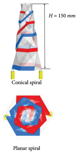
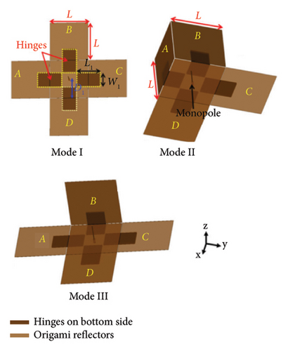
As an ancient oriental art and emerging frontier science, origami design covers the intersecting fields of mechanics, materials, mathematics, control, and other disciplines [115]. Compared to conventional antennas, origami antennas only need to fold paper sheets as the substrate and copper film as a radiation conductor [116]. In recent years, origami technology has been extensively exploited in the creation of deployable and reconfigurable engineering systems due to its intriguing properties of self-foldability, multistability, and programmable curvature and collapse [117, 118]. Figure 8 shows several typical reconfigurable antennas.
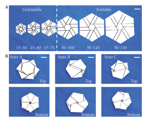
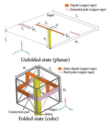
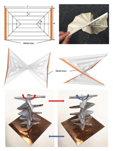
Primarily, folding and unfolding 3D origami geometry can change the effective height or length of antennas. Zhang et al. in 2020 [119] proposed a typical hexagon-twist origami frequency reconfigurable antenna realized by thermal triggering, as shown in Figure 8(a). Its design rules included the center symmetry of radiation parts, the large degree of short circuits, and the foldability of the hexagon-twist structure media board. The radiation patch was arranged along the distribution and arrangement of the substrate folds. Under the influence of temperature, the folded stable configuration can self-deploy due to the property of the material, and its geometry can also be controlled by the self-deployment temperature. Using such unique features and design principles, the antenna had nine operating modes from the S-band to the C-band. However, the H-plane pattern was omnidirectional, but E-plane pattern was non–omnidirectional due to the electric field in the vertical plane titled down. Lee et al. [120] designed a frequency reconfigurable antenna by changing its effective length. Figure 8(b) depicted this antenna geometry with unfolded state and folded state, which consisted of the main dipole and two isolated patch poles. The dipole length was extended with its geometry changing from flat paper (in the unfolded state) to the cube (in the folded state), achieving the frequency reconfiguration from 1.23 to 0.77 GHz. However, the pattern had discrepancy between simulation and measurement due to the slight antenna geometry.
In addition, the transformation from a 2D planar origami pattern to a 3D structural geometry can determine the direction of the antenna on the radiation plane, thus generating new different radiation patterns. Liu et al. in 2017 [121] proposed a conical spiral pattern reconfigurable antenna with two arms, as shown in Figure 8(c). This antenna was very compact and easily transformed from a 2D planar to a 3D mode without any additional support or hinges, which benefits from the buckling of a thin conical shell under torsional loads.
The main beam was reconfigured from two to one when the antenna changed from the unfolded state to the folded state. However, the gain was decreased when it changed from conical spiral to planar spiral. Different from the conical spiral pattern reconfigurable antenna, Sha and Lim in 2019 [122] proposed a pattern and bandwidth reconfigurable antenna based on the smart shape memory polymer hinges. This antenna consisted of a signal monopole antenna with origami reflectors, as shown in Figure 8(d). When the shape memory polymer hinges actuated the reflectors, the antenna generated three modes including Mode I (all reflectors were unfolded), Mode II (two reflectors were folded perpendicular to the ground plane), and Mode III (only one reflector was folded perpendicular to the ground plane). From the perspective of pattern reconfiguration, Mode I, Mode II, and Mode III exhibited omnidirectional radiation, respectively. When the origami reflector pairs were activated, it showed four switchable beam directions, and when each origami reflector was individually activated, it showed four switchable directional radiation. However, the simulated and measured reflection coefficient had slight disagreement because the simulated results was based on an ideal centrosymmetric model and cannot be exactly achieved by the prototype.
Finally, the origami geometry can change the direction of the electric or magnetic current source of the antenna to achieve polarization reconfiguration. Figure 8(e) illustrates a segmented helical origami antenna with polarization reconfiguration designed by Yao and Georgakopoulos in 2018 [123]. This antenna consisted of a series of identical rectangle hyperbolic paraboloid origami units with the segmented trace, which realized two stable states: left-handed and right-handed state. The above origami unit can quickly switch between the two stable states by fixing the bottom edge and rotating its top edge, thus switching between LHCP and RHCP. However, the patterns for Mode III-1, 4 were not measured.
Table 5 compares the features of the reconfigurable antenna based on an origami structure. As can be seen from Table 5, the origami reconfigurable antenna has high design flexibility. Moreover, this design method has the advantages of good foldability, thermal stability, and lightweight. However, the roughness of the paper structure and mechanical deformation of metal patches always lead to deterioration in electromagnetic radiation performance. The reconfigurable mechanism is based on the conversion between 2D structure and 3D structure, which can change the space distribution, length, and height of the antenna patch. Thus, how to ensure the antenna performance before and after folding the antenna is a challenge. This is because the materials of origami antenna often show different physical properties during folding or unfolding, such as modulus of elasticity, and coefficient of thermal expansion, and it is difficult to maintain the properties of the stable states, such as height and vertical position. To solve this challenge, many researches have been proposed including 3D printed technology and smart materials. For example, Wang et al. in 2020 [124] demonstrated a tri-stable origami structure achieved through multimaterial 3D printing, utilizing the classic square-twist origami configuration. By modulating the material properties and geometric parameters of the heterogeneous polymer structure, the folding potential energy of origami paper is changed, and the design principle of multistable structure in square-twist origami paper configuration is established. Under the thermal stimulation, the stiffness of the deformable structural paper region rapidly and significantly decreases, leading to an increased bending freedom in the paper region of the structure. This allows for self-deployment by releasing the prestored energy in the elastic crease areas. Based on this unique characteristic and design principle, they designed and fabricated a frequency-reconfigurable origami antenna prototype with five distinct operational modes, which maintains consistency before and after folding.
| Reference | Type of antenna | Antenna size (mm) | Number of modes | Type of reconfiguration | Design highlights | Advantages | Limitations |
|---|---|---|---|---|---|---|---|
| [119] | A hexagon-twist origami antenna | 30-100-30 | 9 | Frequency reconfigurable antenna | Changing its effective height | Good impedance and high gain | The E-plane pattern was non–omnidirectional |
| [120] | An origami flasher dipole antenna | 182 × 182 × 0.009 | 2 | Frequency reconfigurable antenna | Changing its effective length | Easy transformation, good impedance, and high gain | The pattern had discrepancy between simulation and measurement |
| [121] | A conical spiral antenna with two arms | H = 150 | 2 | Pattern reconfigurable antenna | Change the direction of the antenna | High gain | The simulated and measured reflection coefficient had slight disagreement |
| [122] | A signal monopole antenna | 28 × 1.6 | 3 | Pattern reconfigurable antenna | Dynamically change structural geometry | Low cross-polarization, and good impedance | The gain was decreased |
| [123] | A parasitic patch array | 100 × 84 | 2 | Polarization reconfigurable antenna | Change the orientation of the electric or magnetic current source | High efficiency, good circular polarization, and high gain | The patterns for Mode III-1 and 4 was not measured |
4.2. Reconfigurable Antennas Based on Microfluidic Structure
In recent years, microfluidics technology has been used for designing reconfigurable antenna [125]. Microfluidics are often used to work as the radiator or parasitic element of antennas [126] or fill the channel [127] to reshape the antennas to achieve antenna performance reconfiguration. Moreover, as a typical microfluidics, the liquid metal EGaIn alloy [128] has many novel material properties of nontoxicity, good fluidity, and high conductivity, which provides a promising prospect for designing a reconfigurable antenna. Many studies on EGaIn reconfigurable antennas have been published, as shown in Figure 9.
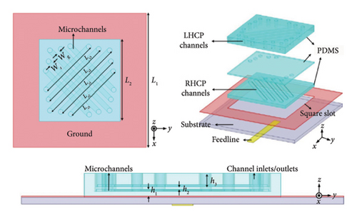
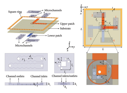
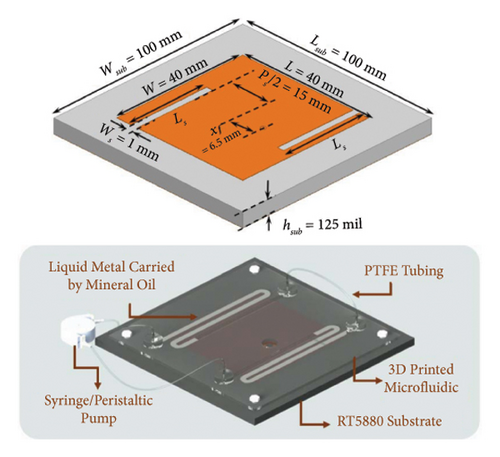
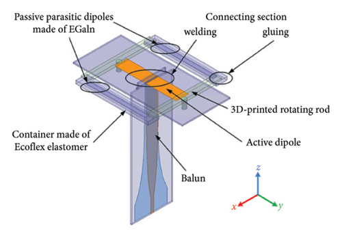
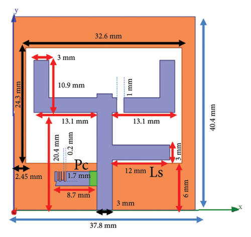

Firstly, controlling the direction and length of microfluidics in the channel is a common design method. Liu et al. in 2020 [129] proposed a frequency and polarization reconfigurable slot antenna with liquid metal. Figure 9(a) depicts the geometry of this antenna, which was composed of a polydimethylsiloxane structure with narrow microchannels and a square slot antenna. The polarization reconfiguration was achieved by injecting the liquid metal or keep them empty in +45° and −45° channels of the x-axis, referring to the LHCP, RHCP, and LP. Moreover, by controlling different lengths of microfluidics in microchannels in different polarization states, frequency reconfiguration was achieved. However, the reflection coefficients of LHCP and RHCP were different due to the liquid metal strips were at different height in the two states. Wang et al. in 2023 [130] proposed a frequency and polarization wideband cross-dipole antenna. As shown in Figure 9(b), this antenna consisted of a pair of rectangular dipoles, curved phase-shifted rings, and a square ring. The liquid metal was attached to the dipole arm as parasitic branch. The LHCP and RHCP were switched by loading EGaIn at different positions of the antenna, and frequency reconfiguration was achieved by adjusting the length of liquid metal at corresponding positions. However, its measured maximum gain for the ±30° configuration was decreased over time due to the consumption of NaOH.
Secondly, the continuous movement of the liquid metal can achieve the frequency reconfiguration. A wideband frequency reconfigurable antenna with liquid metal and 3D-printed microfluidics was designed by Song et al. in 2019 [131]. As shown in Figure 9(c), the geometries consisted of three pairs of composite grooves and a microfluidic channel connected to the top of the metal layer. By continuously tuning and switching the liquid metal-loaded slot in the channel, the frequency reconfiguration was achieved without significant change in its radiation pattern. However, the S-parameters were different from the broadband narrow transmission line due to the small size of its feeding pin.
Moreover, the relative position of antenna parts can be changed by the microfluidics. As shown in Figure 9(d), Hao et al. in 2021 [132] proposed a pattern reconfigurable Yagi-Uda antenna based on liquid metal. This antenna included a dipole fed by a balun and two coupled parasitic dipoles made of liquid metal embedded in microfluidic channels. The above dipole lengths were stretched by spinning its rods at different angles, which made the antenna exhibit pattern reconfiguration from bidirectional radiation (when the parasitic dipoles have equal lengths) to directional radiation toward the shorter dipole (when the parasitic dipoles have different lengths). However, when the channel was prolonged, its width was naturally changed to ensure the desired volume of liquid metal.
Finally, the microfluidics can be used as the feed parts to excite different polarization mode. Liu et al. in 2022 [133] designed a wideband slot antenna with polarization reconfigurability by using liquid metal. This antenna consisted of a small rectangular ring, a microstrip of symmetric coplanar waveguide, and three horizontal channels, as shown in Figure 9(e). By loading the liquid metal into the left or right channels, the RHCP and LHCP were achieved, respectively. Moreover, when there is no liquid metal in the channels or fulfill liquid metal, the LP can be achieved. However, the simulated and measured impedance bandwidth had discrepancies due to fabrication tolerance and permittivity error of the substrate. Sharbati et al. in 2023 [134] presented a novel slot reconfigurable antenna with circular polarization by using liquid metal switching capacity. Figure 9(f) depicted the geometry of this antenna, which was composed of four arms on the feed line and a square slot on the ground plan. The liquid metal switch was used to connect the rectangular parasitic element with feed line. Controlling the liquid metal in the microfluidics by applying a voltage to move and remove the liquid metal can make this antenna generate circularization polarization. However, the patterns were distorted at higher frequencies.
Table 6 shows the performance comparison of the reconfigurable antenna based on the microfluidic structure. As can be seen from Table 6, reconfigurable antennas based on microfluidic structures are usually designed by controlling the microfluidic state in the channel. These antennas are more efficient in terms of power processing and are high linear because they do not rely on electronic switches, making them ideal for high-power applications. However, the movement of liquid metal in channels often requires external physical force from micropumps [135], syringes [136], or electrochemical methods [137], which will influence the reliability of the antenna system.
| Reference | Type of antenna | Antenna size (length × width × height) ( mm3 ) | Number of microchannels | Type of reconfiguration | Design highlights | Advantages | Limitations |
|---|---|---|---|---|---|---|---|
| [129] | A square-slot antenna | 49.2 × 49.5 × 6.524 | 10 | Frequency and polarization reconfigurable antenna | Controlling lengths of microfluidic | High gain and low cross-polarization | The reflection coefficients of LHCP and RHCP were different |
| [130] | A cross-dipole antenna | 75 × 75 × 1.5 | 6 | Frequency and polarization reconfigurable antenna | Controlling lengths of microfluidics | Good impedance matching, small size, and wide frequency band | The measured maximum gain for the ±30° configuration was decreased |
| [131] | A patch antenna with switchable slots | 100 × 100 × 3.175 | 2 | Polarization reconfigurable antenna | Continuously tuning and switching the liquid metal–loaded slot | Low cross-polarization and high gain | The S-parameters were different from the broadband narrow transmission line |
| [132] | A Yagi-Uda antenna | 84 × 10 × 0.813 | 4 | Pattern reconfigurable antenna | Change the relative position of antenna parts | High gain, good impedance, and low cross-polarization | When the channel was prolonged, its width was naturally changed |
| [133] | A wideband slot antenna | 40.4 × 37.8 × 1.6 | 1 | Polarization reconfigurable antenna | Used as the feed parts to excite different polarization modes | Simple configuration, compact size, and good impedance | The simulated and measured impedance bandwidth had discrepancies |
| [134] | A slot antenna | 31 × 29 × 1.5 | 2 | Polarization reconfigurable antenna | Used as the feed parts to excite different polarization modes | Compact size, wide impedance bandwidth, and high efficiency | The patterns were distorted at higher frequencies |
4.3. Reconfigurable Antennas Based on Mechanical Movement
Reconfigurable antennas based on mechanical movement with the advantages of agility and inexpensive cost have been developed by utilizing actuators or manual devices [138, 139]. The reconfiguration is achieved by rotating [22] or moving [140] the relative position of the antenna parts, such as the substrate, ground, and feed port radiation patch. Figure 10 shows serval typical reconfigurable antennas based on mechanical movement.
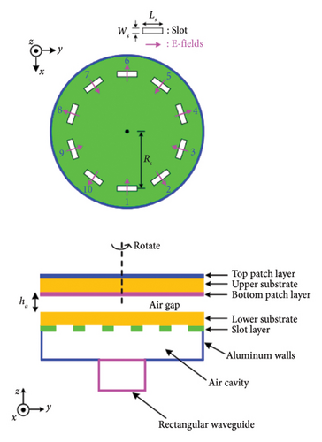
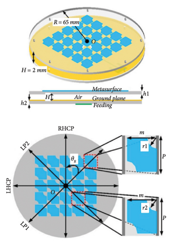
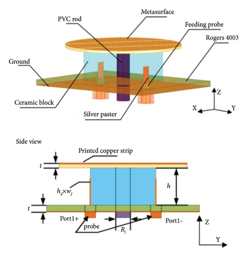
Firstly, rotating antenna parts is one of the commonly used methods to excite different antenna modes. Chen et al. in 2022 [141] designed an mm-wave multi-LP reconfigurable antenna, as shown in Figure 10(a). It included a base with an air-filled cavity, a circular array of slots on the top surface, and an upper substrate printed with an engineered patch layer. Among them, the circular array of slots on the top surface could provide a rotationally symmetrical excitation, and the mechanical rotation of the upper substrate was designed to facilitate the multi-LP reconfiguration. With the combination of the above elements, this antenna switched among five LP states at the mm-wave band. Despite the sidelobe was reduced by modifying the underlay, the measured results were still relatively high (around −10 dB), which may affect the antenna performance in some application. Li et al. in 2023 [142] designed a wideband multipolarization reconfigurable antenna based on the metasurface. As shown in Figure 10(b), this antenna contained an upper layer of metasurface and a bottom layer of circular slot antenna. While keeping the feeding layer stationary and rotating the metasurface layer by 0°, 45°, 90°, and 135°, the desired multipolarization diversity (LP, LHCP, and RHCP) of the proposed antenna was achieved. However, there were some undesired resonate points in the measurement. Shi et al. in 2024 [143] designed a frequency reconfigurable antenna with a top-loaded rotatable anisotropic metasurface. Figure 10(c) shows the configuration of this antenna, which consists of three parts including the dielectric resonator in the middle, the metasurface on the top, the bottom substrate, and a pair of silver paster used as the feeding structure. When the metasurface was rotated, the boundary conditions between the metasurface and the dielectric resonator were modified to achieve different resonant frequency. Specifically, this antenna exhibited a tuning center frequency from 6.46 to 6.94 GHz. However, its radiation efficiency was affected by the metasurface.
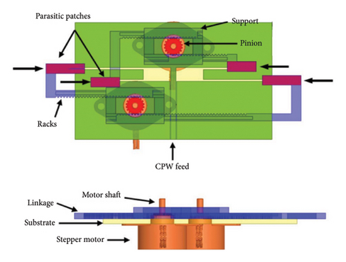
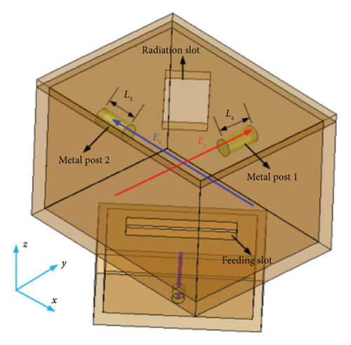
Moving some antenna parts can adjust the effective length or tuning mode. Nassar et al. in 2015 [144] proposed a dual-band frequency reconfigurable slot dipole antennas by mechanically changing the slot lengths. As depicted in Figure 10(d), the proposed antenna geometry included antenna parts, racks, and pinions. The frequency reconfiguration was achieved by using a rack and pinion mechanism to slide its parasitic patches along the antenna to change two slot pairs of different lengths. However, there was a considerable deviation at the upper band, which was attributed to high sensitivity to alignment of the parasitic patches and the symmetry of the slot length compression during the rack movement. Chen et al. in 2021 [145] used two metal posts to design a frequency reconfigurable full metal cavity-backed slot antenna. Figure 10(e) gave the geometry of this antenna, which was composed of a resonant cavity with a radiation slot and a feeding slot, a coaxial-to-waveguide transition and two loaded metal posts. The introduction of the metal posts can achieve a continuous frequency tuning property. The cavity mode can be affected by the metal posts, thus by moving the posts, the single-band, dual-band, dual-mode wideband, and tunable bandwidth with a constant frequency will be achieved. However, how to control the posts was not discussed, which can affect the reconfigurable speed.
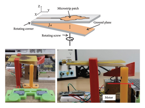
In addition to rotating or moving the antenna parts, titling the antennas arethe very effective methods to design reconfigurable antennas. As shown in Figure 10(c), Duarte et al. in 2020 [146] proposed a frequency and pattern reconfigurable antenna with tetra-circle fractal patch elements. A thin rod of dielectric material was used to change the tilt angle between the back of the substrate and the ground by sliding up and down in this reference. Changing the tile angle can make the antenna work at different frequencies, thus achieving frequency reconfiguration. Moreover, the insertion of the dielectric region filled with air in the tile angle could change the previous effective permittivity and gain pattern, thus realizing the pattern reconfiguration. However, its radiation efficiency was lower at the smallest tilt angle, which affected the antenna performance in some configurations.
Table 7 shows the performance comparison of reconfigurable antennas based on mechanical movement. The design mechanism of the reconfigurable antennas based on mechanical movement is to control the relative location of antenna elements by motor or manual devices. Thus, how to realize the compact structure and fast response is a key design point for these reconfigurable antennas. The above researches mainly focused on the realization of antenna reconfiguration performance through specific rotation angles, displacement distances, and tilt angles, and seldom discussed on the implementation of accurate control inputs. To tackle this challenge, it is crucial to design simple and compact drive devices to improve their reliability and response speed. The balance between mechanical complexity, speed, and reliability can be achieved through the selection of suitable materials, the use of more precise sensors, and the application of advanced control algorithms. For example, Yang et al. in 2017 [22] designed a wideband reconfigurable reflect array antenna using mechanically rotational elements. For realizing the desired rotation, 756 micromotor-controlled elements were fabricated and a complete control circuit board was designed. Specifically, the micromotor adopted was a two-phase four-wire stepper motor with a size suitable for the required pitch. The control circuit board consisted of the computer to microcontroller unit (STM32F103ZCT) to calculate the required phase states and 30 field-programable gate arrays (FPGAs) to control these motor drivers. The desired rotation of the micromotors were directly calculated or predefined using the computer to dispatch to the FPGAs through the MCU, thus achieving beam shaping or manual control functionality. In fact, there was still a challenge of the larger aperture antenna due to the assembly accuracy of micromotors.
| Reference | Type of antenna | Antenna size (length × width × height) ( mm3 ) | Type of reconfiguration | Design highlights | Advantages | Limitations |
|---|---|---|---|---|---|---|
| [141] | An antenna with a circular array of slots | R (14.5) × 3 | Polarization reconfigurable antenna | Change the excitation properties | High gain and low cross-polarization | The measured sidelobe was high (around −10 dB). |
| [142] | A metasurface antenna | R (65) × 2 | Ploidization reconfigurable antenna | Change the excitation properties | Low profile, simple switching strategy, and high gain | Some undesired resonate points appeared in the measurement |
| [143] | A dielectric resonator antenna | R (8.8) × 3.612 | Frequency reconfigurable antenna | Change the boundary conditions | Small size, high efficiency, and low cross-polarization | Its radiation efficiency was affected by the metasurface |
| [144] | A dual-band slot dipole antenna | 100 × 60 × 1.57 | Frequency reconfigurable antenna | Mechanically changing the slot lengths | Good frequency tunability, consistent gain, and radiation patterns | A considerable deviation at the upper band appeared |
| [145] | A full-metal cavity-backed slot antennas | 64 × 60 × 79 | Frequency reconfigurable antenna | Excite different antenna modes | Independent tunability, good impedance bandwidth, and high efficiency | The controlling strategy of the posts was not discussed |
| [146] | A ground plane tilted microstrip antennas | 50 × 50 × 1.57 | Frequency and pattern reconfigurable antenna | Change the relative position of antenna parts | Simple geometry, high gain, and good directivity | The radiation efficiency was lower at the smallest tilt angles |
In summary, the design mechanism of the physical structure change is related to how to handle the relative position relationship between each antenna element. Origami reconfigurable antennas have the highest design flexibility and their reconfigurable mechanism mainly lies in the origami transformation between 2D structure and 3D structure. Different from origami structures, reconfigurable antennas based on the microfluidic structure need to consider the relationship between microfluidic properties and microchannel, especially controlling the fluid of microfluidics in the channel. For reconfigurable antennas based on mechanical movement, rotating, moving or titling one or more parts of the antenna is a common design method, which is also the difference between this method and the origami structure method with the whole geometry change of the origami structure. However, the performance reconfigurations rely on additional continuous power supplied such as pump or motor and so on, which means its reliability will be reduced. Therefore, how to ensure reliability and minimize energy loss is equally important for designing good performance reconfiguration. Introducing new manufacturing technologies to achieve more flexible and diverse design solutions, improving the reliability of mechanical motion, and applying intelligent control strategies to develop reconfigurable antennas with adaptive capabilities will be the future research development.
5. Reconfigurable Antennas Based on Smart Materials
Reconfigurable antennas based on smart materials represent a novel antenna technology that leverages advanced material science to alter antenna performance. The utilization of smart materials enables the adjustment and reconstruction of antenna properties such as shape, size, and dielectric constant according to specific requirements, thereby facilitating flexible antenna designs [147–149]. In addition, smart materials possess the capability to respond to external stimuli such as electric fields, magnetic fields, and light, allowing for the modulation of antenna electromagnetic characteristics including frequency, radiation pattern, and polarization. Many smart materials can be used to design reconfigurable antennas, as shown in Figure 11, including phase-change material [150], liquid dielectric [151], metallic micromesh [152], graphene [46], liquid crystals [153], and SMA [154].
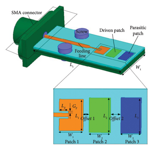
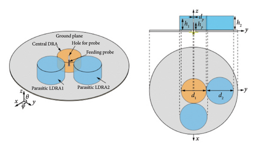
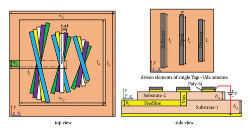
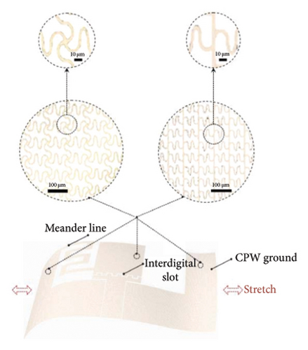
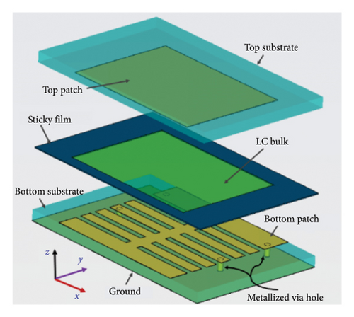
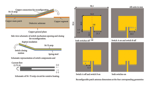
5.1. Reconfigurable Antennas Based on Phase-Change Materials
Phase-change materials are often used as switches, and their electrical properties can vary with the different external stimuli [160]. The advantages of phase-change materials are that specific states can be generated by using electrical or optical excitation [161]. Wong et al. in 2019 [155] used the phase change material to design a novel pattern reconfigurable antenna with switched beams. Figure 11(a) depicted its geometry, which consisted of a driven path (patch 1) and two parasitic patches (Patch 2 and Patch 3) with the phase-change material. The above two parasitic patches were treated as elements with switchable capability between amorphous and crystalline states, and they coworked with the driven patch radiator. When the laser was applied to Patch 2, the material operated in a crystalline state with high conductivity, during which its electric field was coupled to form a Yagi-Uda-type antenna. Therefore, the radiation pattern can be tiled and reconstructed by controlling the activation state of two parasitic patches. However, the resonant frequency was shifted to the right and the bandwidth was decreased during the pattern reconfiguration.
5.2. Reconfigurable Antennas Based on Liquid Dielectric Materials
Liquid dielectric materials are popular for the special nature of the liquid. Different from microfluidics, there are lots of liquid dielectric materials that can be used to design reconfigurable antennas including pure water [162], seawater [163], and even any liquid [32]. In addition to using the liquid dielectric as the antenna, the liquid dielectric materials can also be loaded into the metal-based antenna structure to form a liquid auxiliary antenna. There are many ways to achieve a reconfigurable antenna, such as changing the dielectric, the height, length of the designed antennas. As shown in Figure 11(b), Ren et al. in 2020 [26] proposed a pattern reconfigurable and polarization antenna with a central dielectric resonator antenna and two parasitic dielectric resonator antennas. Its pattern can be changed by controlling the flow of liquid in the parasitic dielectric resonator. When only the central dielectric antenna was radiated, an omnidirectional pattern was realized, while a unidirectional pattern was generated after the parasitic dielectric antennas joined. Therefore, omnidirectional radiation and unidirectional radiation with x-polarization or y-polarization were achieved by using this principle. Obviously, the design of this type of reconfigurable antenna needs to consider various aspects such as material properties, antenna structure, and performance regulation for the achievement of efficient, stable and controllable adjustment of antenna performance. However, the E-plane had an evident tilt angle due to the antenna was asymmetric.
5.3. Reconfigurable Antennas Based on Graphene Materials
Graphene material is a typical two-dimensional material with unique mechanical, electrical, and optical properties that can behave like metal at high chemical potential [164]. They are usually used in specific operating frequencies for the terahertz band and are easy to achieve performance reconfiguration when working in conjunction with the patch antennas [165]. Gotra et al. in 2020 [156] designed a beam reconfigurable graphene-based Yagi-Uda antenna with five iterations of driven elements (these iterations were aligned with each other at different angles), as shown in Figure 11(c). Each iteration could be individually biased by using external bias circuit to control its chemical potential. Therefore, its main lobe efficiently varied from −65° to 65° by maintaining the chemical potential of driven elements. However, the control range and stability of graphene materials need to be improved, and their loss issues in the THz frequency range also need to be addressed [166]. However, any change in the height leaded to the change in operating frequency.
5.4. Reconfigurable Antennas Based on Stretchable Micromesh Structures
The stretchable micromesh structures can make antennas smaller and lighter than conventional antennas, and the size reduction of stretchable micromesh antennas is achieved by using the resonant material property [167]. Moreover, it is an alternative to using liquid metal because the liquid metal may not work due to the leakage of liquid metal caused by the slight torn or small holes of the sealing layer [157]. Jang et al. in 2017 [157] designed a frequency reconfigurable zeroth-order resonant antenna with the stretchable micromesh structure shown in Figure 11(d). This antenna worked under mechanical deformation including folding, twisting, or stretching and was stretched up to 40% without any breakage. With the increase of tensile strain, the resonant frequency was linearly reconfigurable from 2.94 to 2.46 GHz. However, the design of micromesh was often intricate, requiring simultaneous consideration of material properties, structural design, performance control, and various other factors. In addition, given that the structure and parameters of the micromesh directly influence the electromagnetic properties of antennas, it posed a design challenge to simplify the structure while maintaining performance and enhancing integration [168]. However, the gain of this antenna decreased slightly as the tensile strain increases, which meant that the radiation efficiency may be affected in the reconfigured state.
5.5. Reconfigurable Antennas Based on Liquid Crystals
The liquid crystals, due to their outstanding tunability, low operational voltage, and compact volume, are suitable for designing reconfigurable antennas, especially the nematic liquid crystals [147]. Nematic liquid crystals have high dielectric anisotropy, and their dielectric property can be controlled by the applied electric field bias. They exhibit changes in its dielectric constant, refractive index, and other properties in response to external electric fields or temperature variations. Integrating these properties into the antenna design to achieve performance reconfiguration poses a crucial challenge that needs to be addressed. As shown in Figure 11(e), Che et al. in 2018 [158] proposed a liquid crystal-load dual-band metamaterial reconfigurable antenna. This antenna was a kind of sandwich structure, consisting of the top layer, bottom layer with metalized patches, and the liquid crystals injected between them. By changing the bias voltage of the loaded liquid crystals, dynamical and continuous tuning from negative to positive value can be achieved, resulting in beam steering from backward −16° to forward +13° at 7.2 GHz and from backward −9° to forward +17° at 9.4 GHz. However, reconfigurable antennas based on liquid crystals require flexible adjustment of its performance under different operating conditions. To achieve this, it was necessary to design appropriate control mechanisms, such as electric field modulation or temperature modulation that can dynamically alter the properties of the liquid crystal material, thereby enabling the reconfigurable performance of the antenna [169]. However, the measured results showed that its response time was long.
5.6. Reconfigurable Antennas Based on SMAs
For SMAs, a trained shape can be developed and recovered with heat due to the shape memory effect [28]. Nickel–titanium (Ni–Ti), as a commonly used SMA, deforms at low temperatures, deflects when heated, and deforms back to its original shape after being cooled because its potential energy is stored and released during its temperature change [170]. The SMAs are usually used as parts of the antenna directly, and the thermomechanical transformation is for realizing the spatial distribution change of this part, thus realizing the performance reconfiguration of the designed antenna [171]. During the shape transformation process of SMAs, their mechanical properties, such as elastic modulus and thermal expansion coefficient, electromagnetic properties, and permittivity and conductivity, may undergo significant changes. Matching these variations with the electromagnetic design of an antenna to optimize its performance poses a crucial challenge. As shown in Figure 11(f), a frequency reconfigurable antenna with Ni–Ti SMA was developed by Wolcott et al. in 2012 [159]. These switches were connected with a planner patch antenna to create serval electrical signal pathways. Using the separate electric circuit heated the resistive to make the phase of Ni–Ti SMAs vary from martensite to austenite. Therefore, the antenna geometry will begin to change, achieving the frequency reconfiguration from 2.25 to 2.43 GHz. However, the pattern showed a slight deviation due to imperfect contact. Moreover, integrating SMAs with antenna structures while maintaining their shape memory functionality and antenna performance requires addressing integration and packaging issues [47]. To enable the reconfigurable antenna performance, it is necessary to devise appropriate control strategies and algorithms that can precisely manipulate the shape transformation of the SMAs. This may encompass temperature control, stress manipulation, feedback mechanisms, and other aspects [172].
Table 8 summarizes the research works on reconfigurable antennas based on smart materials. The properties of smart materials must be fully considered to realize the cooperative design of the antenna geometry and performance reconfiguration. The dielectric constants change and filling amounts are the important design parameters for the phase-change material, liquid dielectric, and liquid crystals, and the antenna geometry is often the evolution of the conventional antenna. For graphene, stretchable micromesh and SMAs can be integrated directly into conventional antennas or used as alternative parts of conventional antennas. However, it is difficult to control the propriety of these smart materials to satisfy the requirements of performance reconfiguration. Future research will focus on how to more precisely control and optimize the properties of smart materials, which may involve the development of new smart materials and the synergistic optimization of material properties and antenna design. In addition, antenna design will no longer be limited to traditional geometries, and can be flexibly adapted to the properties of smart materials to achieve optimal performance. Finally, through the integration of sensors and smart control systems, antennas will be able to sense changes in the environment in real time and automatically adjust their shape and performance to suit different communication needs.
| Reference | Type of antenna | Antenna size (length × width × height) ( mm3 ) | Type of smart materials | Type of reconfiguration | Design highlights | Advantages | Limitations |
|---|---|---|---|---|---|---|---|
| [155] | Driven patch with parasitic patches | 18.9 × 10 × 0.508 | Phase-change material | Pattern reconfigurable antenna | Controlling the activation state | High gain and low cross-polarization | The resonant frequency was shifted to the right |
| [26] | A dielectric resonator antenna and two parasitic | R (200) × 23 | Liquid dielectric material | Pattern and polarization reconfigurable antenna | Controlling the flow of liquid in the parasitic dielectric resonator | Effective impedance matching, reasonable gain, and high efficiency | The E-plane had an evident tilt angle |
| [156] | A Yagi-Uda antenna | 96 × 96 × 2.6 | Graphene | Pattern reconfigurable antenna | Control the chemical potential | Individually biased iteration, high efficiency, and wide impedance passband | Changing height led the change of operating frequency |
| [157] | A zeroth-order resonant antenna | 8.32 × 11.6 × 0.4 | Stretchable micromesh structure | Frequency reconfigurable antenna | Stretch the micromesh structure | Compact size and low cross-polarization | The gain decreased slightly with increasing tensile strain |
| [158] | A dual-band antenna | 4.3 × 10.8 × 0.065 | Liquid crystals | Pattern reconfigurable antenna | Control the dielectric property | Compact size, dynamically continuous tunability, and good impedance | The measured results showed that its response time was long |
| [159] | A planner patch antenna | 96.1 × 82.9 × 1.575 | SMA | Frequency reconfigurable antenna | Working as a part of the antenna | High gain, good impedance, and compact size | The pattern showed a slight deviation |
6. Reconfigurable Antennas Based on Bistable Composite
The bistable composite is a deformable lightweight structure with two stable configurations, which can be maintain without any continuous energy supply and has the characteristics of adapting to large deformation [173, 174]. Bistable composites are usually composed of two or more different materials. The bistable behavior is determined by the arrangement of fibers, the type of matrix, and the interfacial bonding strength. As shown in Figure 12(a) [175], when the structure deforms, the bistable structure exhibits multiple local minimum points due to the existence of prestress. Once the potential energy barrier is breached, the bistable structure can achieve a stable state switch. Specifically, under the existence of external loads, bistable structures can be freely switched to different stable configurations by snapping through, and each configuration has a certain bearing capacity. After switching, the bi-stable structure can keep in the stable configuration corresponding to the minimum potential energy. For example, the thermal bistable antisymmetric composite laminates composed of unidirectional fiber and epoxy resin can usually form two stable configurations due to the difference of elastic modulus and thermal expansion in axial and transverse fiber directions. These configurations are cylindrical, and when the layers are stacked vertically, the axes of curvature are orthogonal to each other, making performance reconfiguration of antenna possible. The bistable composite is usually used as the substrate [176], and the metal patch can be integrated on [177] or into the bistable substrate [48], thus obtaining a multifunctional composite structure with antenna performance reconfiguration and morphing structure. In addition, its large deformation is useful for achieving the antenna performance reconfiguration and meeting the requirements of large amplitude and large angle. However, studies on bistable composite reconfigurable antennas are very limited. The cylindrical shell structure is a common type used as the substrate, and the performance reconfiguration of antennas is achieved by snapping through, as shown in Figure 12.

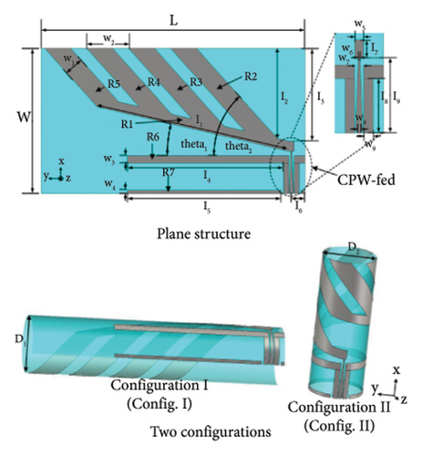
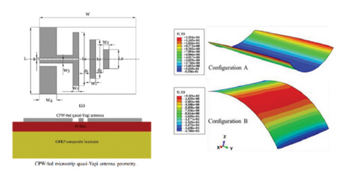
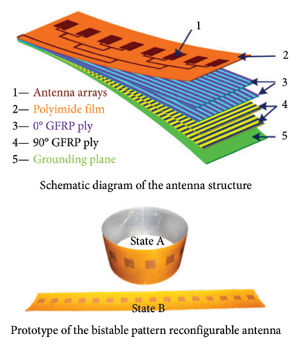
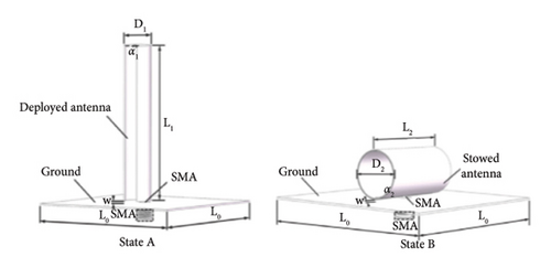
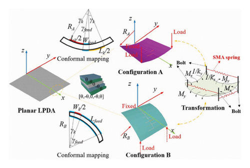
Primarily, the coupling characteristics of antenna geometric parameters before and after the changes of the bistable substrate are the key points to trade off in the design of reconfigurable antennas. Figure 12(b) illustrates a wideband pattern and polarization reconfigurable antenna based on antisymmetric glass fiber-reinforced polymer (GFRP) composite cylindrical shells by Zhang et al. in 2020 [174]. This antenna adhered seven radiation metal strips to the surface of the bistable substrate, and two perpendicular configurations were generated by bending the plane structure. The circular polarization performance was achieved in both states, and the relative location changed with the transformation of two stable configurations. Therefore, by transforming these configurations, the radiation patterns of the proposed antenna were changed, and the polarization was switched between LHCP and RHCP simultaneously. However, its bandwidth was decreased from 4.3 to 3.7 GHz.
In addition, the configuration transformation of the bistable substrate can change the relative position of antenna elements, thus realizing reconfigurable antennas. Hu et al. in 2017 [173] proposed a novel pattern reconfigurable quasi-Yagi antenna based on morphing bistable GFRP composite laminates with two curvatures of opposite signs. As shown in Figure 12(c), this antenna consisted of two directors, a driver element, and a CPW-fed structure printed on the bistable substrate. The design of the bistable reconfigurable antenna considered the cooperative design problem of bistable structure and conformal antenna optimization. Moreover, the Ni/Ti shape memory spring was used to realize the transformation between the two stable states. Simultaneously, the relative positions of its driver element and directors were changed. For the radiation pattern, the main beam directions of the two stable configurations were 89° and 59° of the two stable configurations, respectively. To get a thorough outstanding of the reconfigurable mechanism, the influence of various bending radii on the radiation patterns was investigated. In addition, a two-element antenna array was presented and measured. However, its bandwidth was decreased from 420 to 380 MHz with the transformation between the two stable configurations.
Furthermore, the bistable substrate can be used to design the array antenna with consideration of the radiation pattern change. A pattern reconfigurable microstrip patch array antenna with bistable composite laminates was proposed by Hu et al. in 2017 [177]. The proposed array antenna was composed of the 1 × 16 antenna cells, a ground plane, and a bistable substrate shown in Figure 12(d). The substrate could offer two stable states: wound-up and extended stable states. The radiation patterns of this antenna were omnidirectional in wound-up and directional in extended states, respectively. Therefore, the transformation between the two stable configurations was helpful to achieve pattern reconfiguration of the proposed antenna. However, its bandwidth was decreased from 67 to 62 MHz and its resonant frequency shifted from 2.314 to 2.445 GHz.
Finally, the metal patches can be integrated into the bistable substrate, except that they are commonly placed onto the bistable substrate. Guo et al. in 2023 [48] proposed a new omnidirectional and directional radiation reconfigurable antenna by using the carbon fiber composite (CFRP) and GFRP as the bistable substrate and metal as the antenna layer cocured, as shown in Figure 12(e). Mechanical behavior and material microinterface analyses of the bistable structures were performed. Moreover, the antenna performance of different materials and different layers was fully discussed, and the results of the omnidirectional pattern in the unfolded state and the directional pattern in the stowed state were verified. However, the resonant frequency was decreased with the increase of its diameter, and the effective ruler was also included.
Table 9 lists the research works on reconfigurable antennas based on bistable composite. It can be found that the arrangement of the metal patches in/on the bistable substrate can improve design flexibility. However, the reconfigurable antenna based on a bistable substrate needs to fully consider the cooperative design of antenna geometry and substrate morphing structure. At present, the design of the reconfigurable antenna based on the bistable structure is mainly to implement the antenna design and the structure design separately, and then integrate and adjust the performance. This design method is complicated and cannot get the optimal antenna structure. Therefore, it is necessary to establish a structure-electromagnetic codesign method to improve the performance of the designed reconfigurable antenna. Moreover, there is there is also a problem of bandwidth degradation during the bistable transformation. To solve these issues, Zhang et al. in 2024 [178] developed a collaborative optimization method that comprehensively considered both the geometric parameters of the bistable structure and the dimension of the radiation patch, as shown in Figure 12(f). This method can achieve the specified main lobe deflection and stable bandwidth. Based on this method, the log-periodic dipole antenna is conformal mapped from the plane structure to the bistable structure. After optimization, the main lobe of the H-plane pattern can be deflected by 30°, while the E-plane pattern is consistent, the resonant frequency is not affected, and the bandwidth is stable. Future research can focus more on integrating structural engineering and antenna design at the early stages of antenna design to take full advantage of the synergistic effects of structure-electromagnetic interactions. This will require the consideration of the effect of geometrical deformation of the antenna on the antenna performance and will also involve multidisciplinary interactions. Intelligent optimization algorithms should be developed to solve increasingly complex multi-field coupling problems.
| Reference | Type of antenna | Antenna size (length × width × height) ( mm3 ) | Number of configurations | Type of reconfiguration | Design highlights | Advantages | Limitations |
|---|---|---|---|---|---|---|---|
| [174] | A four-arm spiral antenna | 134 × 245 × 0.49 | 2 | Pattern and polarization reconfigurable antenna | Changing the radiating metal strips | High gain, strong robustness, and low refection coefficient | The bandwidth was decreased from 4.3 to 3.7 GHz |
| [173] | A quasi-Yagi antenna | 150 × 150 × 0.625 | 2 | Pattern reconfigurable antenna | Changing the relative positions of its driver element and directors | High gain and good impedance | The bandwidth was decreased from 420 to 380 MHz |
| [177] | A microstrip patch array antenna | 90 × 120 × 0.45 | 2 | Frequency reconfigurable antenna | Changing the relative positions of the array element | Good gain roundness and low cross-polarization | The bandwidth was decreased from 67 to 62 MHz |
| [48] | A monopole antenna | 37 × 100 × 0.15 | 2 | Pattern reconfigurable antenna | Integrated metal patches into the bistable substrate | High gain, wide impedance bandwidth, and lightweight | The resonant frequency was decreased with the increase of its diameter |
7. Challenges and Future Perspectives
To sum up, there are many design methods for reconfigurable antennas. The performance comparison of these reconfigurable antenna methods is illustrated in Table 10, which include the design mechanism, advantages, and disadvantages.
| Reconfigurable antenna design method | Subcategories | Design mechanism | Advantages | Disadvantages |
|---|---|---|---|---|
| Electrical and optical switches | PIN diodes |
|
|
|
| Varactor diodes |
|
|
|
|
| MEMS switches |
|
|
|
|
| Optical switches |
|
|
|
|
| Structure physical change | Origami structure |
|
|
|
| Microfluidic structure |
|
|
|
|
| Mechanical movement |
|
|
|
|
| Smart materials | Phase-change materials |
|
|
|
| Liquid dielectric materials |
|
|
|
|
| Graphene materials | (i) Changing chemical potential |
|
|
|
| Stretchable micromesh structures |
|
|
|
|
| Shape memory alloys |
|
|
|
|
| Bistable composite | Bistable composite |
|
|
|
- 1.
In the design of reconfigurable antennas based on electrical and optical switches, it is very important to handle the interactive relationship between switch ON/OFF states and the circuit characteristics of the antenna. The position and number of these switches and their ON/OFF state connected to the rest of the antenna need to be elaborately designed. The complicated bias circuit and the influence of nonlinear parameters of PIN diodes are the key issues to be considered for designing reconfigurable antennas, which affect the radiation performance of the antennas [10]. Although MEMS switches can be used with new materials and rigid/flexible substrates, the high-intensity field properties and structure complexity limit their application in low–power consumption areas [179]. The optical switches only work when the light changes, and the light intensity has a great influence on the antenna performance [180]. To address these challenges, researchers can focus on designing simple and compact switches, simplifying bias circuit, and optimizing the position, number and ON/OFF state of these switches.
- 2.
In the design of the reconfigurable antennas based on the structure physical change, how to handle the position of each antenna element and ensure the reliability of the structure physical change is a challenge. The origami structure is based on the conversion between 2D and 3D of the substrate, which means that the roughness of the substrate and the deformation of metal patches affect the electromagnetic radiation performance [181]. The microfluidic structure needs an energy supply device to control the movement of liquid filling materials like EGaIn, thus the reliability of the antenna is related to the control precision of the equipment [182]. The key to the mechanical movement is how to realize the compact structure and fast response [183]. To solve these issues, new manufacturing and control technology can be introduced into the design process to precisely control its physical changes, such as 3D printing, 4D printing [184], and high precision motor and intelligent control algorithms.
- 3.
In the design of the reconfigurable antennas based on smart materials, it is difficult to achieve the desired antenna performance reconfiguration by controlling the propriety of these materials. How to control the change of the dielectric constants and filling amounts of these materials is an urgent problem to be solved, including the phase-change material, liquid dielectric and liquid crystals. The graphene, stretchable micromesh and SMAs can achieve structural deformation and antenna reconfiguration performance through driver structure and control propriety. To solve these issues, there are some methods can be used, such as applying the smart sensors system to monitor their propriety change and loading the controllable external stimulus to adjust their propriety these smart materials.
- 4.
In the design of the reconfigurable antennas based on the bistable composite, the challenge is how to achieve the cooperative design of antenna performance and the deformation and switch of bistable configurations. It is necessary to study the implementation mechanism of bistable state and the influence of bistable state switching on antenna performance, which involves multiphysical field analysis and optimization. In addition, the variation of antenna geometry intensifies the complexity of antenna design. Therefore, it is necessary to propose the collaborative design method and develop intelligent optimization algorithms to realize the design of bistable reconfigurable antenna structures with large bandwidth and high performance.
- 1.
Develop the compound reconfigurable antenna to achieve more functions with fewer antennas. Frequency reconfigurable antennas enable the alteration of operational frequency bands according to specific requirements, thus mitigating unnecessary signal interference and enhancing the accuracy and security of signal transmission and reception. Pattern reconfigurable antennas facilitate the control of radiation patterns in various directions based on practical demands, ensuring timely reception of signals from different orientations while isolating unwanted signals to maintain signal quality for transmission and reception. Polarization reconfigurable antennas adapt to diverse communication environments, thereby reducing multipath interference and reflections to improve communication quality and reliability. However, single-performance reconfigurable antennas possess only one reconfigurable feature, limiting their applications. Conversely, hybrid reconfigurable antennas possess two or more reconfigurable features, significantly meeting the developmental demands of modern wireless communication technologies. Moreover, hybrid reconfigurable antennas play a crucial role in addressing the challenging task of separating antenna frequency and radiation characteristics. Recent studies have indicated that it is feasible to integrate multiple reconfigurations into a single antenna to design compound reconfigurable antennas, and many researchers have conducted related studies, mainly focusing on electronically controllable reconfiguration. The primary advantages of this design method are that it can realize multifunction, efficient spectrum utilization, and enhance system security. However, this integration method often combines multiple single antennas into the same substrate, which means it has to face challenges such as structural complexity, coupling between performance reconfigurations, and trade-off design considerations.
- 2.
Combining two or more methods to design reconfigurable antennas is of significant importance for enhancing antenna performance, achieving functional diversity, and bolstering system adaptability and flexibility. Each method has its unique advantages in performance enhancement. For instance, electrical switching enables rapid switching of antenna operational states, while smart materials or bistable composite materials can alter the antenna’s physical properties. Integrating these methods allows for the amalgamation of their respective strengths, thereby designing reconfigurable antennas with superior performance. Regarding functional diversity, different methods can be utilized to achieve various functions. For example, electrical switching can be employed for frequency reconfiguration, while smart materials or bistable composite materials can enable directional or polarization reconfiguration. By combining these methods, antennas can possess multiple reconfigurable characteristics, meeting more complex application requirements. Moreover, due to the complex and ever-changing nature of modern wireless communication environments, antennas are required to adapt to different communication environments and demands. By combining multiple methods, more adaptable and flexible reconfigurable antennas can be designed, which enables them to undergo real-time adjustments and optimizations varied with communication environments and demands.
- 3.
In the near future, novel materials, fabrication techniques, or design methodologies will significantly impact the development of reconfigurable antenna. New materials, such as graphene and magnetodielectric materials, can exhibit anisotropic behavior and tunable permeability through physical mechanisms (e.g., by applying an external magnetic field or electrical field), thus enabling reconfigurable antenna. New fabrication techniques such as 3D printing and 4D printing will provide a more efficient and flexible methods for the manufacturing of reconfigurable antennas. These techniques will not only reduce manufacturing costs but also allow for more complex and detailed antenna structures, which will further enhance the performance of reconfigurable antennas. New design methodologies, involving the development of computational electromagnetics, artificial intelligence, optimization algorithms and other disciplines, can more accurately simulate and optimize the performance of reconfigurable antennas, thus helping to design better and more reliable reconfigurable antennas.
8. Conclusion
Reconfigurable antennas stand out among various advanced antenna designs due to their ability of switching performance, thus meeting ever-increasing demands of communication system. In this paper, according to the structure and functional components used to realize antenna performance reconfiguration, the latest research methods are divided into four categories: electronic and optical switches, structural physical change, smart materials, and bistable composites. By systematic comparison of various design methods from the aspects of design mechanisms, design highlights, and strengths and limitations, it is found that each method has its unique characteristic and suitable application. According to the characteristics of various methods, the important problems to be solved are proposed, such as the precision and difficulty of electrical characteristics of the electrical switches and optical switches, the design complexity and repeatability of physical structure changes, the precise adjustment of properties of smart materials, and the codesign of bistable deformation and antenna performance. Through a comprehensive comparative analysis, this paper concludes that in the future the reconfigurable antenna research can go forth to making full use of these design methods advantage, developing the compound reconfigurations, and applying the novel materials, fabrication of techniques and design methods to improve the wireless communication system multifunction and adaption.
Conflicts of Interest
The authors declare no conflicts of interest.
Funding
This work was supported by the National Natural Science Foundation of China under Grant no. 12172076 and the 111 Project under Grant no. B14013.
Acknowledgments
This work was supported by the National Natural Science Foundation of China under Grant no. 12172076 and the 111 Project under Grant no. B14013.
Open Research
Data Availability Statement
No data were used to support the findings of this study.


