System Identification for Rigid-Flexible Coupled Dynamics Model of a Cable-Driven Aerial Manipulator
Abstract
Aerial manipulators, integrating a quadrotor base and a multifaceted manipulator, represent a frontier in robotic innovation. This study introduces an identification methodology for the comprehensive dynamics of a cable-driven aerial manipulator, incorporating both rigidity and flexibility. The initial section delineates the conception of an inventive cable-driven aerial manipulator. Subsequent to the design, separate dynamics models for the quadrotor and the cable system are formulated using the Newton–Euler approach. The manipulator’s dynamics incorporate joint flexibility, resulting in a hybrid rigid-flexible dynamics model. A synthesized dynamics model emerges upon the integration of the quadrotor and manipulator models. For the system’s identification, a backpropagation neural network is utilized. Enhancement of the neural network’s performance is achieved through an augmented butterfly optimization algorithm (BOA), which fine-tunes thresholds and weights. This algorithm operates effectively owing to a clustering-based competitive learning and a chaotic elite learning strategy, demonstrating adeptness in data extraction. Experimental validation confirms the superior accuracy and precision of the model derived from the algorithm herein, in comparison to two alternative methodologies. The findings underscore the algorithm’s exceptional accuracy, robustness, and stability, providing an accurate dynamic representation of the aerial manipulator.
1. Introduction
- i.
Traditional aerial manipulators typically mount the electric drive module directly at the joints. This approach not only elevates the robotic arm’s inertia but also magnifies the coupling effect between the aircraft and the manipulator.
- ii.
An aerial manipulator represents a complex nonlinear system characterized by multiple inputs and outputs, robust coupling, and underactuation. Due to these features, obtaining an accurate model of its dynamics is challenging. If there are flexible elements in the system structure, the traditional rigid-body dynamics theory does not accurately characterize the system dynamics.
- iii.
If the system identification method is used to infer the dynamic behavior of the aerial manipulator, how to enhance the computational efficiency of the identification process and the confidence level of the identified model is another challenge.
Restricted by the load capacity and endurance of the aircraft platform, the design of the aerial manipulators is generally based on lightweight, integration, and fewer degrees of freedom, and the high inertia ratio and mass ratio between the aircraft and the robotic arm need to be considered. Usually, aerial manipulators place the drive unit at the joints, which not only increases the inertia and stiffness of the arm [12–14] but also limits the increase in the degrees of freedom of the robotic arm, which in turn leads to high operational energy consumption and low interaction safety. To address the above issues, several novel drive types for the aerial manipulators have been explored. Kim et al. [15] skillfully utilized an origami mechanism to design an aerial manipulator, relying on a single motor to drive seven folding modules. Inspired by the perching behavior of birds, Zhang et al. [16] retrofitted a finger-palm synergistic flexible robotic claw to a six-rotor vehicle and developed an aerial manipulator that can rapidly capture dynamic targets. Although the above new drive methods realize the lightweight design of the aerial manipulators and increase the operational flexibility, these complex mechanical structure will bring difficulties to the design of the controller. In addition, these types of aerial manipulators are characterized by extremely complex nonlinearities that do not lend themselves easily to system modeling.
There are two general forms of modeling the dynamics of an aerial manipulator [17, 18]; one approach is to consider the coupling effect between the aircraft and the robotic arm as an intrinsic factor and model the entire system under this assumption. The other is to treat the coupling effect as an external perturbation and model the aircraft and robotic arm independently, respectively [19, 20]. Due to the special characteristics of aerial operations, the aerial manipulator is required to have a light body mass, fast operating speed, low energy consumption, and thin connecting rods [21]. However, these characteristics can lead to a large flexible deformation of the arm, which reduces the working precision of the aerial manipulator. In addition, the strong vibration generated by the aircraft due to the interference of airflow and gusts will further aggravate the flexible deformation of the robotic arm. Most of the existing researches adopt the multirigid body dynamics modeling theory [22, 23], and the established models are too idealized to accurately describe the dynamic performance of the aerial manipulators with low confidence. Therefore, modeling the dynamics of aerial manipulators considering the rigid-flexible coupling characteristics has become a major trend.
For the third challenge, the dynamical behavior of a complex robotic system can usually be described by means of parameter identification and system identification. Among them, parameter identification involves linearizing the nonlinear dynamics model of the system at its equilibrium point and then employing an identification algorithm to derive certain dynamic parameters of the linearized model [24]. The accuracy of parameter identification heavily relies on the choice of the identification algorithm. Commonly used algorithms encompass the least square method [25], genetic algorithm [26], artificial bee colony algorithm [27], cuckoo algorithm [28], and so on. Nonetheless, the dynamics models obtained through these approaches can only describe the manipulator’s behavior in specific states, leading to certain limitations. As system identification technology continues to advance; various artificial neural network types are now being employed for robot system identification [29–31]. Among these, the BP neural network has gained widespread adoption due to its strong nonlinear mapping capabilities and flexible network structure [32]. However, it is worth noting that while the BP neural network exhibits excellent local search abilities, it may suffer from limited global search capabilities, slow convergence, and less-than-optimal convergence accuracy, especially when input interference is present. The butterfly optimization algorithm (BOA) offers a metaheuristic intelligence approach with several advantages, such as minimal adaptive parameters, a well-balanced exploration-exploitation trade-off, and the ability to escape local optima [33, 34]. These characteristics have made it a popular choice for solving optimization problems.
- i.
Compared to [35, 36] and [37], a novel aerial manipulator featuring a cable-driven robotic arm is designed. This innovative design positions the drive motor at the robotic arm’s base, enabling remote transmission of joint torque through the cable. This approach effectively minimizes the inertia ratio within the linkage and reduces the impact of the robotic arm on the quadrotor’s operation.
- ii.
Compared to [2, 38] and [39], the cable-driven robotic arm’s rigid-flexible coupling characteristics are taken into account, incorporating factors such as link deformation, cable flexibility, and other nonlinear elements into the joint flexibility. These aspects are then integrated into the manipulator’s rigid-body dynamics model, resulting in the establishment of a rigid-flexible coupling dynamics model alongside the quadrotor dynamics model.
- iii.
To address the challenges encountered with cable-driven aerial manipulators, including issues related to mechanism modeling, accurate parameter identification, the complexity of the identification process, and system fitting limitations, a system identification strategy grounded in neural networks is introduced. Recognizing that the traditional BP neural network faces difficulties like slow convergence and local optimization, an enhanced BOA is incorporated to determine the optimal values for its weights and thresholds.
The subsequent sections of this paper are organized as follows: Section 2 details the system modeling of the aerial manipulator, encompassing both the quadrotor and manipulator models. Section 3 delves into BP neural networks, the improved BOA, and the mathematical mechanisms aimed at enhancing algorithm performance. Section 3.5 outlines the implementation process of identification, covering system overview, software and hardware architectures, data acquisition, preprocessing methods, data normalization, and data back-normalization. Section 4 presents the experimental data and simulation comparisons. Finally, Section 5 concludes this study and outlines our team’s future plans.
2. Dynamics Modeling
A prototype of the designed aerial manipulator is shown in Figure 1, consisting of a quadrotor and a cable-driven manipulator. The design concept can be found in our previous work [40]. In the system, an X450 quadrotor is selected as the aerial platform. The device is outfitted with a suite of avionics, including magnetometers, barometric altitude sensors, a flight controller, and a global position system. The flight data containing attitude and position is measured by these sensors. The 2-DOF manipulator below the quadrotor has two joints, two links, and an end-effector. It adopts a rope-driven mechanism, which remotely transfers the motor torque at the base to the joints via flexible cables. Next, the dynamics model of these two subsystems will be established separately.
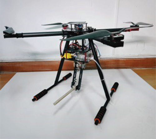
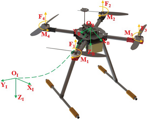
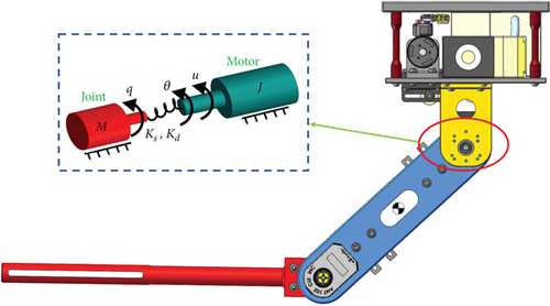
Remark 1. There are uncertainties in the dynamics of the manipulator. According to our precious works [40, 43, 44], a diagonal matrix is used to estimate the above uncertainty.
With Remark 1, Equation (6) can be rewritten as
When the inertia of the manipulator is relatively small with respect to the quadrotor, it is possible to treat the manipulator as an extra mass attached to the quadrotor, and the coupled dynamics are simplified and compensated. Since the quadrotor has a symmetric structure, its inertia matrix can be simplified to the diagonal principal moment of inertia, and the simplified quadrotor dynamics model can be expressed as follows:
3. System Identification Methodology
Remark 2. The models obtained by system identification are mainly used to describe and predict the dynamic behavior of the system, thus playing a key role in the fields of control system design, performance optimization, fault diagnosis, and decision support. With these models, the mechanisms of complex systems can be better understood and system efficiency and reliability can be improved.
3.1. BP Neural Network
The BP neural network is an error backpropagation multilayer feed-forward neural network [45, 46], composed of an input layer, a hidden layer, and an output layer, as illustrated in Figure 4. The network is continuously and iteratively trained using signal forward propagation and error backpropagation to minimize the error function. This process ultimately establishes the relationship between the system’s input and output, achieving system identification.
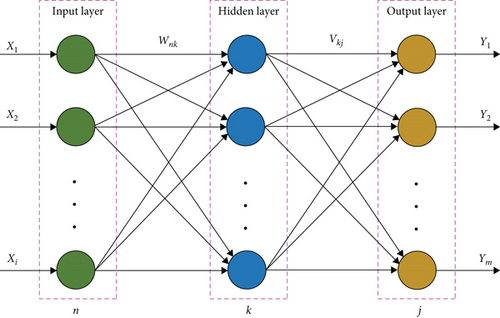
The training steps for the BP neural network are as follows.
Step 1. Initialize the network weights wnk and vkj, and the thresholds a and b.
Step 2. Calculate the output value of the hidden layer neuron qk.
Step 3. Calculate the output of the neurons in the output layer oj.
Step 4. Update the weights.
Step 5. Update the thresholds.
Step 6. Determine whether the algorithm completes the iteration, and return to Step 2 if it does not.
BP neural networks are prone to fall into local optimal solutions during training, especially when dealing with complex, high-dimensional data. In addition, the performance of BP neural networks depends greatly on the initial settings of their parameters. Metaheuristic algorithms can assist BP neural networks to better address their inherent shortcomings by providing an efficient and flexible way to explore the solution space.
3.2. Improved BOA
BOA is a heuristic swarm intelligence optimization algorithm whose core strategy is to simulate butterfly foraging and mating behaviors. Compared to other metaheuristics, BOA achieves a good balance between efficient exploration (global search) and utilization (local search) of the solution space in the algorithm. This helps to find the global optimal solution while avoiding premature convergence to the local optimal solution. It is assumed that all butterflies can emit some kind of scent to make them attract and approach each other, and the scent concentration is related to the fitness function. In this paper, the BOA will be used to optimize the weights and threshold of BP neural network. Here are the steps:
Step 1. Each individual butterfly in the algorithm represents a possible solution, and the initial butterfly population Xid is randomly generated as follows:
Step 2. BOA is characterized by a scent modulation mechanism whereby when the butterfly changes position, its fitness function changes accordingly. The scent information emitted by the butterfly is calculated as
Step 3. In BOA, the random movement of individuals and the movement towards the optimal individual correspond to the global and local search of the algorithm. The movements are described as
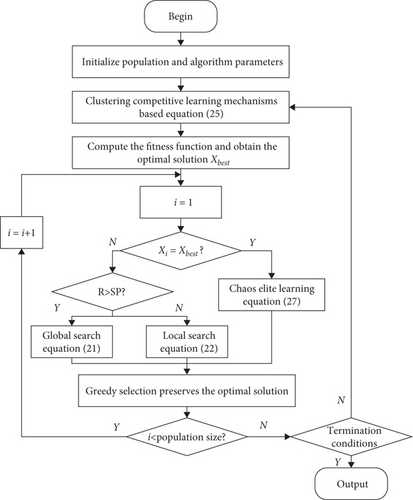
Step 4. Individual butterflies can search for food or mating objects in both global and local search phases. BOA introduces switch probability (SP) to maintain the balance between the two search phases. SP takes the value in the range of [0,1]. For each individual butterfly, if r > SP, end the optimization and assign the optimal solution to the threshold and weights of the BP neural network. Otherwise, a local search is executed according to Equation (22).
3.3. Clustering Competitive Learning Mechanism
Clustering technology can divide a large amount of data into several categories based on certain characteristics, so that data within the same category have the same characteristics. Hence, clustering techniques are an effective way to discover the intrinsic characteristics of data. The overall data information within a certain category can be represented by the clustering center, so that the cluster information can be fully and efficiently utilized to increase the convergence speed of the algorithm. K-mean clustering is one of the typical clustering techniques. It is an unsupervised learning algorithm with a clear structure and simple operation. It mainly includes the following three steps.
Step 1. Randomly select PX1, X2, ⋯, Xm, ⋯, Xg individuals from the current population as initial clustering centers .
Step 2. The distance between the one individual Xm of the population and the clustering center cj(j = 1, 2, ⋯, k) satisfies the condition ‖Xm − cj‖ ⩽ ‖Xm − cp‖; it can be calculated using Euclidean distance:
Step 3. Calculating the new clustering center :
This paper proposed clustering competitive mechanisms based on K-mean clustering. Perform K-mean clustering on butterfly populations PX1, X2, ⋯, Xm, ⋯, Xg, and they will become k category P1, P2, ⋯, Pk, according to Equations (23) and (24) to obtain the clustering centers.
Competitive winners and clustering centers represent the local optimum and mean values in a category, respectively. The second item in Equation (25), where the loser learns from the winner, can make other individuals move towards the local optimal solution, improve their local search capabilities, and speed up the convergence of the algorithm. Those who fail the third item in Equation (25) learn from the clustering center, which can effectively use population information, increase population diversity, and help achieve a balance between global search and local search.
3.4. Chaos Elite Learning Mechanism
The flow of the proposed IBOA is illustrated in Figure 5.
3.5. System Identification Process
The control system of the experimental platform contains a set of avionics, such as flight controller (1), GPS (Global Positioning System) (2), receiver (3), digital radio (4), C610 driver (5), STM32 control board (6), Futaba remote controller (7), and QGC ground station (8), as shown in Figure 6. The C610 driver and the STM32 control board communicate with each other via the CAN bus. The GPS and the digital radio communicate with the Pixhawk flight control via the UART serial port. The Futaba remote control sends remote control signals to the receiver via a 2.4 G signal. The ground station is wirelessly connected to the Pixhawk flight control via a 433 Hz digital radio. The receiver transmits remote control commands to the Pix flight control and the STM32 control board via the SBUS bus. For the motion control, the Pixhawk flight controller sends PWM (pulse-width modulation) signals o the ESC (electronic speed controller) of the quadrotor to control the flight maneuvers. The STM32 control board sends current commands to the C610 driver according to the collected joint signals, and the C610 outputs current to drive the motor according to the current commands, which in turn completes the driving of the manipulator.
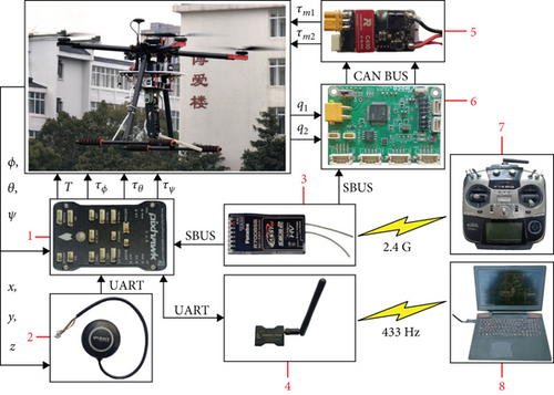
Recall Equations (1), (2), and (7), and the input of the aerial manipulator is , and the output of the aerial manipulator is . The above input and output signals are also the inputs and outputs of the BP neural network model. The process of the IBOA-BP for system identification of the aerial manipulator is given as follows.
3.5.1. Data Collected
The flight operation experiment is divided into two parts: (i) The joints of the cable-driven manipulator are in the original position, and the operator excites the pitch, roll, yaw, and altitude channels of the quadrotor, respectively. (ii) When the quadrotor is hovering, the two joints of the cable-driven manipulator are excited. All the input and output signals are collected by the sensors equipped in the aerial manipulator. More specially, the four control inputs to the vehicle as well as the pose signals are obtained by Pixhawk flight controller with 1 kHz sampling frequency. The joint position and control torque signals are obtained by the STM32 with 1 kHz sampling frequency.
Remark 3. The joint velocity and acceleration cannot be measured directly, if the direct differentiation of the joint position will amplify the noise existing in the measurement, so the analytical method in the literature [48] is used to obtain the angular velocity and angular acceleration, and the specific steps will not be repeated here.
3.5.2. Data Preprocessing
Remark 4. Excessive use of five-point cubic filtering on the raw data can lead to distortion of the data, thus losing the characterization of the raw data. Therefore, the filtering was repeated five times in this experiment.
3.5.3. Data Normalization
3.5.4. Data Back-Normalization
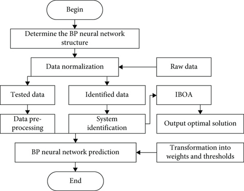
The flow of the proposed cable-driven aerial manipulator system identification algorithm based on BP-IBOA is shown in Figure 7.
4. Result Analysis
4.1. Identification Results
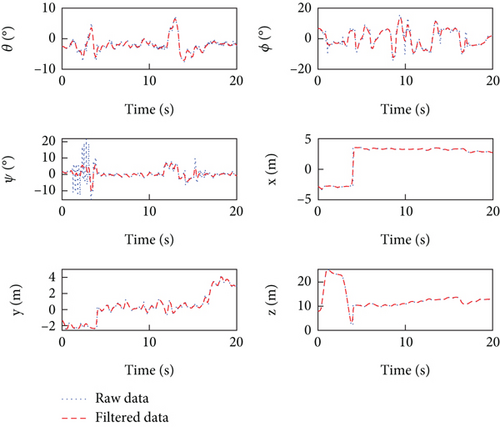
Figures 8, 9, and 10 provide the input and output data of the aerial manipulator system, as well as the raw data after undergoing the five-spot triple smoothing method. The data was sampled over a 20-s period with a sampling frequency of 1 kHz. Notably, the figures clearly illustrate the transformation of the system’s input and output data into a smoother and more consistent form after filtering, which enhances the effectiveness of the system identification algorithm. It is important to emphasize that excessive application of the five-point cubic filtering method can distort the raw data and lead to the loss of essential information. Therefore, in this experiment, a filtering frequency of 10 is selected.
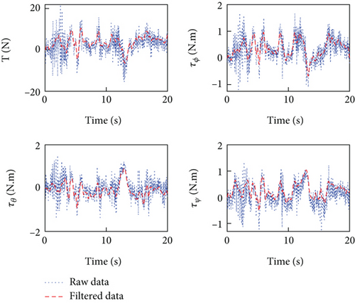
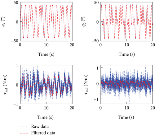
The BP neural network employs the S-type activation function, with 20 nodes in the hidden layer. Training is performed using the Trainlm function, with a maximum of 50 training iterations. The training target is set at 0.003, and the learning rate is 0.01. The weights and thresholds of the BP neural network model are optimized using the IBOA proposed in this paper. To assess the IBOA’s performance, it is compared with the BOA and the chaotic artificial bee colony (CABC) algorithm, with their execution conditions outlined in Table 1. It is important to note that the parameters for CABC are defined in [49, 50].
Remark 5. The proposed system identification method, utilizing the BP neural network with the IBOA, is denoted as Algorithm 1. Similarly, the BP neural network with the BOA is referred to as Algorithm 2, and the one with the CABC algorithm is designated as Algorithm 3.
| Algorithm | Parameters |
|---|---|
| 1 | c = 2, rid = 0.5, r = 0.5, g = 20, SP = 0.8, Tmax = 50 |
| 2 | c = 2, rid = 0.5, r = 0.5, g = 20, SP = 0.8, Tmax = 50 |
| 3 | Np = 20, limit = 20, Tmax = 50 |
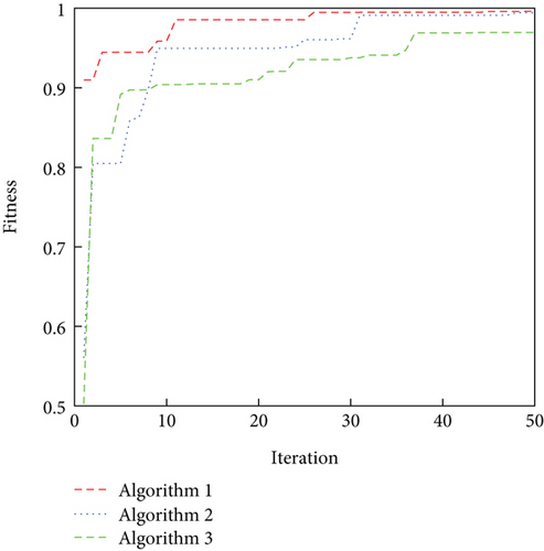
The iteration curves of the three algorithms are shown in Figure 11. As can be seen from the figure, all three algorithms begin to converge at around 10 generations, although Algorithm 1 has the fastest convergence rate. Meanwhile, Algorithm 1 finally obtains an adaptation value of 0.9962, Algorithm 2 is 0.9844, and Algorithm 3 is 0.9684. Furthermore, Algorithm 1 runs for 2.4 s, Algorithm 2 for 3.7 s, and Algorithm 3 for 1.8 s. This shows that compared to the other two algorithms, the IBOA can help the BP neural network to obtain optimal thresholds and weights by fully mining the data. Due to the addition of improved operators, the operational efficiency of IBOA is lower than BOA, but it is still 35.14% higher than CABC. This also proves that IBOA has a better operational framework.
In the system identification process, the first 10s of filtered input and output data are selected as the excitation signal, and three algorithms are used to fit the dynamics model of the aerial manipulator, respectively. Then, the filtered input data of the latter 10s is utilized as the excitation signal to activate the identified dynamics model. The output signal produced by the model is compared with the filtered input data of the latter 10s output data. Figures 12 and 13 show the identified results by the three algorithms. It can be seen that the predicted values from all three identification algorithms track the actual data, but it is clear that the predictions from Algorithm 1 track the actual data the best.
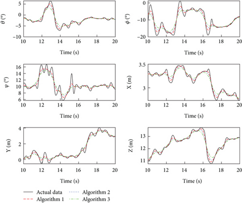
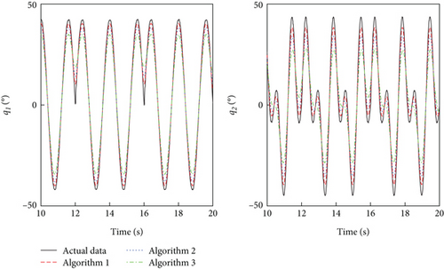
Table 2 shows the correlation coefficient of the three identified algorithms. It can be seen that the three algorithms can all obtain good correlation coefficient. The correlation coefficient of IBOA-BP is higher than that of BOA-BP and CABC-BP. For example, the correlation coefficient of output θ of IBOA-BP is 3.86% and 9.96% higher CABC-BP and BOA-BP, respectively. The correlation of output X of IBOA-BP is 4.25% and 11.87% higher CABC-BP and BOA-BP, respectively. The correlation of output q1 of IBOA-BP is 0.11% and 0.51% higher CABC-BP and BOA-BP, respectively. The results show that IBOA-BP has a stronger system identification capability and is able to obtain more accurate dynamics models using input and output data. In addition, the correlation coefficient of the robotic arm output is significantly better than that of the quadrotor output. This is due to the fact that the manipulator uses joint space control and is not subjected to as much perturbation as the quadrotor.
| Output | Algorithm 1 | Algorithm 2 | Algorithm 3 |
|---|---|---|---|
| θ | 0.9661 | 0.9288 | 0.8699 |
| ϕ | 0.9671 | 0.9199 | 0.8671 |
| ψ | 0.8706 | 0.8023 | 0.7327 |
| X | 0.9526 | 0.9121 | 0.8515 |
| Y | 0.9769 | 0.9562 | 0.9199 |
| Z | 0.9922 | 0.9815 | 0.9600 |
| q1 | 0.9991 | 0.9980 | 0.9940 |
| q2 | 0.9914 | 0.9678 | 0.9024 |
4.2. Model Validation
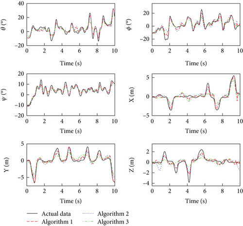
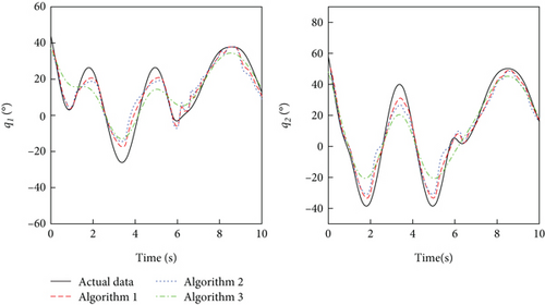
For system identification, model validation is also required to verify the validity of the identified model. Another set of experimental data will be used to validate the effectiveness of the identified model. We collected 10s of flight data, which are also preprocessed using the five-point triple filtering method. Then, the processed input data are used as excitation signals to stimulate the identified model, and the predicted output data are compared with the actual output data. As shown in Figures 14 and 15, the predicted output data by three algorithms are in better agreement with the experimental data and basically match up. Furthermore, the correlation coefficient between the predicted output and actual output is listed in Table 3. It is evident that the correlation coefficients of the output state quantities are worse than those in Table 2, especially for the Z channel. However, the dynamics models obtained by the three algorithms still provide a good description of the dynamic response of the cable-driven aerial manipulator. More specially, the dynamics model obtained by the IBOA-BP algorithm is still by superior to the models obtained by the other two algorithms. This indicates the robustness and accuracy of the dynamics model obtained through IBOA-BP algorithm.
| Output | Algorithm 1 | Algorithm 2 | Algorithm 3 |
|---|---|---|---|
| θ | 0.9157 | 0.8520 | 0.8946 |
| ϕ | 0.9685 | 0.8874 | 0.9239 |
| ψ | 0.9755 | 0.8955 | 0.8497 |
| X | 0.8630 | 0.8252 | 0.7643 |
| Y | 0.9288 | 0.9210 | 0.8436 |
| Z | 0.7977 | 0.7993 | 0.5959 |
| q1 | 0.9696 | 0.9359 | 0.8874 |
| q2 | 0.9913 | 0.9785 | 0.9735 |
In addition, the identified models of an aerial manipulator generated by data analysis and mathematical modeling are often a simplified approximate description. Such models usually fail to fully capture the dynamic behavior of real and complex systems because they may not account for nonlinearities, coupling effects, and unmodeled dynamic properties. Therefore, model uncertainties need to be fully considered in control and decision-making strategy development, and appropriate control strategies need to be employed to cope with these discrepancies to ensure the reliability and performance of the aerial manipulator.
Remark 6. The dynamics model of the cable-driven aerial manipulator in this paper should include the dynamic response of the controller. The controller used in this paper is a PID (proportion integration differentiation) controller, which is a commonly used controller for robotic systems. In order to exclude the influence of controllers on the identification results, the same set of controllers and the same set of controller parameters were used for the two previous and two previous identifications.
5. Conclusions
This paper presents a new method combining BP neural network technique and improved BOA for system identification of an aerial manipulator equipped with a cable-driven manipulator. It is found that the algorithm proposed in this paper outperforms BOA-BP and CABC-BP in terms of identified accuracy, robustness, and stability. Thanks to IBOA, the BP neural network is able to describe the dynamic behavior of the aerial manipulator faster and better. Meanwhile, the designed cable-driven aerial manipulator prototype is also proved to be effective and controllable through the identified experiments.
In the future, another advanced methods will be developed for the system identification of the robotic systems. The identified objects will also be extended from aerial manipulators to other types of robots, such as space manipulators, underwater manipulators, and ground mobile manipulators. In addition, we will explore novel controllers to achieve stable control of these identified models.
Conflicts of Interest
The authors declare no conflicts of interest.
Funding
This paper was supported by the National Natural Science Foundation of China (Nos. 52375101 and 52005231).
Open Research
Data Availability Statement
The data of simulation can be provided if necessary.


