Numerical Investigation on the Indicated Mean Effective Pressure and Integral Heat Release Rate Variations under Different Key Operating Parameters of a Spark-Ignited Free Piston Engine Generator
Abstract
Free-piston engine generator is a new type of hybrid power device and is regarded as the next-generation energy conversion device which can replace the traditional internal combustion engine. This paper focused on the combustion stability and combines experimental results to study the key factors affecting the stability of the free-piston engine, such as ignition time, intake pressure, equivalence ratio, and operating frequency. The simulation results showed that as the ignition advance angle increased, the indicated mean effective pressure increased significantly and the coefficient of variation of the indicated mean effective pressure was effectively reduced from 15.55% to 1.02% as the advance in ignition time from −15 to −30°ECA. When the intake pressure was increased to 1.2 bar, the average value of indicated mean effective pressure reached about 5.15 bar. When the equivalence ratio was in the range of 1.0–1.4, the coefficient of variation of the indicated mean effective pressure can be kept below 10%. The indicated mean effective pressure decreased monotonically from 4.79 to 3.62 bar, and the coefficient of variation increased by five times as the engine speed increased as the engine speed increased from 1,000 to 2,500 RPM.
1. Introduction
1.1. Background
Emission levels, fossil fuel depletion, and increased prices of underground fuels are the main influential forces for researchers to find out an alternating way for emission reduction and making the engine independent from fossil and imported fuels [1, 2]. The ongoing depletion of oil resources and the growing environmental concerns arising from automobile emissions have made hybrid power an inevitable developmental trend [3, 4]. FPEG is directly coupled by the free-piston internal combustion engine and the linear motor and is regarded as the next generation energy conversion device which can replace the traditional internal combustion engine [5, 6]. Compared with conventional engines, FPEG eliminates the complex crank connecting rod mechanical, and the high-temperature and high-pressure gas in the combustion cylinder drives the motor to reciprocate in a straight line to generate electricity. The free-piston engine has the advantages of simple structure [7], variable compression ratio [8], high volumetric power density [9], low friction loss, and easy modular arrangement and has been a hot research topic in the field of internal combustion engines internationally.
1.2. Literature Review
Since the late 1990s, the University of West Virginia has been engaged in the design and development of a free-piston internal combustion power generation system. The first prototype utilized reflux scavenging and inlet injection and employed a dedicated starting coil to aid in ignition [10]. The cylinder diameter of the prototype free-piston internal combustion engine was 36.5 mm, and the maximum design stroke was 50 mm. The experimental results showed that the prototype involved completing a brief reciprocating motion, with an average piston speed of 2.37 m/s, an operating frequency of 23.1 Hz, and a maximum power generation of 313 W [11, 12]. However, the system experienced frequent misfires. Atkinson et al. [13] established a complete working cycle simulation model, and the simulation results showed that the peak pressure in the cylinder increased with the decrease of the combustion duration, and the increase in the peak pressure in the cylinder led to an increase in the operating frequency, and the compression ratio of the system would increase at the same time. The operating frequency of the system depends on the quality of the moving parts, and the reduction in the mass of the moving parts results in a decrease in the operating frequency of the system [13]. Houdyschell [14] designed a two-stroke dual-cylinder dual-piston FPEG compression ignition prototype. And the prototype uses a high-pressure common rail for fuel supply, and fuel is injected directly into the cylinder through a direct injection injector. The results revealed that the homogeneous compression combustion mode increased the indication efficiency of the system, but the stability of the system was considerably sensitive to various parameters, rendering control difficulties [15].
Mikalsen et al. [16] proposed a piston motion control method based on the top dead center prediction, and the engine fuel injection quantity is based on the predicted piston top dead center position in the compression stroke rather than the actual measurement. The simulation results showed that the control method can reduce the time delay of the controller and accelerate the response speed of the system [17]. Jia et al. [18] established a MATLAB model which is validated by experimental data to simulate the starting and stable operation of a dual-cylinder type FPEG. The oscillating start strategy was successfully realized, and the source of interference was qualitatively analyzed based on the simplified dynamic model [19]. As evidenced through the in-depth research on the combustion and emission of FPEG, compared with traditional crank link engines, the stable operation of FPEG is more difficult and is easily affected by numerous critical factors such as intake, ignition, and operating frequency. The stability of FPEG operation is closely associated with the cyclic variation of the combustion process in the free-piston engine.
Since the 1970s, a large number of scholars have investigated the cyclic variation of spark engines, and the correlation between cyclic variation, engine emissions, and performance has been confirmed [20, 21]. Lyon [22] conducted an experimental study on a commercial four-cylinder engine, with the results confirming that the cycle variation could be eliminated and the economy of the engine could be increased by 6%. Wang and Ji [23] conducted an experimental study on the cyclic variation characteristics of a hydrogen-rich gasoline engine under different working conditions. The experimental results indicated that the coefficient of variation of the indicated mean effective pressure decreased obviously with the increase in hydrogen ratio [24]. At a fixed speed and inlet pressure, when the inlet hydrogen volume fraction increased from 0% to 4.5%, the relevant excess air ratio of the engine lean combustion limit increased from 1.45 to 2.55 [25]. Zhao et al. [26] evaluated the cyclic variation in the combustion process of a hydraulic free-piston engine (HFPE). The coefficient of variation and correlation coefficient were calculated, and the results showed that the cyclic variation of HFPE was primarily caused by the special motion law of the piston [26]. Such results provided a theoretical basis for controlling the cyclic variations of the system [27]. From the actual operation of the engine, cyclic changes in external conditions are almost inevitable. During the intake process, the pressurization and filtration of the air will affect the intake state [28, 29], resulting in changes in the initial gas conditions of each cycle, which in turn will lead to cycle changes in combustion.
Previous studies have indicated that an increase in cyclic variation can negatively impact vehicle comfort, as well as result in elevated exhaust emissions and reduced thermal efficiency. Thus, reducing cyclic fluctuations is of great significance to improving engine performance. Free-piston engine operates different from traditional engines, since the piston motion is not constrained by the crankshaft connecting rod. So, for free-piston engines, cyclic fluctuations are a bigger challenge. However, there are currently few studies on the influencing factors and change patterns of FPEG cycle variation.
1.3. Aims and Methodology
In this research, a complete dual-cylinder type FPEG system test bench was established, a three-dimensional FPEG model was constructed using the computational fluid dynamics (CFD) simulation software CONVERGE, and the model was calibrated through the experimental results. Firstly, the periodic variation of 50 consecutive cycles when the FPEG system works in dual-cylinder and single-cylinder mode is explored. The cyclic variation of the system under the single-cylinder operation mode and dual-cylinder working mode was investigated. Then, the effects of key parameters such as ignition time, intake pressure, equivalence ratio, and operating frequency on the cyclic variation of the combustion process of the FPEG system were investigated. This paper aims to provide a basis reference for the efficient and stable operation of the FPEG system.
2. FPEG Configuration and Experimental Setup
2.1. FPEG Configuration
The dual-cylinder type FPEG prototype which is designed by our present research group adopts a two-stroke reflux scavenging method for air exchange and uses gasoline fuel. The prototype design parameters and detailed specifications are shown in Table 1. The property of the fuel used in this study is showed in Table 2 [30, 31].
| Specifications | Values | Unit |
|---|---|---|
| Ignition method | Spark ignition | — |
| Engine displacement | 130 | cc |
| Design stroke | 60 | mm |
| Cylinder bore | 52.5 | mm |
| Compress ratio | 8 | — |
| Fuel type | Gasoline | — |
| Intake boosting | 1.1 | bar |
| Fuel delivery system | Port injection | — |
| Property | Unit | Gasoline |
|---|---|---|
| Chemical formula | — | CnH1.87 n |
| Molecular weight | Kg kmal−1 | 114.24 |
| Equivalence ratio ignition lower limit in NTP air | — | 0.7 |
| Flammability limits in air at NTP | %vol. | 1.4–7.6 |
| Flammability limits (λ) | — | 1.51–0.26 |
| Flammability limits (ϕ) | — | 0.66–3.85 |
| Minimum ignition energy in air | mJ | 0.28 |
| Autoignition temperature at STP | °C | 247–280 |
| Mass lower heating value at STP | kJ/kg | 44,500 |
| Density of gas at STP | kg/m3 | 750 |
| Diffusivity in air | cm2/s | ~0.07 |
| Octane number | — | 87 |
| Volumetric lower heating value at NTP | kJ/m3 | 195,800 |
| Stoichiometric air-to-fuel ratio | kg/kg | 14.7 |
| Volumetric fraction of fuel in air, λ = 1 | — | 0.0165 |
| Laminar burning velocity | m/s | 0.45 |
| Laminar burning speed in NTP air | cm/s | 37–43 |
| Quenching distance in NTP air | cm | 0.2 |
| Flame temperature in air | K | 2,470 |
- NTP denotes normal temperature (293.15 K) and pressure (1 atm). STP denotes standard temperature (0°C) and pressure (1 bar).
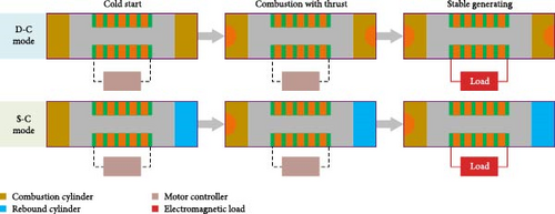
During the stable generating process, the mover assembly which is composed of electric motor mover, pistons, and connecting rods moves from the top dead center of the left combustion chamber to the right side under the pressure of high-pressure gas. The permanent magnet fixed on the mover assembly passes through the inside of the coil, and the coil cuts the magnetic field line to generate induced electromotive force so as to output electric energy. The piston moves to the right and passes through the left exhaust port of the left cylinder. The left cylinder begins to scavenge until the piston moves to the left and passes through the left exhaust port again. At the same time, the fuel–air mixture in the right combustion chamber is compressed by the piston as it moves toward the top dead center of the opposite side. Upon reaching the predetermined ignition position, the mixture is ignited. The high-pressure gas propels the piston assembly toward the left until it reaches the top dead center of the opposite side, thereby completing a full working cycle.
2.2. Experimental Setup
The FPEG prototype working mode and working process is shown in Figure 1. According to the experimental requirements of the FPEG system, relevant sensors and analysis instruments were arranged in corresponding positions for accurate measurement. The technical parameters and measurement accuracy of the sensor are shown in Table 3 [32, 33].
| Instrument | Measured parameters | Range | Accuracy |
|---|---|---|---|
| Hall position sensor | Piston position | — | ±25 μm |
| Air–fuel ratio analyzer | Air–fuel ratio | 3.99–500.0 | ±9.1%A/F |
| Gas pressure sensor | Gas pressure | 0–250 bar | ±0.3%FS |
| Intake air flow sensor | Intake air flow | 6–125 m3/hr | ±1.0% |
| Voltage sensor | Generation voltage | 0–1,000 V | ±1.0% |
| Current sensor | Generation current | 0–300 A | ±3.0% |
The intake compression system used in the present study mainly included a screw air compressor (DHF-10PM), cast steel gas storage tank (1.58 MPa), freeze dryer (DHF-10), and air filter (DHF-QPS). The nominal volume flow rate of the air compressor was 0.54–1.35 m3/min, and the rated pressure was 0.8 MPa, which was enough to meet the intake and pressurization requirements of the dual-cylinder FPEG system. The PMAC motion control system was adopted for the test control system of the FPEG prototype, and the control parameters are the injection position, ignition position, and motor force. The PXI Express data acquisition system of National Instruments was adopted for the test data acquisition module and was equipped with an NI PXIe-6356 data acquisition card, including eight analog input channels and two analog output channels. The sampling rate was 1.25 MS/s. The air–fuel ratio analyzer is HORIBA MEXA-730λ, which can achieve a measurement accuracy of ±0.1 A/F. For power analysis, the YOKOGAWA DL950 power analyzer is used to monitor and analyze the voltage and current values of each phase in the three-phase circuit in real-time through the voltage difference probe and the current probe.
3. Modeling and Validation
3.1. Data Processing and Analysis
3.2. Multiphysics Coupling Simulation System
Figure 2 shows the multiphysics computing platform that combines simulation and experimentation of the FPEG system. Based on the dual-cylinder spark-ignited FPEG prototype developed by our research group, this paper establishes the FPEG multiphysics field coupling simulation experiment bench. The zero-dimensional computing model is coupled with the three-dimensional computing model. The coupling simulation system consists of a MATLAB model for calculating the dynamic characteristics of the piston motion and a three-dimensional CFD simulation model for calculating the working process in combustion cylinder. The piston displacement calculated by the kinematic model is used as the input of the CFD model. The FPEG prototype provides boundary conditions and engine parameters for the simulation model.
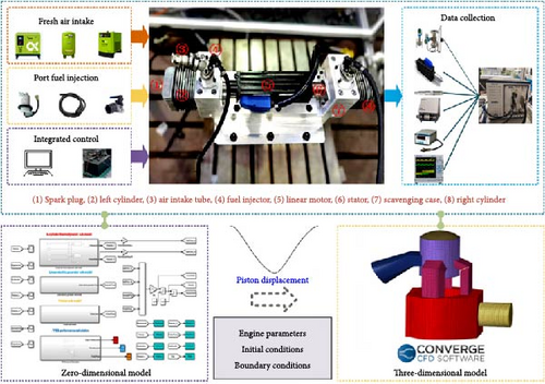
In order to study cycle to cycle variation of the free-piston engine, 10 stable and continuous cycles were selected from the calculation results of the CFD simulation model. The parameter settings of the initial conditions and boundary conditions in the calculation process are based on the experimental results of the physical prototype, and several parameters are set according to the empirical values. The specific boundary condition parameters are shown in Table 4. The reaction mechanism selected by the model is shown in Table 5.
| Parameter | Values | Unit |
|---|---|---|
| Intake pressure | 1.1 | bar |
| Intake temperature | 300 | K |
| Exhaust pressure | 1 | bar |
| Exhaust temperature | 500 | K |
| Cylinder head temperature | 550 | K |
| Piston face temperature | 550 | K |
| Cylinder wall temperature | 450 | K |
| Description | Model |
|---|---|
| Turbulent flow model | k-zeta-f model |
| Combustion model | ECFM model |
| Heat transfer model | Han–Reitz model |
| NOx formation mechanism | Extension Zeldovitch model |
| Ignition model | Spherical selection module |
3.3. Model Validation
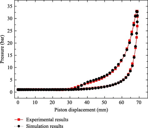
The results of the experiment and simulation were compared, so as to verify the effectiveness of the established simulation model. Figure 3 shows the comparison of the simulation data and experimental data under the same boundary conditions and operating conditions. An observation can be made that in the compression stroke and high-pressure stage, the simulation data and experimental data are basically consistent. The maximum cylinder pressure of the simulation is 33.69 bar, the maximum cylinder pressure of the experiment is 33.46 bar, and the error is about 0.7%. The maximum error value is within 5%, indicating that the accuracy of the established model met the research requirements.
3.4. Grid Independence Verification
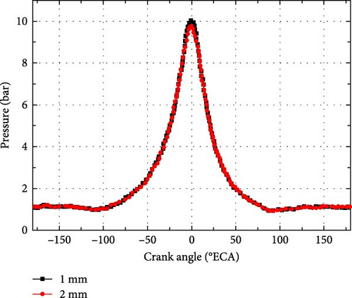
In order to verify the numerical simulation model, the sensitivity of the proposed numerical simulation model to different mesh sizes has been analyzed by our previous research [35]. Under the condition of noncombustion, 1 × 1 × 1 mm and 2 × 2 × 2 mm grids were applied to simulate the in-cylinder working process of the dual-cylinder free-piston linear motor. The simulation results are demonstrated in Figure 4. It can be clearly seen that there are few differences in the in-cylinder pressure curve among the grids with the size of 1 × 1 × 1 mm and 2 × 2 × 2 mm. In order to ensure the stability and accuracy of numerical calculations, a fully orthogonal hexahedral grid with a basic size of 2 mm is used for global calculations. Taking into account the dramatic changes in temperature gradient, velocity gradient, and pressure gradient in the local area, the size ratio of adjacent grids is less than 2 × 2 × 2 mm.
4. Results and Discussion
4.1. Experimental Data and Analysis
Figure 5 shows continuous 50-cycle piston displacement and in-cylinder pressure changes collected from experimental prototype. However, from the current experimental results, there is still a large space for improvement in FPEG performance. As can be seen from Figure 5, the peak pressure of the engine in the single-cylinder working mode is higher, and the fluctuation is smaller than that in the dual-cylinder working mode. Compared with the dual-cylinder working mode, the free-piston cylinder in the single-cylinder working mode has more sufficient ventilation time.


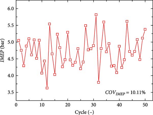
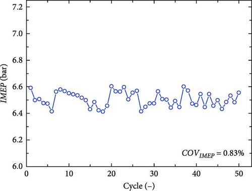
The periodic variation of 50 consecutive cycles when the FPEG system works in dual-cylinder and single-cylinder mode is explored. Based on the results shown in Figure 6, it can be inferred that the single-cylinder working mode of the free-piston engine generator is more stable than the dual-cylinder working mode. The 10.11% COVIMEP value for the dual-cylinder working mode is much greater compared to the 0.83% COVIMEP value for the single-cylinder working mode.
4.2. Cyclic Variation under Different Ignition Time of the Simulation Results
Ignition timing is the concept of ignition advance angle in traditional internal combustion engines. This ignites the combustible mixture in the combustion chamber. From the ignition moment until the piston reaches the compression top dead center, the angle the crankshaft rotates during this period is called the ignition advance angle. For example, if the ignition occurs 15°ECA before the top dead center, we call the ignition time of this cycle −15°ECA.
Figure 7(a) shows the IMEP changes with the number of cycles. It can be seen from the simulation results that the IMEP increased significantly with the increase in ignition advance angle. With the advance in ignition time from −15 to −30°ECA, the IMEP increased from 3.29 to 5.56 bar, an increase of 69%. With the advance in ignition time, the mixture burned rapidly, and the combustion duration was significantly shortened, as shown in Figure 8.
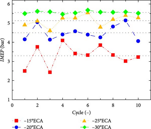
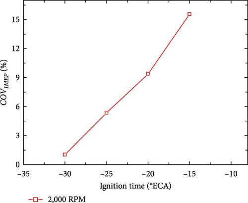

Figure 7(b) shows the COVIMEP changes under different ignition times. The results indicated that an earlier ignition time had a notable positive impact on the COVIMEP of the free-piston engine, which was primarily due to the fact that in the early stage of combustion, although the fire core is still small, it can be removed from the spark plug area by large-scale flow in the cylinder. This phenomenon occurred in a random manner and had a significant impact on the subsequent propagation of combustion, resulting in cyclic changes. For FPEG, early ignition promoted the rapid and complete combustion of the fuel–air mixture, and the combustion duration was significantly shortened.
Figure 8 shows the relationship between the integral heat release rate and the equivalent crank angle under different ignition time. The integral heat release rate is defined as the percentage of the integral heat release of a certain crank angle to the total heat release of the whole combustion process. Additionally, the flame propagation (CA10-90) period is also based on the integral heat release, which is defined as the crank angle duration from 10% to 90% of the total fuel heat release from the spark plug ignition. As shown in Figure 8, CA10-90 was shortened after early ignition because more fuel was burned around the top dead center as the ignition time advanced. When the ignition was advanced, COVIMEP was effectively reduced from 15.55% at −15°ECA to 1.02% at −30°ECA. Shortening the combustion duration is beneficial for reducing the cyclic variation of the free-piston engine.
Figure 9 shows the changes of in-cylinder gas peak pressure (Pmax) and its cyclic variation coefficient (COVPmax) at 2,000 RPM and different ignition times. Under the same conditions, COVPmax increased first and then decreased with the delay in ignition time.
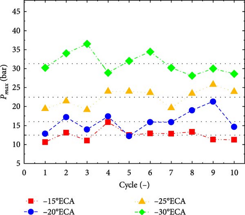
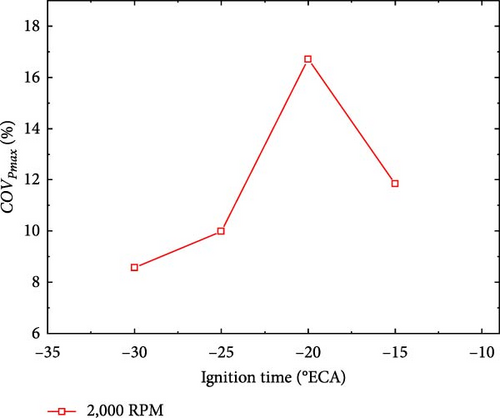
When the ignition time is delayed, owing to the decrease in combustion temperature and pressure, the combustion duration of the mixture in the cylinder would inevitably be prolonged. Therefore, COVIMEP increased significantly with the delay in excessive ignition time. In contrast, peak cylinder pressure is affected by both combustion and piston motion. An observation can be made from Figure 9(a) that in the case of ignition delay, the influence of piston motion on peak cylinder pressure became increasingly obvious with the further extension of combustion time. Because the pressure rise caused by piston motion was more stable than that caused by combustion at a constant engine speed, COVPmax decreased again when the ignition was delayed.
4.3. Cyclic Variation under Different Intake Pressures of the Simulation Results
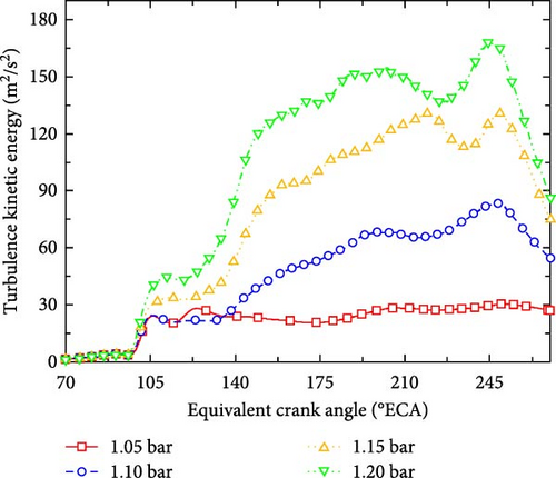
Figure 10 shows the evolution of the indicated mean effective pressure with the number of cycles under different intake pressures at the same ignition time and engine speed. The IMEP increased with the increase in intake pressure. When the intake pressure increases from 1.05 to 1.20 bar, the average value of IMEP reached to 5.15 bar. When the intake pressure increased, the quality of the fuel entering the cylinder increased, the flow of the working fluid in the cylinder is enhanced, and the turbulent kinetic energy increased, as shown in Figure 10. When the intake pressure increased from 1.05 to 1.20 bar, the peak value of turbulent kinetic energy increased from 28.1 to 244.7 m2/s2. The increase of turbulent kinetic energy led to the acceleration of fuel evaporation rate and the more uniform mixing of the mixture. In addition, it can be seen from Figure 10(b) that under different intake pressures, COVIMEP did not change much and remained between a small value. It indicates that FPEG could operate stably and continuously under different intake pressures.
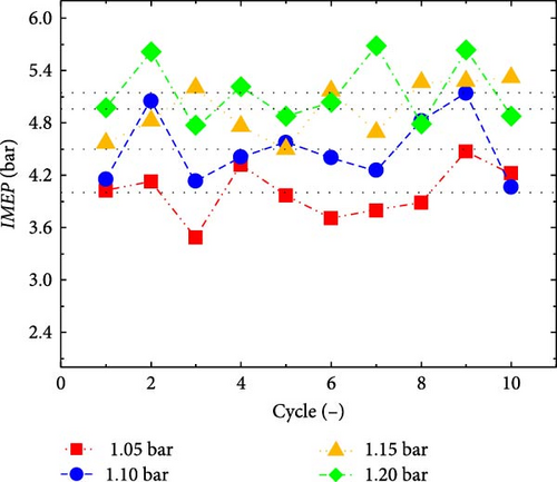
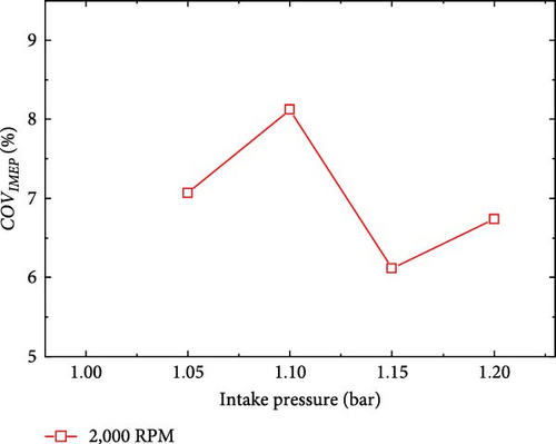
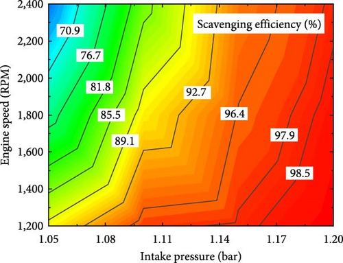
In contrast, the cyclic variation of FPEG is more obviously affected by the ignition time. Cyclic variation is mainly caused by the difference in ignition and combustion process in each cycle. The most significant influencing factors are mixture composition fluctuation and gas motion state fluctuation. Figure 11 shows the scavenging efficiency of FPEG under different intake pressures and frequencies. Evidently, except for some extreme cases, the scavenging efficiency of FPEG was maintained at a good state, and the composition of the mixture in the cylinder had little fluctuation. At the same time, the ignition time and ignition energy did not change, which ensured that the cyclic variation of FPEG under different inlet pressures was not large.
4.4. Cyclic Variation under Different Equivalence Ratios of the Simulation Results
The equivalence ratio, also known as “fuel coefficient” or “remaining oil coefficient,” is the ratio of the theoretical amount of air required for complete combustion to the actual amount of air supplied when fuel is burned.
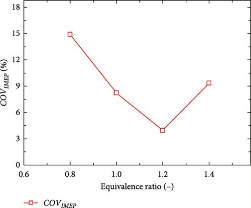
Figure 12 shows the IMEP and COVIMEP change under different equivalence ratios. It can be seen from the simulation results that the equivalence ratio has a great influence on both IMEP and COVIMEP. When the equivalence ratio is 1.2, the average value of IMEP is the largest.
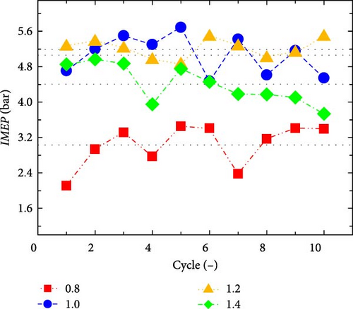
From Figure 13, it can be observed that when the equivalence ratio decreased from 1.2 to 0.8, the combustion heat release process is significantly prolonged, resulting in the whole combustion process deviating from the top dead center. During this process, the combustion duration is extended by 8°ECA. The free-piston engine released a large amount of heat in a short time, which promoted the continuous increase of in-cylinder pressure.

Another noteworthy trend is that the COVIMEP can be kept below 10% when the equivalence ratio is around 1.0. However, as the concentration of the mixture further dilutes, the COVIMEP of the engine increased sharply. When the equivalence ratio dropped to 0.8, COVIMEP increased significantly to 14.9%, which means that under lean combustion conditions, the probability of partial combustion or even misfire of the engine will be greatly increased. For the FPEG, any factor that slows down the combustion process will increase its cyclic variation. Therefore, in order to better run the stability, the equivalence ratio should be selected in a relatively dense range (1.0–1.2).
4.5. Cyclic Variation under Different Engine Speeds of the Simulation Results
Figure 14 shows the IMEP and COVIMEP change under different engine speed. The IMEP decreased from 4.79 to 3.62 bar as the engine speed increased from 1,000 to 2,500 RPM. This reduction is mainly due to the engine scavenging efficiency decreased when the engine speed increases (Figure 15), and the residual gas in the cylinder increased. The residual gas coefficient caused the combustion rate to decrease, as shown in Figure 16.
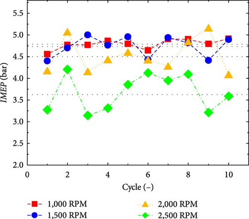
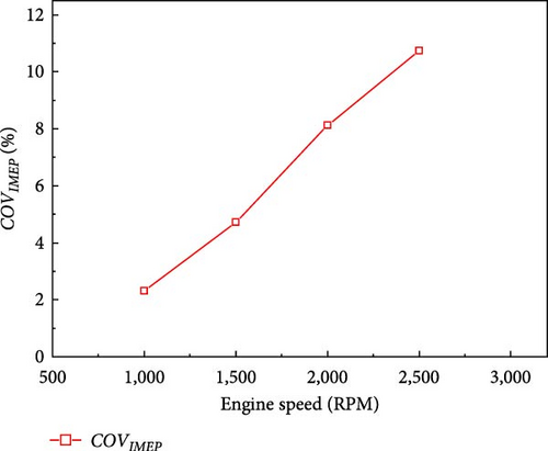
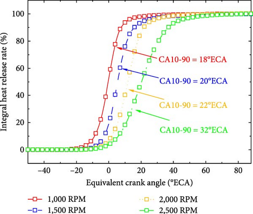
The COVIMEP of FPEG under different speeds is depicted in Figure 14(b). The coefficient of variation increases as the engine speed increases, with the COVIMEP reaching 2.3% and exceeding 10% at 2,500 RPM. It can be seen from Figure 14 that when the ignition timing is fixed, the heat release process is significantly extended with the increase in speed, leading to the deviation of the whole combustion process from top dead center. When the speed increased from 1,000 to 2,500 RPM, the rapid combustion duration is prolonged by 14°ECA. More heat release processes occurred on the power stroke, resulting in the reduction of combustion efficiency, which also explains the decrease in IMEP.
5. Conclusion
- (1)
The single-cylinder working mode of the free-piston engine generator is more stable than the dual-cylinder working mode. The 10.11% COVIMEP value for the dual-cylinder working mode is much greater compared to the 0.83% COVIMEP value for the single-cylinder working mode.
- (2)
With the increase in ignition advance time, the average IMEP value increased significantly. When the advance in ignition time increases from −15 to −30°ECA, the average IMEP increased from 3.29 to 5.56 bar, an increase of 69%. With the advance in ignition, the COVIMEP is effectively reduced, and the COVIMEP value decreased from 15.55% at −15°ECA to 1.02% at −30°ECA.
- (3)
When the intake pressure increases from 1.05 to 1.2 bar, the average value of IMEP reached about 5.15 bar, and the peak value of turbulent kinetic energy increased from 28.1 to 244.7 m2/s2. The increase of turbulent kinetic energy led to the acceleration of fuel evaporation rate and the more uniform mixing of the mixture.
- (4)
When the equivalence ratio is 1.2, the average value of IMEP is the largest. At this time, the combustion speed in the cylinder is fastest. When the equivalence ratio is greater than 0.8, COVIMEP can be kept below 10%, which means that FPEG can operate stably. As the concentration of the mixture further dilutes, the COVIMEP of the engine increased sharply. To achieve better operational stability, the equivalence ratio should be selected in a relatively dense range (1.0–1.2).
- (5)
As the engine speed increased, the average value of IMEP decreased monotonically from 4.79 to 3.62 bar, a decrease of about 25%. When the speed increased from 1,000 to 2,500 RPM, the rapid combustion duration is prolonged by 14°ECA. Such results indicate that the engine operation became more unstable at higher speeds.
Nomenclature
-
- °ECA:
-
- Equivalent crankshaft angle
-
- CA:
-
- Crankshaft angle
-
- CFD:
-
- Computational fluid dynamics
-
- COV:
-
- Coefficient of variation
-
- D-C mode:
-
- Dual-cylinder working mode
-
- FPEG:
-
- Free-piston engine generator
-
- HFPE:
-
- Hydraulic free-piston engine
-
- IMEP:
-
- Indicated mean effective pressure
-
- NTP:
-
- Normal temperature (293.15 K) and pressure (1 atm)
-
- S-C mode:
-
- Single-cylinder working mode
-
- STP:
-
- Standard temperature (0°C) and pressure (1 bar).
Conflicts of Interest
The authors declare that they have no conflicts of interest.
Acknowledgments
This work is funded by the Chinese Government, and we thank the financial sponsors.
Open Research
Data Availability
Data will be made available on request.


