Research on SiC Speed Controller for High-Voltage Distributed Electric Propulsion System
Abstract
The shift towards green aviation necessitates the adoption of all-electric aircraft, marking an essential trend in the aviation industry. Distributed propulsion systems enhance aircraft flexibility and reliability, synchronously reducing performance demands and costs of single propulsion units compared to centralized propulsion system. The high reliability and lightweight characteristics of brushless DC motors have made them increasingly popular in distributed propulsion systems. Despite its advantage which helps to build efficient aircraft aerodynamic layout, there are more cables in the distributed propulsion system, which accounts for most of the weight of the aircraft. To address this, all-electric aircraft utilizes high-voltage power supply to reduce the current, so it uses SiC MOSFETs as power devices to improve its efficiency and heat dissipation. The speed controller in all-electric aircraft determines the efficiency and reliability of the propulsion unit. However, the traditional high-voltage speed controller poses challenges for aircraft maintenance because of high cost. Therefore, this paper emphasizes the significance of designing a low-cost, high-performance speed controller for all-electric aircraft. Challenges such as circuit interference, battery voltage fluctuation, and sampling noise affecting the high-voltage controller during operation are solved, respectively. First, to address the likelihood of mutual interference in the bridge arm, a self-bootstrapping voltage reduction drive mode is designed to turn off SiC MOSFET and enhance circuit anti-interference. Second, to solve the challenge of wide battery voltage fluctuation range and inconsistent controller output, an adaptive pulse width modulation (PWM) regulation mode for battery voltage is proposed, ensuring stable controller output. Finally, to counteract the impact of the comparator threshold on zero-crossing sampling, an electrical angle delay method based on delay compensation is designed to improve the efficiency of the brushless DC motor during operation. Experimental results show that the three solutions proposed in this paper are helpful to improve the anti-interference, stability, and efficiency of the controller in the high-voltage distributed electric propulsion system and contribute to reduce the cost and weight in the propulsion unit.
1. Introduction
Currently, aviation accounts for 2.4% of global carbon dioxide emissions. Achieving net zero carbon emissions by 2050 means a reduction of 21.2 billion tonnes of carbon emissions between now and then [1]. Electrification represents an inevitable and cutting-edge trend in atmospheric flight. Current technological maturity has reached the state that supports the practical application of small electric aircraft. Electrification of commercial aircraft is likely to become a reality in the next decade.
The power propulsion system is the core component of an all-electric aircraft, responsible for providing the necessary power and propulsion. Compared to centralized propulsion, distributed propulsion distributes multiple propulsion units in different locations on the aircraft, enhancing its flexibility in flight. As a result, this approach enables a simpler structure during design, pays lower costs during operation and maintenance, and reduces noise during use [2].
The components of the power propulsion system are shown in Figure 1. The brushless DC motor, famous for its high power density, long service life, and rapid response, is generally chosen to drive the propeller to provide propulsion for the all-electric aircraft. Compared to sensor control, sensorless control does not require an external position sensor, which reduces the maintenance cost. The sensorless control is generally selected to run the brushless DC motor in the all-electric aircraft. In order to reduce the weight of the cable and meet the lightweight requirements of the aircraft components, the all-electric aircraft uses a high-voltage power supply to reduce the current. [3] shows that SiC MOSFETs exhibit lower heat generation and power loss during operation compared to Si MOSFETs, resulting in higher efficiency. Consequently, SiC MOSFETs are highly suitable as power devices to drive the motor under high voltage.
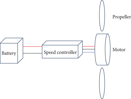
At present, the open-loop controller, known for its low cost and simple structure, can be applied in various flight control scenarios. The control strategy of the speed controller directly affects the power propulsion system’s efficiency and performance [4]. Typically, a simple sensorless six-step reverse control strategy is used for brushless DC motor speed control [5]. Many researchers have modified this scheme to achieve more efficient control. Literature [6] analyzed the phase voltage and DC bus utilization of a three-phase brushless DC motor under various pulse width modulation (PWM) modes, showing that the PWM-ON type has better DC bus utilization. Literature [7] analyzed two different reversing methods under open-loop velocity control, namely, six-step reverse and sine-wave reverse, and gave the relationship between current and velocity in the six-step reversing method. Literature [8] analyzed the reversing torque fluctuation of three reversing control methods under low voltage, making a comprehensive analysis of reversing torque fluctuation. Literature [9] proposed a new zero-handicap detection scheme for position sensorless back electromotive force, which was insensitive to inherent noise and reduces computational complexity. Literature [10] proposed a fast reversing error compensation method for nonideal back electromotive force to improve reverse accuracy and operation efficiency. Literature [11] proposed a sensorless control method of brushless DC motor, considering the zero crossing detection of the unbalance of the back electromotive force. It could obtain the balanced reversing moment and realize the high-performance operation of the brushless DC motor. Literature [12] introduced a high-voltage brushless DC ceiling fan with a capacitive regulator for speed controller, which realized the speed controller of brushless DC motor under high voltage. Literature [13] discussed the high voltage and high-speed permanent magnet generator and its possible applications and determined the main qualitative criteria for the electromechanical power supply system of spacecraft.
At present, many researchers have made significant contributions to low-voltage speed controller. However, applying these control strategies at high voltage presents many challenges because of issues which may be overlooked at low voltage. In order to meet the requirements of high reliability, high efficiency, and low cost of the high-voltage distributed propulsion system of all-electric aircraft, this paper proposes three solutions. These solutions are aimed at preventing the mutual interference of the bridge arm, reducing the influence of the battery voltage change on the motor output, and finding the zero crossing point accurately.
The rest of this paper is organized as follows. The second section introduces the overall design scheme of the speed controller and some of its performance indicators. The third section outlines three challenges in the operation of brushless DC motor under high voltage, and the solutions are given. The fourth section discusses the experimental results and analyzes the effects of the proposed solutions. The fifth section gives the conclusion of this paper.
2. Speed Controller Design
The design of the speed controller in an electric propulsion system involves multiple factors, which significantly influence the system’s performance, efficiency, and stability. Common considerations in the design of speed controllers for electric propulsion systems include circuit design, motor selection, communication interfaces, system monitoring, and weight and volume considerations, among others. For example, it is essential for the speed controller to be lightweight in order to meet aircraft requirements. The choice of an efficient and reliable motor plays a crucial role in enhancing overall system efficiency. Real-time monitoring of critical component status is vital, with prompt and appropriate measures taken when necessary. This section will introduce the overall design of the speed controller. The performance indicators of the designed speed controller are shown in Table 1.
| Parameter name | Value |
|---|---|
| Cooling mode | Air cooling |
| Rated power | 2 kW |
| Peak power | 10 kW |
| Speed | 1000~4000 rpm |
| Communication interface | Serial port |
| Operating temperature | −20~65°C |
| Operating voltage | 70~110 V |
| Switching frequency | 20 kHz |
| Control error | < 1% |
| Response time | 0.65 s |
| Speed fluctuation | < 3% |
The speed controller design in this paper includes both hardware and software aspects. In hardware design, the three-phase inverter circuit is used as the primary power circuit in the speed controller. In the three-phase inverter circuit designed in this paper, each bridge arm is configured with four parallel-connected SiC MOSFETs to increase the conduction current capability. Capacitors are added at the terminals of driving voltage to ensure the stability of the drive signals. The performance indicators of a single SiC MOSFET are shown in Table 2. The resistor-sampling circuit is used to collect required electric signals, including bus current, bus voltage, and three-phase back electromotive force. Serial communication circuit incorporates optocouplers for isolation, ensuring the security of communication devices. The collected current signals are input into the hysteresis comparator circuit. In the event of excessive bus current, the output of this circuit disables all power devices, compelling the motor to cease operation and providing a protective function for the motor. When the bus current is lower than the threshold or the motor needs to continue running, the software changes the output of this circuit to restore operation to all power devices. The surge suppression circuit is added between the battery and power supply circuits to reduce the impact of high current on other circuits during power-up under high voltage.
| Parameter name | Value |
|---|---|
| Breakdown voltage | 750 V |
| Maximum conduction current | 146A |
| Operating temperature | −55°C~150°C |
| Maximum drive voltage | 24 V |
| Minimum drive voltage | −6 V |
| On resistance | 8 mΩ |
| Gate source capacitance | 3430 pF |
| Gate drain capacitance | 770 pF |
| Drain source capacitance | 755 pF |
In the software design, this paper utilizes the STM32F051 microcontroller for implementing control algorithms, status detection, and outputting specified control electric signals. Therefore, the timer interrupt service function in STM32F051 is used to control the motor, with a fixed and programmable control frequency. Status detection is placed in the main program, and the thresholds of temperature, voltage, and current are set to ensure that the motor operates within a safe range. The program functions are allocated as shown in Table 3.
| Allocation | Function |
|---|---|
| Main program |
|
| Timer 1 interrupt service function | Control motor |
| Timer 2 interrupt service function | Calculate speed |
| Timer 15 interrupt service function | Sample back electromotive force |
| Serial port 1 interrupt service function | Receive and send data |
All hardware circuits and devices are integrated on two PCB boards: the main control board and the power board. The power circuits, drive circuits, and some sampling circuits are placed on the power board, while the remaining circuits and devices are placed on the main control board, achieving isolation between high and low voltages for safety. In addition, the heat dissipation shell has been crafted. One side of the ceramic piece adheres to the SiC MOSFET, while the other side attaches to the heat dissipation shell. Ceramic pieces are inserted in the middle for heat transfer without conductivity, and the remaining gaps are filled with thermally conductive grease. It ensures good heat dissipation conditions during the operation of power devices, preventing excessive core temperature of SiC MOSFETs which could lead to breakdown. The circuit is connected using cables and fixed internally with fasteners. The speed controller leaves only four interfaces for power input, communication, program download, and control signal output. The assembled speed controller is shown in Figure 2, with an overall configuration similar to commonly seen speed controllers in the market.
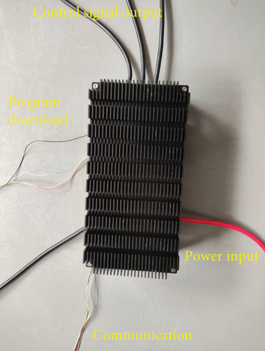
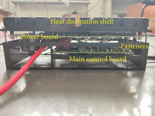
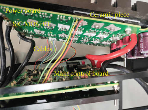
The next section primarily addresses solutions to challenges related to the drive circuit design in the speed controller, the impact of power supply on speed controller output, and issues associated with motor control influenced by high-voltage noise.
3. Methodology and Improvement
3.1. Self-Bootstrapping Voltage Reduction
In the speed controller of all-electric aircraft, the drive circuit is used to control the opening or closing of the power device, so as to convert the control signal. The drive circuit comes in two types: isolated and nonisolated. Isolated drive circuits are commonly employed in speed controllers. While an isolated drive circuit has better electrical isolation, it comes with a higher circuit cost and a more complex structure, potentially adding weight of the controller. On the contrary, nonisolated drive circuits offer advantages such as low cost, compact design, and low latency. In order to meet the lightweight requirements of all-electric aircraft, a nonisolated drive circuit is used to drive the SiC MOSFET in the three-phase inverter circuit in this paper, which is conducive to the miniaturization design of the thruster and reduces the cost of the propulsion system. The on-resistance of SiC MOSFET is determined by the voltage between the gate and source. Opting for a higher positive voltage as the drive voltage for the SiC MOSFET is generally preferred, as it reduces the on-resistance and enhances driver efficiency.
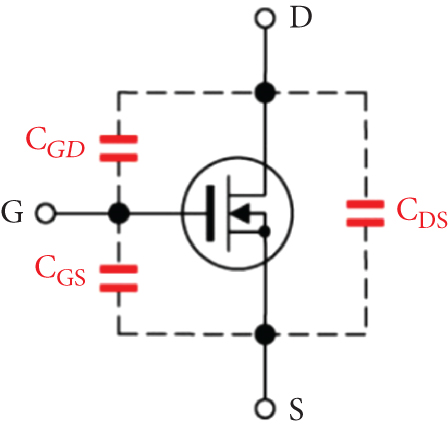
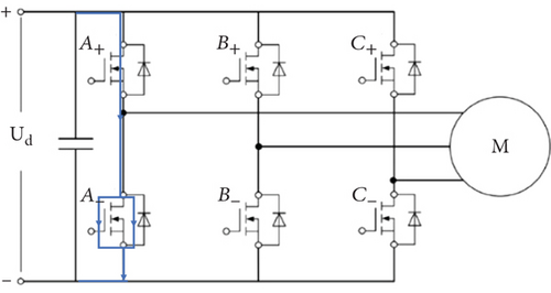
When considering turning off SiC MOSFET, the use of gate power-off increases a potential risk of instantaneous MOSFET burnout or circuit damage due to the mutual interference of the bridge arm. The interference problem of bridge arm occurs when one bridge arm mistakenly makes the other bridge arm in the same phase open during the opening process, resulting in an instant short circuit and burnout. Parasitic capacitors are present in the opening or closing process of MOSFETs, and the equivalent model is shown in Figure 3. Take phase A in the circuit as an example, as shown in Figure 4. When A+ is expected to be on and A− off, the source voltage of A+ becomes Ud immediately after A+ is on. Typically the bus voltage Ud is much larger than the driving voltage of SiC MOSFET. According to the schematic diagram of MOSFET, as shown in Figure 3, when the A− drain voltage is Ud, the parasitic capacitor in the MOSFET charges, and the voltage of the parasitic capacitor CGS increases and may surpass the driving voltage, causing the MOSFET to open. Once A− opens, then the current instantly flows through A+ and A−, causing a short circuit. In the event of an instantaneous short circuit, the MOSFET is likely to burn out. Therefore, the probability of interference under the high voltage condition is much greater than that under the low voltage condition. A similar analysis can also be carried out in the case of other bridge arms.
Therefore, aiming at the issue of serious circuit interference under high voltage in all-electric aircraft, this paper proposes a solution to turn off SiC MOSFET by using negative voltage. This approach is aimed at reducing the probability of mutual interference in the bridge arm. Considering that the gate voltage is higher than the source voltage when the MOSFET is on, and the gate voltage is lower than the source voltage when the MOSFET is off, the paper proposes to turn on the MOSFET through the self-bootstrapping voltage rise mode and turn it off through the self-bootstrapping voltage reduction mode.
Due to the symmetry of the three-phase inverter circuit, the driving mode for all phase circuit is the same. The following details the driving circuit principle, where Vh is the driving positive voltage of the MOSFET, and −Vl is the driving negative voltage of the MOSFET.
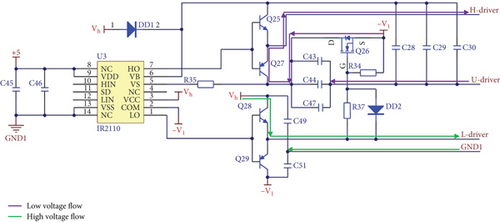
Figure 5 illustrates the working principle of the driving circuit with the upper bridge arm closed and the lower bridge arm open. When HO outputs low voltage and LO outputs high voltage, transistor Q28 is on while transistor Q29 is off. The lower bridge arm gate voltage is the same as the transistor Q28 emitter voltage, and the voltage between the lower bridge arm gate and source is Vh, corresponding to the voltage between L-driver and GND1. This configuration results in the lower bridge arm open. As the voltage between the source and drain is basically 0 V when the SiC MOSFET is on, the source voltage of the upper bridge arm is basically 0 V. Simultaneously, with the L-driver voltage at Vh, the MOSFET Q26 is on, and the voltage of the self-dropping capacitors C43, C44, and C47 is −Vl. When HO output is low, transistor Q27 is on and transistor Q25 is off. The voltage between the upper bridge gate and source is the same as that across self-dropping capacitors C43, C44, and C47. The voltage between H-driver and U-driver is −Vl, and the upper bridge arm closes. At the same time, bootstrap capacitors C28, C29, and C30 are charged to Vh. Therefore, this achieves the opening of the lower bridge arm while simultaneously closing the upper bridge arm.
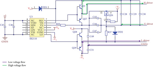
On the contrary, Figure 6 illustrates the working principle of the driving circuit with the upper bridge arm open and the lower bridge arm closed. When HO outputs high voltage and LO outputs low voltage, the transistor Q28 is off and the transistor Q29 is on. The gate voltage of the lower bridge arm is the same as the collector voltage of the transistor Q29. The voltage between the gate and source of the lower bridge arm is −Vl, equivalent to the voltage between L-driver and GND1. Consequently, the lower bridge arm closes. As the L-driver voltage is −Vl, MOSFET Q26 is off. When HO output is high, transistor Q27 is off and transistor Q25 is on. Self-dropping capacitors C43, C44, and C47 have no discharge loop, so their voltage is basically maintained at −Vl. The voltage between the upper bridge arm gate and source is the same as that across the bootstrap capacitors C28, C29, and C30, equivalent to the voltage between H-driver and U-driver. Thus, the upper bridge arm opens.
The use of self-bootstrapping voltage reduction driving mode makes the closed SiC MOSFET clamping, reducing the possibility of bridge arm interference. This adjustment is aimed at improving the operation stability and anti-interference of high-voltage distributed propulsion system circuit.
3.2. Adaptive PWM Regulation Mode for the Battery Voltage
Therefore, if the PWM duty cycle in the controller remains unchanged after the battery voltage decreases, the speed and the performance of the propeller reduce. For example, if the speed decreases to 90% of the original, the thrust also decreases to 81% of the original. It has a significant impact on the attitude adjustment of the aircraft because the thruster output does not match the expected value. So, it is necessary to increase the PWM duty ratio manually or by other means to ensure that the motor speed is unchanged. At the same time, the all-electric aircraft uses a high-voltage power supply, and the battery voltage experiences a substantial range of decrease. For example, the normal 100 V battery voltage can be reduced by 20 V, while a 10 V battery voltage can decrease by a maximum of 2 V. This wide voltage range contributes to a significant variation in motor speed when using the controller under the same input. The current controller’s limitation lies in its inability to ensure consistent output for the same input during motor operation.
3.3. Delay Compensation
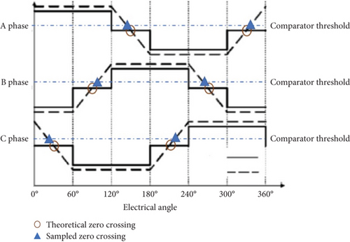
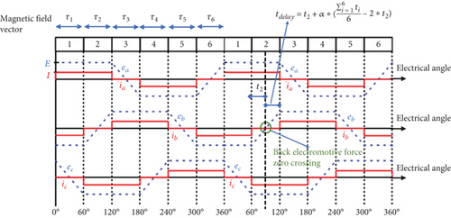
In the sensorless control of the brushless DC motor, it is often used to find the back electromotive force zero crossing and then delay the 30° electrical angle time to reverse. Accurate determination of six discrete zero crossing points is crucial for control performance. Inaccurate zero crossing detection can lead to unbalanced operation of the system, so the one-phase conduction interval is different from other phases. It results in asymmetric current waveform and high torque ripple, which reduces the efficiency of the distributed propulsion system. At present, comparators are commonly used to obtain the zero crossing of the back electromotive force. However, in high-voltage circuits, the amplification factor of circuit sampling is large, so the sampling results of the back electromotive force at low speed are easily disturbed by noise. It is necessary to set the comparator threshold to improve the reliability of the sampling results. However, this approach causes the lag of the sampled zero crossing and reduces the motor operation efficiency. The sampled zero crossing is different from the theoretical zero crossing. These differences are shown in Figure 7.
4. Results and Discussion
Considering the safety of high-voltage testing, this paper uses a DC power supply to verify the algorithm. The maximum voltage of the power supply is limited to 100 V, and all MOSFETs in the experiment are made of SiC. Disassemble the installed speed controller from the second section, still dividing it into the main control board and power board, for the purpose of testing electrical signals. This only ensures that the function is the same but the physical location is different. Use high-voltage isolation probes to collect terminal voltage signals during the operation of the motor and display them on an oscilloscope. The sampling frequency of the oscilloscope is 200 MHz. A laptop is set up to send control commands and receive data via serial communication. Protective gloves are worn during the experiment to ensure safety. The no-load experimental environment is shown in Figure 10.

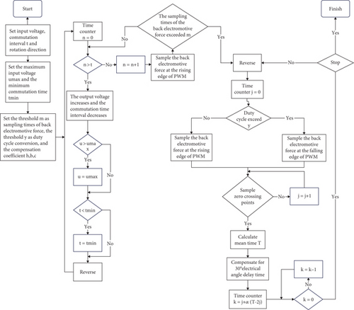
Figure 11 shows the software flowchart of the experiment process, detailing how the above design schemes are implemented. In the following experiments, only the control input is changed, while the software execution process remains unchanged. The following experiments are configured with parameter commutation interval t = 10 ms, maximum input voltage umax = 8.2 V, minimum commutation time tmin = 1 ms, sampling times m = 7, duty cycle threshold y = 50% and compensation coefficients h = 0.85, b = 7, and c = 10.
The SiC MOSFET is driven by self-bootstrapping voltage rise and self-bootstrapping voltage reduction to run the brushless DC motor. Set the voltage setting value Uset to 9.38 V and start the brushless DC motor. Then, wait for the motor to reach a steady state, and the terminal voltage during the operation of the motor is shown in Figure 12.
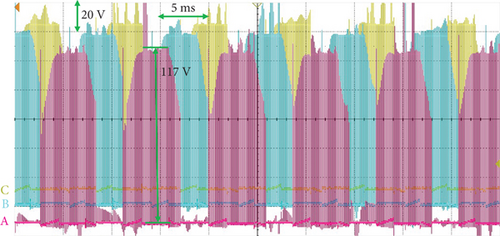
In Figure 12, the terminal voltage reaches 117 V at the bottom part of the trapezoid. At this time, the upper bridge arm opens and the lower bridge arm turns off. According to the parameters of the SiC MOSFET capacitance in Table 2, it can be calculated that the drive voltage of the lower bridge arm is around 95 V without any external devices, far exceeding the MOSFET turn-on threshold. However, in this paper, the self-bootstrapping voltage reduction drive method is applied to turn off the MOSFET, suppressing the risk of bridge arm cross-talk. Multiple experiments show that even with terminal voltage oscillations, the brushless DC motor can still run and the MOSFETs do not burn out. This outcome proves that using the self-bootstrapping voltage reduction drive method proposed in this paper to turn off the MOSFET can ensure the normal operation of the brushless DC motor and improve the anti-interference of the circuit. It is of great significance for the reliability and low cost of the high-voltage distributed electric propulsion system.
Configure the voltage setting value to 4.1 V and decrease the power supply voltage from 100 to 90 V during the operation of the brushless DC motor. Subsequently, after the brushless DC motor achieves smooth operation, the power supply voltage is further adjusted, decreasing from 90 to 80 V. The changes during the operation of the brushless DC motor are shown in Figure 13.
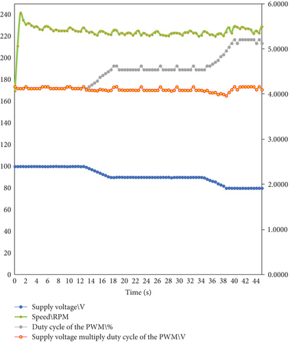
In Figure 13, the power supply voltage decreases from 100 to 90 V after 5 s and the PWM duty cycle gradually increases during the process of power supply voltage reduction. When the power supply voltage is stable, the PWM duty cycle also remains constant. When the power supply voltage drops from 90 to 80 V at the beginning of 34 s, the PWM duty cycle gradually increases again. In the whole process of power supply voltage change, the product of the PWM duty cycle and power supply voltage is basically unchanged, and the motor speed is basically constant. This observation validates that the adaptive PWM regulation mode for power supply voltage designed in this paper can make the motor adapt to the change of power supply voltage during operation. The fluctuation in power supply voltage does not impact the motor speed. When the input of the controller is the same, the output is also the same. It ensures unique output for the high-voltage distributed electric propulsion system under the same input.
Set the power supply voltage to 100 V constant and the voltage setting value to 4.1 V. Subsequently, when the motor starts and operates smoothly, the voltage setting value increases to 6.2 V. The maintenance time of the six magnetic field vectors is shown in Figure 14.
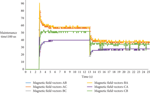
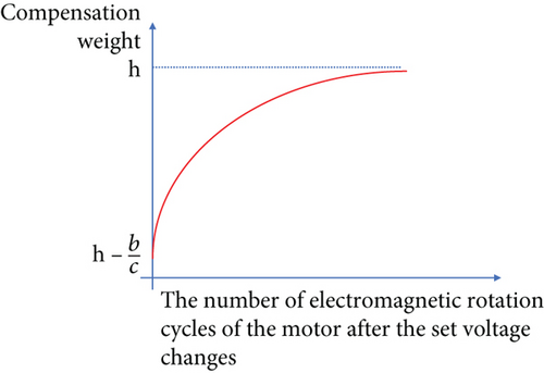
In Figure 14, within the initial 3 s after the brushless DC motor starts, the range of maintenance time of the six magnetic field vectors gradually decreases from 7 to 1.8 ms and the input power is reduced by 7 W. The maintenance time of BA and AC magnetic field vectors increases first and then decreases obviously. After the voltage setting value changes, the range of the six magnetic field vector maintenance time decreases from 1.8 to 1 ms and the input power is reduced by 9 W. The maintenance time of CA and BC decreases first and then increases obviously. The variation in compensation weight leads to the equilibrium of the magnetic field vector maintenance time. Using the delay compensation method designed in this paper results in a tendency for the maintenance time of the six magnetic field vectors to converge after the alteration of the voltage setting value.
At the same time, this paper uses different delay modes for comparison and the results are shown in Table 4.
| Delay 30° electrical angle time calculation method | Bus current (A) | Speed (RPM) | Speed per unit of power (RPM/W) |
|---|---|---|---|
| The delay compensation method of this paper | 0.19 | 220 | 11.58 |
| Half of the time between adjacent zero crossings | 0.51 | 260 | 5.10 |
| One-twelfth of the total time of the six magnetic field vectors | 0.72 | 238 | 3.31 |
| The time of zero crossing detected after reversing | 0.66 | 260 | 3.94 |
It can be observed from Table 4 that the delay compensation method proposed in this paper results in the maximum motor speed per unit power during operation. This finding further proves that this delay method exhibits the highest efficiency, contributing to improve the operating efficiency of the high-voltage distributed electric propulsion system.
Through the above experiments, it can be found that the delay compensation method proposed in this paper is helpful to reduce the influence of the comparator threshold on the zero-crossing sampling, effectively enhancing the accuracy of zero-crossing sampling.
To further validate the feasibility of the design, this paper conducted a propeller load test. The experimental setup is shown in Figure 15. The brushless DC motor and speed controller are fixed on the power propulsion test stand. The propeller is fastened to the motor using bolts to maintain the same speed between the propeller and the motor. The speed controller is placed behind the propeller so the propeller wake can pass over it for heat dissipation. The power propulsion test stand is able to measure the current, torque, and thrust generated by the propeller during motor operation. To ensure the safety of the experimenters, the laptop is placed below the power propulsion test stand. The control output is connected to the speed controller, and remote communication is used to control the laptop, which indirectly controls the motor input.
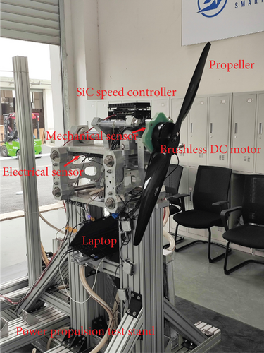
After ensuring that the equipment is connected properly, start the motor via remote communication to initiate the rotation of the propeller. Once the brushless DC motor reaches a steady state, record the data and increase its output to raise the propeller speed. The voltage setting value increases in a stepped manner from 9.38 to 46.88 V. The static data generated from this experiment are shown in Table 5.
| Uset(V) | Bus current (A) | Speed (RPM) | Input power (W) | Motor efficiency | Kilogram force (kgf) | Torque (N∙M) |
|---|---|---|---|---|---|---|
| 9.38 | 0.648 | 570 | 64.8 | 0.371 | 0.02 | 0.398 |
| 12.5 | 1.062 | 738 | 106.2 | 0.416 | 0.523 | 0.569 |
| 15.63 | 1.591 | 906 | 159.1 | 0.530 | 1.181 | 0.883 |
| 18.75 | 2.337 | 1062 | 233.7 | 0.602 | 1.933 | 1.259 |
| 21.88 | 3.321 | 1218 | 332.1 | 0.669 | 2.840 | 1.732 |
| 25.00 | 4.668 | 1398 | 466.8 | 0.697 | 3.885 | 2.208 |
| 28.13 | 6.168 | 1548 | 616.8 | 0.716 | 5.047 | 2.705 |
| 31.25 | 8.208 | 1704 | 820.8 | 0.767 | 6.559 | 3.501 |
| 34.38 | 10.351 | 1855 | 1035.1 | 0.781 | 7.843 | 4.121 |
| 37.40 | 12.607 | 1992 | 1260.7 | 0.801 | 9.144 | 4.792 |
| 40.63 | 16.269 | 2142 | 1626.9 | 0.761 | 10.665 | 5.439 |
| 43.75 | 20.716 | 2310 | 2071.6 | 0.777 | 12.719 | 6.538 |
| 46.88 | 25.135 | 2436 | 2513.5 | 0.762 | 14.558 | 7.374 |
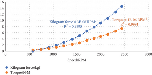
Through analysis of the data in Table 5, it is evident that the speed controller can operate at power exceeding 2.5 kW, with the maximum kilogram force produced by the propeller exceeding 14 kgf. The measured kilogram force and torque exhibit a nonlinear relationship with motor speed as shown in Figure 16. It validates the strong feasibility of the three solutions mentioned in this paper for application in high-power electric propulsion systems.
5. Conclusion
This paper emphasizes the significance of all-electric aircraft and distributed propulsion system, underscoring the importance of speed controller for electric propulsion system. Electric propulsion technology is regarded as a crucial avenue for reducing carbon emissions and environmental noise. It fosters innovation in aviation technology and propels the evolution of green aviation. In addressing challenges related to circuit interference, battery voltage fluctuations, and sampling issues which affect speed controller performance under high voltage conditions, three solutions are proposed: (a) To mitigate mutual interference of the bridge arm under high voltage, a self-bootstrapping voltage reduction driving method is proposed to switch off SiC MOSFET and improve the circuit anti-interference; (b) to address the challenge of brushless DC motor speed fluctuation caused by change in battery voltage, an adaptive PWM regulation mode for battery voltage is proposed to ensure the consistent controller output, maintaining a stable motor speed; (c) to tackle the issue of comparator threshold affecting zero-crossing detection, a 30° electrical angle delay method with delay compensation is proposed to improve the motor operation efficiency. The analysis and experimental results show that the three solutions proposed in this paper are helpful to enhance the anti-interference, stability, and efficiency of the distributed propulsion system of all-electric aircraft. The feasibility of the three solutions has been confirmed through high-power experiments. Moreover, these solutions play a crucial role in reducing the overall cost and weight of the propulsion unit.
Conflicts of Interest
The authors declare no conflicts of interest.
Funding
This research was supported by the Intelligent Aerospace System Leading Innovation Team Program of Zhejiang (Grant No. 2022R01003).
Open Research
Data Availability Statement
The data used to support the findings of this study is included within the article and is also available from the corresponding author upon request.


