Study on Impact Test System of Manipulator Based on Six Axis Force Sensor and Intelligent Controller
Abstract
With the development and application of intelligent nervous system, intelligent control system represented by machine vision has been promoted and used in various fields, including manipulator control system. Mechanical arm is the main actuator of robot and other mechanical components, but the application environment of mechanical arm is extremely complex, and with the development of industrial process, the sensitivity of technology and operating system for its arbitrary posture operation is also steadily improved. Based on the above problems, this paper designs a manipulator control system based on machine vision theory and orthogonal parallel six-dimensional force sensor to meet the working requirements of manipulator in high-precision environment. Systems hardware are consisted by machine vision structure and six dimensions of force sensor. The practical application effect of the model was verified by collision detection experiment. The relevant research can provide theoretical guidance and practical reference for the research of manipulator control field. Dance and practical application reference for the research of manipulator control field.
1. Introduction
The control of manipulator has always been an important and hot issue in mechanical control. At present, the control theory and method of manipulator have been deeply studied [1–3]. Machine vision technology takes the photosensitive element as the processing core and uses the analog signal transmitted by the optical sensor to convert and collect the electrical signal and optical signal. With the development of camera and imaging processing technology, the data information processed by machine vision processing technology can be transformed from two-dimensional to three-dimensional. Under the influence of automatic machinery production mode, industrial manipulator has become an important equipment to support modern production. How to realize the automatic control process of industrial manipulator has also become a current research hotspot.
The early vision-based manipulator control system is to process the image and obtain the target position from the image, so as to achieve the effect of intelligent control and closed-loop control [4, 5]. For example, Li y et al. used the closed-loop vision algorithm developed based on monocular and binocular vision to realize the step of pose estimation from target recognition, which is completely automatic [6–8]. However, the manipulator control system relying only on vision cannot meet the needs of modern industry because of its limited accuracy, the resulting error is also large, and the prior knowledge of the environment is required [9]. Literature [10] developed the controller of the manipulator based on the behavior data of the double rotating joint manipulator and the reinforcement learning algorithm, but there are some defects, such as limited data points and the need to configure a large amount of prior knowledge for the manipulator model, so it is impossible to control the manipulator with different structures after training one controller. The visual sensor can collect rich information in the image. By combining with the reinforcement learning algorithm, the intelligent controller can learn information from the image independently, and the control strategy is optimized by the reward and punishment mechanism to realize the manipulator control after the manipulator with different structures is trained by the intelligent controller without any prior knowledge of the manipulator structure model [10–12].
The above shows that the use of machine learning combined manipulator alone cannot meet the high-precision requirements of today’s manipulator [13]. Therefore, many scholars turn their research objectives to the six-dimensional force sensor with high-precision performance. The core technology of the development of the six-dimensional force sensor is the structural design of the sensor elastomer, and its structural form directly affects the performance of the six-dimensional force sensor [14]. With the development of robot application towards high speed and high precision, the problem of dynamic force measurement is becoming more and more prominent. The six-dimensional force sensor not only requires high sensitivity and small cross interference in each axis, but also requires a certain working bandwidth to meet the needs of dynamic force measurement. In order to adapt to different working environments, the structures of six-dimensional force sensor elastomers developed by experts and scholars are also diverse. Among them, Korean scholars have designed a six-dimensional force/torque sensor to detect the full force information of the foot of humanoid robot. The sensor is small and has adjustable and independent sensitivity to different force components [15, 16]. Ge Yu of the Institute of intelligent machinery, Chinese Academy of Sciences, and others invented an ultrathin six-dimensional force/torque sensor based on cross beam and double E-shaped film, which is used to obtain force sensing information of underwater robot wrist [17–19]. In addition, because the cross beam sensor has the advantages of symmetrical structure, high sensitivity, and small-dimensional coupling, more and more scholars improve it in order to obtain a six-dimensional force sensor with better performance [20–22]. The sensor has the characteristics of high sensitivity and small-dimensional coupling. Based on the traditional cross beam sensor, Wu C et al. [23–25] proposed a new six axis wrist force sensor by setting through holes on each sensitive beam. The sensor has good static and dynamic characteristics.
To sum up, machine vision can better meet the intelligent recognition requirements of the manipulator system, while the six-dimensional force sensor can better meet the sensitivity and accuracy requirements of the manipulator in the manipulation process. Therefore, this paper applies machine vision and six-dimensional force sensor to the manipulator control system with high accuracy requirements, in order to realize the use requirements of the manipulator control system in the environment with high intelligence and high accuracy requirements.
2. Basic Theory
2.1. Design of Controller
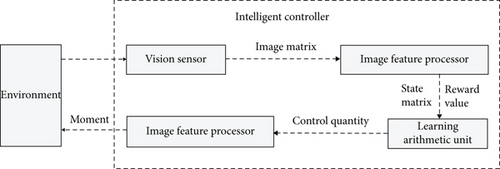
In order to realize the autonomous control of the manipulator, an intelligent controller based on machine control is designed. By learning step by step, the intelligent controller finally learns to control the movement of the manipulator, so that the end of the manipulator is controlled from the initial position to the target position. In each step, the intelligent controller collects the image of the environment through the visual sensor and obtains the next control quantity through online learning.
As shown in Figure 1, the intelligent controller includes a vision sensor, an image feature processor, a control actuator, and a learning arithmetic unit.
2.1.1. Vision Sensor
The visual sensor collects the actual information of the current environment in the form of color image, and the image matrix is the three-dimensional image matrix of RGB mode. The image matrix contains the current state and target state of the manipulator, as well as environmental information.
2.1.2. Image Feature Processor
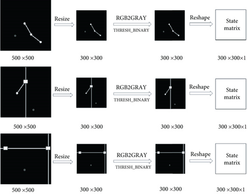
After graying and thresholding the received image matrix I, the image feature processor adjusts the size and deformation and then outputs the state matrix st to the core of the reinforcement learning algorithm. Figure 2 describes in detail the process of rr types of manipulator, xr types of manipulator, and xy types of manipulator acquiring image matrix I by visual sensor and inputting it to image feature processor for processing into state matrix st.
2.1.3. Control Actuator
2.1.4. Learning Arithmetic Unit
The learning arithmetic unit calculates the state matrix and reward value transmitted by the current image feature sensor, generates the control quantity, and inputs it into the manipulator through the control actuator, resulting in changes in the environment.
According to Equation (1), the principle in learning is that if the learning process deteriorates, the distance between the end position of the manipulator and the target position increases, and the reward value is reduced to punish. If the learning process is improved, the distance between the end position of the manipulator and the target position decreases, and the reward is carried out by increasing the reward value.
2.2. Machine Vision Learning Model
2.2.1. Camera Selection
When the industrial manipulator completes its work, it needs to obtain the visual information in the environment and locate the workpiece position or target position. Therefore, it is necessary to map the position information in the image to the real-world coordinate system, so it is necessary to calibrate the camera and establish the relationship between the coordinate systems.
When collecting information, we generally need to select an appropriate camera to collect the required information. The vision system in this paper is mainly composed of two cameras. The remote camera is fixed in front of the manipulator to shoot the target point, and the end camera is fixed at the end of the manipulator to form a hand eye system, which is used to complete the tasks of defect detection and so on. Therefore, the camera needs to have appropriate focal length, good definition, and resolution. The detailed parameters of the camera are shown in Table 1.
| Index | Camera parameters |
|---|---|
| Camera model | MindVision MV-U300 |
| Effective pixel | 2048H × 1536 V (3,000,000) |
| Pixel size | 3.2 μm × 3.2 μm |
| Signal to noise ratio | 43 dB |
| Optics | 1/2”CMOS color |
| Data interface | USB2.0 480 Mb/s |
| Transmission distance | 5 m |
| Power supply mode | USB power supply |
2.2.2. Camera Calibration
The process of camera calibration is to determine the projection matrix P converted from the world coordinate system to the image coordinate system. Camera calibration is generally divided into two parts. One is to convert from the world coordinate system to the camera coordinate system. In this step, the camera external parameters R, T (rotation matrix, translation matrix) and other parameters are determined. The second part is to convert from the camera coordinate system to the image coordinate system. In this step, the camera internal parameters K and other parameters are determined. The camera imaging model is divided into linear model and nonlinear model. The perspective projection model of the camera is shown in Figure 3 without considering the lens distortion.
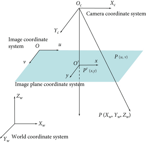
The perspective projection model contains four coordinate systems. World coordinate system Ow − XwYwZw, that is, a real coordinate system defined by the user in the real space according to the needs, reflecting the actual spatial position of the camera and the measured object. The camera coordinate system 2, its origin is the optical center of the camera, and the z-axis coincides with the camera optical axis, and the Xc axis and Yc axis are parallel to the xy axis of the imaging plane coordinate system. It is defined to describe the object position from the perspective of the camera. Like the plane coordinate system o′ − xy, this coordinate system is the plane imaged by the photosensitive element of the camera and is the coordinate system obtained by translating the camera focal length f distance along the z-axis of the camera coordinate system. Image coordinate system, that is, the coordinate system o − uv of the image we see. The origin is in the upper left corner of the image, and the unit is pixel. The optical signal collected by the camera through the sensor is converted into digital signal, that is, the image we see. An image can be regarded as a matrix of M × N, and each value in the matrix is the gray value of each pixel.
3. Six-Dimensional Force Sensor Model
In the manipulator control system, the dynamic performance of the force sensor directly affects the practical application performance of the manipulator. Force sensor is a kind of electrical component that converts force signal into relevant electrical signal. Among them, the six-dimensional force sensor can measure the force and torque information about the three coordinate axis in space at the same time. It is the most complete form of force sensor.
3.1. Orthogonal Parallel Six-Dimensional Force Sensor Model
The orthogonal parallel six-dimensional force sensor is composed of three parts: force measuring platform, fixed platform, and force measuring branch. The structure of the force measuring platform is exactly the same as that of the fixed platform. Each platform contains three support columns, which are distributed symmetrically around the z-axis of the coordinate system. There are six force measuring branches in total, which are S-type single-dimensional force sensors, and the middle part is fixed with a strain gauge for detecting the axial force on the force measuring branch. Among the six force measuring branches, three force measuring branches are placed vertically and connected with the two platforms. The three force measuring branches are placed horizontally and connected with the respective supporting columns of the two platforms. The connection methods are all elastic spherical joints, and the three vertical force measuring branches and three horizontal force measuring branches are also circumferentially symmetrical about the z-axis of the coordinate system.
Because the force measuring branch and the two platforms are connected by elastic spherical joints, ideally, the force measuring branch can be regarded as a two force element and only bear its own axial tensile pressure. Moreover, because the vertical force measuring branch and the horizontal force measuring branch are arranged orthogonally in the space, when the force received by the six-dimensional force sensor is the force in the x, y direction and the torque in the z direction, the force measuring branch mainly measured is the force measuring branch arranged horizontally. When the applied force is the moment in x, y direction and the force in z direction, the main force measuring branch is the force measuring branch arranged vertically. This arrangement of force measuring branches makes the measurement of six-dimensional external force more accurate from the structural principle, and the interdimensional coupling of six-dimensional force sensor can be reduced.
3.2. Mathematical Model of Orthogonal Parallel Six-Dimensional Force Sensor
Figure 4 is the structural diagram of orthogonal parallel six-dimensional force sensor.
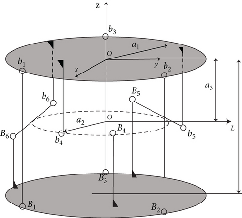
b1b2b3 represents the force measuring platform, and B1B2B3 represents the fixed platform. b1B1, B2b2, B3b3 is three force measuring branches arranged vertically, and the included angle between any two points of b1, b2, b3 and the origin o is 120°. b4B4, b5B5, b6B6 is three horizontally arranged force measuring branches, their axes are tangent to a circle with a circle center of o′, the three tangent points are the midpoint of the horizontal force measuring branch, and the included angle between any two tangent points and the origin o′ is also 120°.
The rectangular coordinate system o − xyz is the measurement reference coordinate system of the six-dimensional force sensor, and the origin o is determined as the geometric center of the lower surface of the force measuring platform, wherein, the x-axis is perpendicular to the horizontal force measuring branch b4B4, and the z-axis is perpendicular to the fixed platform B1B2B3 and upward.
3.3. Vibration Model of Orthogonal Parallel Six-Dimensional Force Sensor
Taking the whole orthogonal parallel six-dimensional force sensor as the research object, when the force measuring platform is affected by the external force Fw, its spatial motion is described by the generalized coordinate , where q1 = [qxqyqz] defines the movement of the force measuring platform about the three coordinate axis and q2 = [qmxqmyqmz] defines the rotation of the force measuring platform about the three coordinate axis.
The vibration model of the orthogonal parallel six-dimensional force sensor can be regarded as composed of six spatial single degree of freedom second-order mechanical vibration systems and one mass block M. The selection of the reference coordinate system o − xyz of the whole system is the same as that in Figure 4.
4. Design of Manipulator Control System
4.1. Design of Collision Point Detection System for Manipulator Control
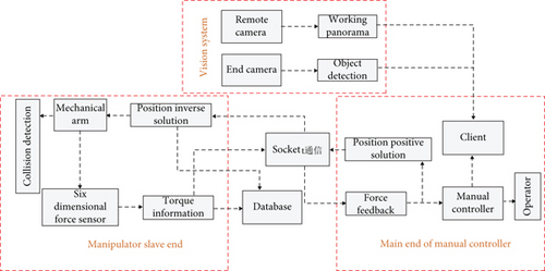
In order to test the feasibility of the application of the above six-dimensional force sensor model in the manipulator control system, this paper proposes a manipulator control system based on machine vision and six-dimensional force sensor. Different from the traditional application of six-dimensional force sensor, in order to realize the sensitivity of the manipulator control system, the collision detection method is used for the system design. The system design is shown in Figure 5.
4.2. Collision Point Detection Model
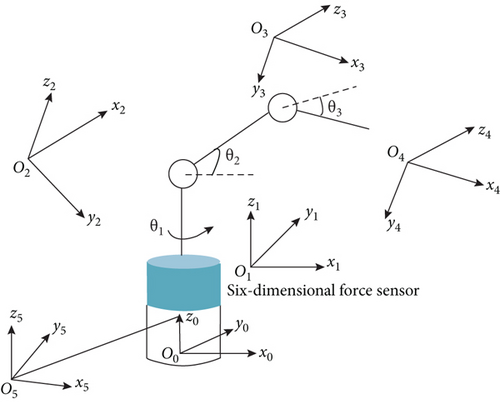
According to the different impact points and external forces, body collision can be roughly divided into single point single external force collision, single point external force/external torque mixed collision, multipoint external force collision, and multipoint external force/external torque mixed collision. The collision of multipoint and multiexternal force/external torque can be regarded as a special combination of single point and single external force. In order to achieve high-precision collision detection, the installation position diagram of the sensor in this paper is shown in Figure 6.
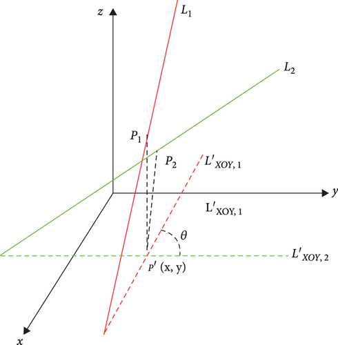
Due to the measurement error of the sensor, the calculated spatial force vector lines will not intersect at the collision point in space, but the projection in a certain plane will intersect near the projection of the formal collision point in the plane. Therefore, the intersection of the external force vector line in the plane can be obtained by the projection method, and then, the intersection coordinates can be substituted into the original equation to obtain the collision point information, as shown in Figure 7.

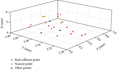
Among the preliminarily determined collision points, search the point that minimizes ; that is, it is considered to be the optimal solution closest to the real collision point. The optimal search results are shown in Figure 9.
5. Simulation Experiment
In order to verify the effectiveness and accuracy of the collision point detection model proposed in this paper, a 3-DOF manipulator model is constructed for simulation experiments, as shown in Figure 10.
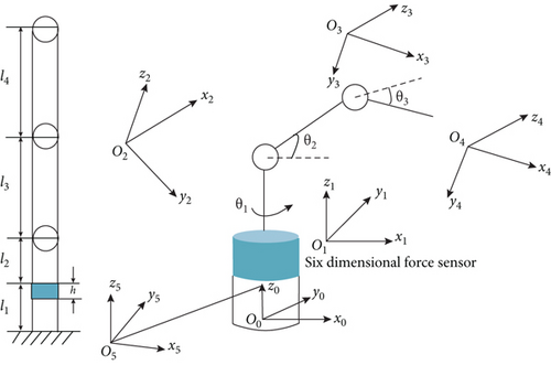
In order to reduce the amount of calculation, the connecting rod and joint center of the manipulator are symmetrical, and the center of gravity of each connecting rod is located on its own central axis.
Table 1 shows the structural parameters of each connecting rod of the 3-DOF robot in this paper. The material is alloy, ρ = 2.7 × 10³kg/m3, In Figure 10, l1 = 120mm, l2 = 150mm, l3 = 200mm, l4 = 200mm, h = 30mm. In Table 2, the member parameters are shown as follows.
| Connecting rod serial number | Quality | Relative position of centroid/mm |
|---|---|---|
| 0 | 1.598 | (0, 0, 60) |
| One | 1.686 | (0, 0.7, 0.24) |
| Two | 2.489 | (84.685, 0, 0) |
| Three | 3.201 | 104.684, 0, 0 |
The data collected by the sensor at the base changes with time. After dynamic compensation processing, the data collected by the sensor is used as the input of Equation (4) to calculate the collision point. Import the manipulator model into Adams to verify the constructed manipulator model. In the experiment, the magnitude, direction, and position of the simulated impact force are known, and the experimental result data are based on the sensor coordinate system.
In the experiment:θ1 = −π/6, θ2 = −π/6, θ2 = −π/4, , , , and . The robot moves repeatedly for 6 times according to the set parameters and carries out collision test at different points with the same collision force (100 N) when running to the third second. The experimental results are shown in Table 3.
| Serial number | Detection force/N | Component force in three directions/N | Collision position/mm | Capacity of calculation/N | Calculation position/mm | Force absolute error/N | Relative error of force/% | Position absolute error/mm | Relative position error/% |
|---|---|---|---|---|---|---|---|---|---|
| 1 | -45.01 | 116.79 | -46.36 | 122.10 | 1.35 | 0.88 | 5.31 | 4.83 | |
| 100 | -62.86 | 69.72 | -62.23 | 76.49 | 0.63 | 0.88 | 6.77 | 4.83 | |
| 63.41 | 298.71 | 64.45 | 302.47 | 1.03 | 0.88 | 3.76 | 4.83 | ||
| 62.35 | 0 | 60.38 | 1.35 | 1.97 | 2.38 | 1.35 | 1.78 | ||
| 2 | 100 | 73.95 | 38.49 | 72.75 | 37.64 | 1.20 | 2.38 | 0.85 | 1.78 |
| 25.38 | 167.03 | 24.31 | 167.90 | 1.07 | 2.38 | 0.87 | 1.78 | ||
| 72.19 | 213.41 | 70.71 | 226.90 | 1.48 | 0.58 | 13.41 | 7.78 | ||
| 3 | 100 | 30.16 | 124.08 | 29.67 | 135.71 | 0.49 | 0.58 | 11.63 | 7.78 |
| -62.28 | 486.49 | -63.28 | 503.80 | 0.99 | 0.58 | 17.31 | 7.78 | ||
| 76.9 | 64.07 | 78.76 | 261.18 | 1.81 | 0.76 | 2.65 | 2.85 | ||
| 4 | 100 | 14.69 | 36.83 | 16.42 | 261.18 | 1.73 | 0.76 | 2.16 | 2.85 |
| -62.22 | 264.19 | -61.65 | 261.18 | 0.56 | 0.76 | 3.01 | 2.85 | ||
| 92.68 | 40.03 | 94.56 | 40.46 | 2.26 | 2.20 | 0.43 | 1.55 | ||
| 5 | 100 | 10.35 | 0 | 9.67 | 0.04 | 0.67 | 2.20 | 0.04 | 1.55 |
| 36.08 | 148.03 | 37.55 | 149.93 | 1.47 | 2.20 | 1.90 | 1.55 | ||
| -82.94 | 48.63 | -84.19 | 47.32 | 1.25 | 1.95 | 0.49 | 2.39 | ||
| 6 | 100 | 48.67 | 0 | 49.61 | 2.38 | 0.93 | 1.95 | 2.38 | 2.39 |
| -27.41 | 184.16 | -29.05 | 85.84 | 1.64 | 1.95 | 1.68 | 2.39 |
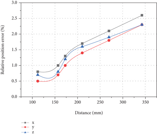
The calculation results are shown in Figures 11 and 12.
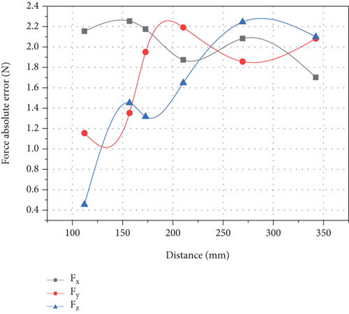
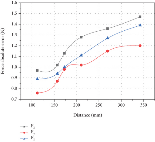
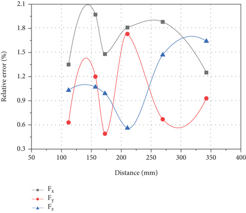
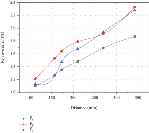
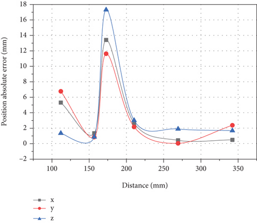
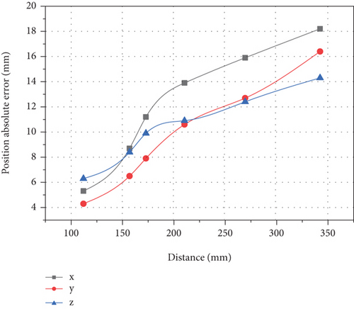
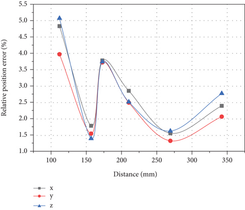
As shown in Figure 11, Figure 11(a) shows the error value of mechanical arm experimental resultant force, Figure 11(b) shows the error value of formula computer mechanical arm resultant force, Figure 11(c) shows the relative error value of mechanical arm experimental resultant force, and Figure 11(d) shows the relative error value of formula computer mechanical arm resultant force. Compared with Figures 11(a) and 11(b), it can be found that the fluctuation of mechanical arm resultant force experimental test value is significantly larger than that calculated by formula, and there is no obvious law. The difference between the maximum error value and the minimum error value is large, up to 2.26 N, and the minimum value is only 0.49 N. The change of the calculated value of the formula shows the law that it increases with the increase of the distance from the collision point, and reaches the maximum value at the farthest position from the force sensor coordinate system, which is close to 1.5 N. Comparing Figures 11(c) and 11(d), it is found that their performance rules are roughly the same as those in Figures 11(a) and 11(b). The difference is that in the relative error, the maximum values of the two are close, and the relative error of the measured value is less than the formula calculated value. Therefore, the formula calculation can reflect the relative error of the measured computer arm control system to some extent.
When the relative distance error of the mechanical arm (a) is the collision distance of the three points, as shown in the figure, the calculation error of the mechanical arm (b) is the relative distance between the collision points, and the calculation error of the mechanical arm (a) is the basic distance of the collision point, as shown in the formula of the collision point (b), and they are all within the allowable range of error. However, it changes with the distance of the collision point. The collision error first increases with the increase of the distance, and the maximum error is 16 mm, but the relative displacement error in all directions fluctuates in the range of about 5%. Compared with the formula calculation, the experimental error value is basically the same, and the farthest relative error is no more than 5%. It can be seen that this method can meet the collision accuracy requirements of the farthest point of the manipulator.
6. Conclusion
- (1)
A manipulator control system based on machine vision and six-dimensional sensor is proposed. The manipulator visual servo structure in the system can effectively capture the target and transmit it to the six-dimensional force sensor to control the motion thread of the manipulator and guide the precise operation of the manipulator
- (2)
Through the simulation experiment of impact point, it is found that the manipulator control system constructed in this paper can effectively test the impact point. At the same time, the formula calculation shows that the accuracy of the manipulator control system will not change significantly with the change of the position of the impact point. It has high accuracy and small error, and the maximum error is not more than 5%, which meets the accuracy requirements of the detection of the impact point of the manipulator
Conflicts of Interest
The authors declare that there are no conflicts of interest regarding the publication of this paper.
Acknowledgments
This research was supported by the Zhejiang Guangsha Vocational and Technical University of Construction "Mechanical Design Foundation" New Form teaching Material Construction project (No. BK0808).
Open Research
Data Availability
The experimental data used to support the findings of this study are included within the article.


