[Retracted] Green Building Design Based on 5G Network and Internet of Things System
Abstract
An information-based and intelligent comprehensive energy consumption management system should not only collect, manage, and analyze energy consumption data but also monitor the environmental data inside the building, to manage and display the real energy consumption and internal environmental quality more effectively and reliably. In order to solve this problem, the design and construction of the front-end hardware of the energy consumption management system are proposed, mainly including the design of data acquisition node and data centralization end. The design of data acquisition node includes the selection of DSP controller, wireless communication module, and data acquisition module and the design of main circuit and peripheral circuits. The design of data centralization end includes the selection of its high-performance processor and the transplantation of Linux operating system. This paper only introduces the design and research of lighting control algorithm and applies fuzzy control algorithm to intelligent lighting. The fuzzy control system is introduced, and a fuzzy controller based on intelligent lighting is created. The fuzzy control rule table and fuzzy control query table of the intelligent lighting system are obtained through the fuzzy control algorithm. According to the basic rules of light intensity control, when the indoor light intensity is greater than the set value of light intensity, the LED lamps are turned off, so when e < 0, the LED lamp is off and the PWM output value is 0. Therefore, when designing the fuzzy controller of intelligent lighting system, the basic domain of illumination intensity error E is [0500], excluding the case that the indoor illumination intensity is greater than the set value of illumination intensity.
1. Introduction
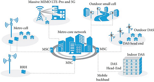
As we all know, the global environmental and resource problems have become increasingly prominent and contradictory. Countries have begun to actively seek ways to protect the environment and save energy. Due to the needs of social development and people’s life, lighting is carried out every day. The global energy consumed by lighting is huge one day. If countries can eliminate waste in lighting power consumption, then the energy consumed for power generation will be reduced, and the environmental problems caused by power generation can be effectively controlled [1]. Therefore, countries around the world began to advocate and focus on the development of intelligent lighting projects. As shown in Figure 1, people began to get involved in the field of intelligent lighting. The direct benefits brought by intelligent lighting made people realize that intelligent lighting can not only bring higher living comfort but also protect the environment and save energy, which has been widely promoted by all walks of life. Intelligent lighting has developed rapidly in the field of global lighting, and countries have opened the era of intelligent lighting. In order to meet the international development trend and according to the actual situation of China, the research and development of intelligent lighting industry can bring many benefits to China, that is, it can improve the lighting quality, provide a lighting environment beneficial to people’s life, save electric energy, and protect the environment, to truly reduce the energy consumption index and meet people’s growing needs [2]. However, according to the current research, people’s research on intelligent lighting mostly focuses on commercial lighting and office lighting, excessively pursuing people’s comfort and economic benefits in indoor lighting, ignoring that the power consumption of urban road lighting is also very huge and the lighting quality and effect of urban roads also need to be improved. With the rapid development of the Internet of things and semiconductor electronic devices, people’s demand for urban lighting is no longer limited to traditional memory, but only limited to the goal of brand lighting. With the emergence of intelligent lighting, more and more people hope that it can realize networking function (i.e., networking), intelligent function (i.e., intellectualization), and saving function (i.e., energy saving) and apply the above three functions to street lamps, meet people’s demand for urban road lighting, and realize energy conservation and environmental protection. Compared with traditional road lighting, street lamps with intelligent lighting system have obvious advantages. Computers are used as the control platform to process relevant information, and wireless communication technology is used to transmit information wirelessly; the perfect combination of the two technologies can remotely control the lighting lamps, which not only reduces the workload of managers but also can monitor, manage, and maintain the lighting situation in real time. According to the data fed back from the on-site environment, it can automatically adjust the LED lamps intelligently and provide lighting according to the actual situation of the site, to truly save electricity and protect the environment [3]. However, at present, the research of street lamp lighting in intelligent lighting is still missing or imperfect. The existing intelligent lighting street lamps are uniformly controlled on and off by the terminal, and there is a lack of design of single street lamp control. In addition, the existing street lamps are kept on for a long time during the night, and the lighting on demand is not achieved. If a street lamp breaks down, the street lamp cannot alarm the computer terminal by itself. The administrator cannot know the light and dark state of the street lamp at the first time, nor can he determine which street lamp has a problem through the computer terminal, which is not convenient for people to manage the street lamp. If the above problems can be properly solved, it will undoubtedly bring new color and impact to people’s night traffic, save more electric energy on modern urban road lighting, effectively reduce energy consumption, and improve environmental problems through power generation. Therefore, the research on LED intelligent lighting system based on Internet of things will bring more benefits to the country and people [4].
2. Literature Review
Liu and others used a BP neural network to create visual patterns of light entering a room. The inputs of the BP neural network model include the vertical illuminance of natural light, the height and azimuth of the sun, the temperature of outdoor environment, the distance between the illuminance prediction point and the window, the reflectivity of indoor wall, and the number and orientation of windows. The output is the illuminance value of the target point. Finally, the accurate control of the illuminance of the target point is realized. This method successfully solves the trouble caused by the cumbersome layout of indoor illuminance sensors in the use of natural light [5]. Tikhomirova and others took an office building in Dubai as the research object, designed an office building indoor lighting control system with building energy consumption monitoring function from the aspects of energy utilization and residents’ health, and evaluated the impact of natural light used for indoor lighting on indoor lighting and temperature energy consumption, realizing the coordinated control of natural light and artificial light source [6]. Rohimi and others investigated the light comfort of office buildings. The results show that when the natural light is completely blocked, the comfort of indoor personnel is very weak and the office efficiency is low [7]. Chen and others analyzed the research results of indoor light environment and light comfort in recent years and put forward the evaluation index of light comfort, which provides a theoretical basis for the design of buildings [8]. Hassan et al. propose an improved research algorithm to improve the energy consumption of lighting. Manage lighting control systems to reduce lighting consumption through extreme value detection. The hardware of the system is designed, and the practicability and effectiveness of the control method are verified by using the hardware platform [9]. Yousuf and others invented an intelligent lighting control system, which supports intelligent heterogeneous lighting technology. Using ZigBee technology, a wireless sensor and actuator network is constructed to collect information such as natural illumination and indoor personnel activities and change the light intensity through server control to meet visual comfort [10]. Liu and others proposed an intelligent LED lighting control system based on fuzzy logic control theory [11]. The system can be divided into two modes. In the automatic mode, the light changes with the person’s position, and the light intensity can also be controlled according to the natural light intensity. In manual mode, people can manually adjust the light intensity by using an application on a Bluetooth-enabled smartphone. In addition, the application also adds various lighting effects to users. Users can create and use different scene modes by using their mobile phone. On the premise of not affecting users’ visual comfort, they can reduce energy consumption by adjusting lights and related control systems. As China pays more and more attention to building energy conservation, national experts and scholars are also studying the rational use of natural light. Combining natural lighting with artificial lighting, the quantitative model of comfort evaluation index is established, the corresponding lighting control algorithm is studied, and a double fuzzy controller is established. The main fuzzy controller controls the opening angle with the external solar altitude angle and sky light mode as inputs to achieve rapid response. In order to improve the control accuracy, the angle fine adjustment is carried out by taking the opening angle and illumination deviation value as the input from the fuzzy controller. Under the environment of MATLAB and Dialux, based on different sky light modes and solar altitude angle, the comfort of light environment before and after light supplement as well as the energy-saving effect of only artificial lighting and natural daylighting is compared. It is proved that the proposed control method can achieve good lighting effect, and the energy-saving effect is 47% compared with the traditional method. The intelligent model of indoor illumination based on constant illumination is constructed by Leonard et al. Huang and others used the control idea of “daylight control” for the light environment of office space, combined natural light with artificial light supplement in the daytime, conducted experimental research on the energy-saving design of office lighting control system, and realized “green lighting” [12]. Durgalakshmi and others established an intelligent lighting model based on personnel displacement. The mathematical formula used in the model described the relationship between personnel position, artificial lighting equipment, and natural light and output the model using particle swarm optimization algorithm based on penalty function to find out the optimal combination of equipment dimming [13]. Chen and others established an expert system to control the indoor lighting control system combined with natural light and established an optimization model based on improved particle swarm optimization algorithm, realized the method of finding the best brightness combination of lamps in the shortest time, and achieved the lowest total energy consumption of lamps [14].
3. Method
- (1)
The hierarchical structure model is established to compare the decision-making objectives, considerations, and decision-making objects. The comparison results are expressed by relative quantitative values, as shown in Table 1, and the judgment matrix A
| Factor I versus factor j | Quantized value |
|---|---|
| Equally important | 1 |
| Slightly important | 3 |
| More important | 5 |
| Strongly important | 7 |
| Extremely important | 9 |
| Judge intermediate value | 2.4.6.8 |
- (2)
Normalize the columns of judgment matrix A
- (3)
Find the sum of the elements in each row of the judgment matrix A
- (4)
Normalize to obtain w = {w1, w2, ⋯, wi}
- (5)
Consistency of inspection results
The consistency test index is CI = λmax − n/n − 1, where λmax is the maximum characteristic root of A. Refer to the order in Table 2 to obtain the average random consistency index RI.
| Order | 1 | 2 | 3 | 4 | 5 | 6 | 7 | 8 | 9 |
|---|---|---|---|---|---|---|---|---|---|
| R | 0 | 0 | 0.6 | 0.9 | 1.1 | 1.2 | 1.3 | 1.4 | 1.5 |
Then, the consistency ratio CR = CI/RI.
- (6)
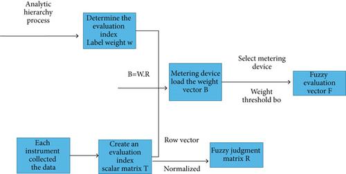
Establish judgment factor matrix t
- (7)
Calculation of comprehensive judgment matrix
- (8)
Calculate the installation weight vector of acquisition node
- (9)
Establish fuzzy judgment vector
Among them, Fi is the optimization result of the installation position weight of acquisition node i, bi is the installation position weight of acquisition node i, 0 < I < m, and bo is the weight threshold, which is taken according to the actual situation of the object. Then, bi > bo, that is, when Fi is taken as 1, the position has high weight, and the acquisition node needs to be installed; bi < bo. If 0 is taken, the metering device does not need to be installed. F in equation (9) is the fuzzy evaluation vector.
The weight of each node can be determined according to the above node distribution method [19, 20].
The data centralization end is responsible for summarizing the data collected by multiple data collection nodes and uploading it to the data management terminal. The application object of this subject is large public buildings, so the data centralization system is installed in each area. Its structural framework is shown in Figure 3.
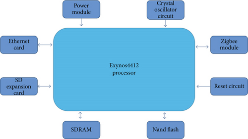
The work of the data centralization end includes receiving, sending and analyzing data information, and connecting with the data terminal by using TCP/IP and gateway. Ordinary DSP controller is difficult to realize complex functions, so the main control part of the data centralization end selects Exynos 4412 dual core processor produced by Samsung company. The processor has powerful functions. By running Linux system in the processor, a large number of complex functions can be realized. In addition to the wireless communication module, an Ethernet card is also connected to the processor port to realize the rapid reflection of various instructions transmitted by wireless communication and TCP/IP protocol and analyze and process the data packets sent by the acquisition terminal and management terminal in time. At the same time, it is also equipped with synchronous dynamic random access memory (SDRAM), NAND flash memory, and SD expansion card slot to store data, so as to improve the cache processing ability of the system for a large amount of data. Fuzzy controller includes four parts: fuzzification, fuzzy reasoning, knowledge base, and clarity. The schematic diagram of fuzzy controller is shown in Figure 4.

The work of the data centralization end includes the reception, transmission and analysis of data information, and the connection with the data terminal by using TCP/IP and gateway. It is difficult for the ordinary DSP controller to realize complex functions, so the main control part of the data centralization end selects the Exynos 4412 dual core processor produced by Samsung. The processor has powerful functions. By running Linux system in the processor, a large number of complex functions can be realized. In addition to the wireless communication module, an Ethernet card is also connected to the processor port to realize the rapid reflection of various instructions transmitted by wireless communication and TCP/IP protocol and analyze and process the data packets sent by the acquisition terminal and management terminal in time. At the same time, it is also equipped with synchronous dynamic random access memory (SDRAM), NAND flash memory, and SD expansion card slot to store data, so as to improve the cache processing ability of the system for a large amount of data [21, 22].
Fuzzy control has the following basic operations.
3.1. Fuzzification Operation
where xo is the clarity of the input, x is the fuzzy set, and Fz is the fuzzier.
3.2. Sentence Connection Operation
where Ri, i = 1, 2, 3, ⋯, n; numbers represent the fuzzy implication represented by this provision; also represents the combinatorial operation of all relationships.
3.3. Synthesis Operation
where x and y represent the input fuzzy quantity, z represents the output fuzzy quantity, and represents the sentence connection operator, and “o” represents the composition element operator.
3.4. Clarity Calculation
where zo represents the clarity amount and Df is the clarity operator.
At present, the common network software platform architecture is generally divided into C/S and B/S. The previous building energy consumption management platform usually adopts the form of traditional C/S architecture, that is, client/server architecture. Its feature is that users connect to special servers through client software, and all operations are completed based on the client. Therefore, the operation of C/S architecture needs to establish a special local server to complete various connections and information interaction, which is less flexible. At the same time, the client software is developed for special projects and servers, which is difficult to upgrade and maintain and has low universality. The B/S architecture, namely, browser/server, is an improvement based on the C/S architecture. In order to solve the problem of poor universality and flexibility of the original C/S architecture, the application of Internet and web side technology is added. Through the application of dynamic web page technology and cloud server technology, the B/S architecture can realize cross space and cross platform development and use. Users only need to visit the web page through the browser anytime and anywhere to realize the functions that need complex client software in C/S architecture, which greatly reduces the development cost and operation and maintenance cost of the platform.
The infrastructure of B/S architecture is divided into presentation layer, application layer, and data layer, as shown in Figure 5 [23, 24].

When using this mode, the operations of various functions are mainly concentrated on the web page, and the data interaction is realized through the connection between the web server and the database with the help of the browser software on the personal computer and mobile phone. Users can use a variety of browsers, such as Internet Explorer, Google Chrome browser, and 360 browser to access the web interface. Only the commonly used browser can solve the functions that can be realized by the specific and professional application client required in the original traditional mode.
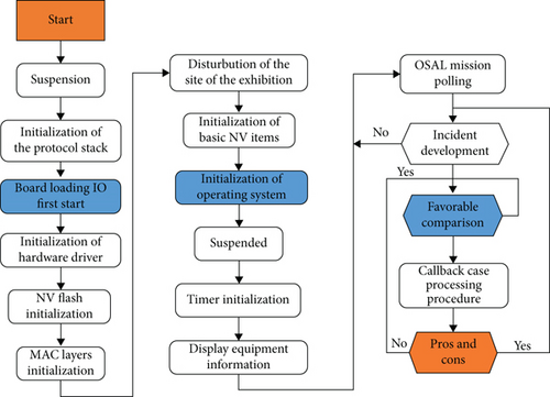
There are many contents of ZigBee protocol. CC2530 chip has provided ZigBee physical layer and MAC layer functions. ZigBee development is mainly for various specific applications. The upper layer protocol needs to use a mature ZigBee protocol stack, which is implemented by code. All devices in the same network must conform to a protocol stack specification. Z-stack is a protocol stack launched by TI company and ZigBee alliance. It is suitable for TI’s CC2530 series chips. CC2530 chip is used in the hardware design of intelligent lighting system, so Z-stack protocol stack is used for development. Z-stack is constructed with the idea of the operating system and adopts the event round robin mechanism. After the initialization of each layer is completed, the system enters the low-power mode. When an event occurs, the system is awakened and enters the interrupt processing event. After the event is completed, it reenters the low-power mode. If several events occur at the same time, the system will judge the priority and process them one by one. This system can greatly reduce the power consumption of the system. The workflow of Z-stack mainly includes system startup, driver initialization, osal initialization and startup, and task polling of the operating system. The structure of Z-stack protocol stack is shown in Figure 6.
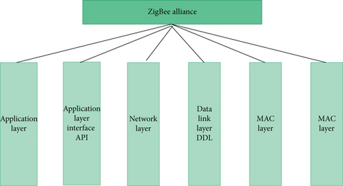
According to IEEE 802.15.4 and ZigBee standards, the Z-stack protocol stack implements API application function interface layer, Hal hardware abstraction layer, MAC media access layer, NWK network layer, osal operating system abstraction layer, security layer, and ZDO device object layer [25].
In the protocol stack, the application layer has covered the APS sublayer and ZDO connected with the network layer. The network layer ensures the correct operation of the MAC layer and provides a suitable interface to connect the application layer, including two service entries: data service entry and management entry. The former realizes network level protocol data unit and protocol specific routing. The latter can configure a new device, start a network, join or leave the network, address allocation, etc. The security specification involves the security methods provided by ZigBee, including key establishment, key transmission, framework protection, and device management. The media access control layer follows the IEEE 802.15.4 protocol and is responsible for the establishment, maintenance, and termination of wireless data links between devices, data transmission and reception in confirmation mode, optional time slots, low delay transmission, and supports various network topologies. Each device in the network is addressed with a 16-bit address. The semiopen source code, media access layer, network layer, and application support layer of Z-stack protocol stack have not been modified, but the developers of Z-stack provide a fully functional API function set to modify and write to meet the needs of practical applications. The general steps for Z-stack protocol stack to realize wireless data communication are networking, calling the networking function of the protocol stack, and adding the network function to realize the establishment of the network and the addition of nodes. Sending: the sending node calls the wireless data sending function of the protocol stack to realize wireless data sending. Receiving: the receiving node calls the wireless data receiving function of the protocol stack to realize wireless data receiving. The main workflow chart of Z-stack is shown in Figure 7.
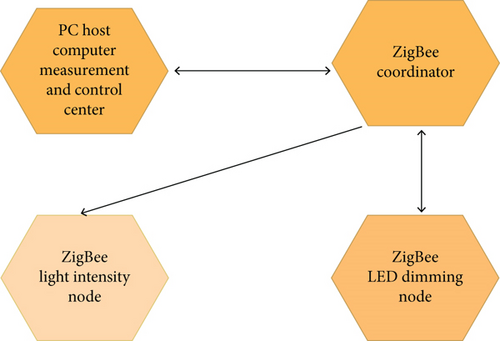
The intelligent lighting system is composed of PC host computer measurement and control center and wireless sensor control network. The PC host computer measurement and control center is the host computer human-computer interaction interface made by LabVIEW, and the wireless sensor control network is composed of ZigBee network. ZigBee network includes ZigBee coordinator, ZigBee LED dimming node, and ZigBee illumination intensity node. PC upper computer measurement and control center communicates with ZigBee coordinator through serial port; ZigBee coordinator communicates with light intensity node and dimming node through ZigBee wireless network; ZigBee LED dimming node is equipped with LED lamps, and the light intensity node is equipped with light intensity sensor. The overall framework of intelligent lighting system based on ZigBee technology is shown in Figure 8.
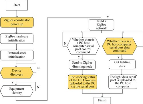
The main tasks of ZigBee coordinator in ZigBee wireless network include device discovery, device identification, and network establishment. ZigBee coordinator communicates with PC upper computer measurement and control center through serial port, obtains the control command sent by it, and uploads the light intensity detection data. Figure 9 is the workflow chart of ZigBee coordinator.
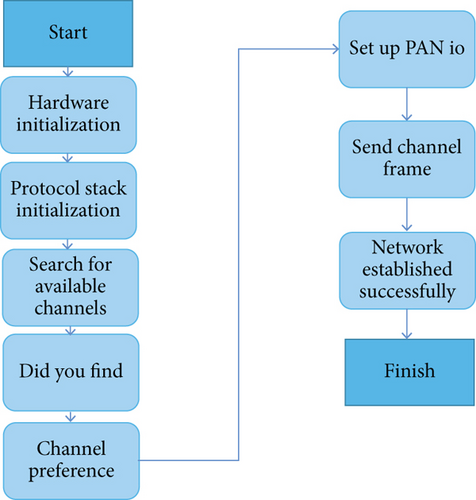
- (A)
The application layer sends NLME networkformationrequest to the network layer
- (B)
After receiving the request, the network layer sends the MAC_MlmeScanReq request to the MAC layer
- (C)
MAC layer starts channel energy detection and feeds back the MAC_MLME_SCAN_CNF detection results to the network layer
- (D)
The network layer selects the best channel group according to the result returned by the MAC_MLME_SCAN_CNF and sends a request to the MAC layer using the MAC_MlmeScanReq primitive
- (E)
MAC layer scans the channel and reports the scanning information to the network layer
- (F)
The network layer selects the channel and pan identifier according to the scanning results and then sets the 16-bit short address 0x0000 of the coordinator in the network
- (G)
The network layer sends the MAC_MlmeStartReq request primitive to the MAC layer. If the status information returned by the MAC layer function MAC_MLME_STAR_CNF is success, the network is established successfully
The coordinator establishes ZigBee network through the above seven steps. After completing network establishment and channel selection, the coordinator is equivalent to a routing device in the network. The network establishment process is shown in Figure 10.
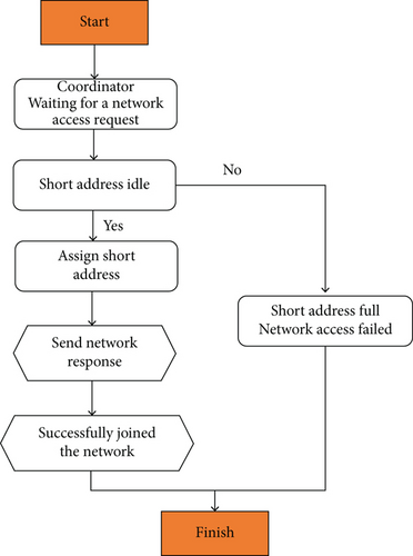
If each equipment wants to join the network established by the coordinator, it must join the network access process through a certain application. After the establishment of the network coordinator, the coordinator passively waits for the network device to apply to join the network. As long as the received MAC layer sends the MAC mlmessociatereq request primitive, it indicates that there is a node device applying to enter the network through the MAC layer, as shown in Figure 11, mainly through the following eight steps.
LabVIEW programming environment is the same as other visual development environments. The program interface and code are separated. The program interface is called VI front panel, and the code is called VI program block diagram. The front panel is a graphical user interface with interactive input and output VI controls, which are called input control and display control, respectively. Input controls, including switches, buttons, and other types of input devices, can input the input control data and provide it to the program block diagram. The display control includes graphics (graph and chart), LED, and other display output objects. The data processed by the program block diagram is displayed through the display control. The front panel inputs and outputs data, and the data processing is realized by program code programming. The program programming in LabVIEW is built in the form of block diagram. The program block diagram is the graphical source code to realize the logic function of VI system. The programming elements in the block diagram include not only the connection terminals corresponding to the controls on the front panel. There are also functions, sub-VI, constants, structures, and connections. The node types and functions of the program block diagram are shown in Table 3.
| Node type | Function |
|---|---|
| Function | The elements of a function in execution are equivalent to operators and functions |
| Sub-VI | Take the whole VI program Z as a part of another VI program, which is equivalent to a subroutine |
| Express | Sub-VI assisting in measurement tasks |
| Structure | Execute control elements, such as for loop, while loop, and conditional structure |
Each object is wired to create a program block diagram. Connection connects the input control with the display control and function or sub control, from the data of the input control to the stream function and sub-VI, then from these functions and VI to other functions and sub-VI, and finally to the display control. The intelligent lighting system of green building is mainly composed of ZigBee wireless sensor control network and PC host computer measurement and control center. The ZigBee coordinator in the wireless sensor control network is connected with the PC host computer measurement and control center through 230 to USB serial port. The communication connection between the two completely depends on serial communication, so the host computer needs to configure the driver and related programs of serial communication, that is to say, serial communication is the most critical step to be realized by LabVIEW. Ni company provides users with a variety of hardware devices in LabVIEW to meet different measurement and control requirements, including data acquisition hardware (DAQ), real-time measurement and control, GPIB, serial port and instrument control, and sound and vibration measurement and analysis; through rich drivers, LabVIEW can easily connect and communicate with any hardware device provided by Ni. Through general drivers or interfaces, such as visa, IVI, OPC, and ActiveX DLL, LabVIEW can communicate with almost any manufacturer or even self-made hardware. The connection between the upper computer of the intelligent lighting system and the wireless sensor control network can be realized by calling the visa serial port function through LabVIEW.
The above eight VI can be configured with serial communication function, and the specific functions are shown in Table 4.
| VI name | Function |
|---|---|
| Visa configuration serial port | Serial port initialization configuration |
| VISA write | Writes data from the buffer to the specified serial port |
| VISA read | Read the byte length of the specified length from the serial port to the buffer |
| Number of bytes of visa serial port | Returns the number of input buffer bytes of the specified serial port |
| Visa serial port interrupt | Send interrupt operation to the specified serial port |
| Visa set I/0 buffer size | Sets the size of the serial port IO buffer |
| Visa off | Close the serial port |
| Visa empties the I/O buffer | Clear serial port I/O buffer |
Intelligent lighting system PC: the main functions of host computer measurement and control center are as follows: analyze the light intensity data uploaded by ZigBee coordinator through serial port; display the light intensity data after analysis; display the historical data drawing of light intensity data; save the historical data of light intensity; after analyzing the light intensity data, the brightness PWM value of the lamp is transmitted to the ZigBee coordinator through the serial port; users can turn on and off the lights manually; users can send instructions directly to ZigBee coordinator through serial port.
On the basis of hardware circuit design and system function design of intelligent lighting system, the overall scheme of intelligent lighting system and the overall framework of intelligent lighting system are designed. This paper introduces the software development environment of wireless sensor control network and PC host computer measurement and control center, designs the program of ZigBee coordinator, ZigBee light intensity node, and ZigBee LED dimming node of wireless sensor control network, and designs the LabVIEW program of green building intelligent lighting system of PC host computer measurement and control center.
4. Experiment and Discussion
The fuzzy controller includes four parts: fuzzification, fuzzy reasoning, knowledge base, and clarity. The schematic diagram of the fuzzy controller is shown in Figure 12.
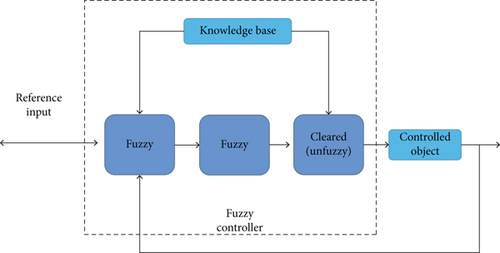
Among them, the “and” operation usually uses the method of taking the small or quadrature, and the “O” synthesis operation usually uses the method of maximum, minimum, or maximum product. Clarity is to solve the fuzzy. The output fuzzy quantity is obtained through fuzzy reasoning. For the actual control computer, only the accurate quantity can be recognized. Defuzzification is to accurately solve the output fuzzy quantity. The fuzzy quantity is transformed into the required accurate quantity. There are usually methods such as maximum center of gravity method and maximum center of gravity method.
The three letters belong to language variables, but x and y are conditional input variables, and Z belongs to control variation. Ai, Bi, and Ci ( = l, 2, ⋯), they are the amount of language change in their respective domains, and all these principles together form a rule database.
- (1)
Fuzzification operation
- (2)
Sentence connection operation
- (3)
Synthetic operation
- (4)
Clarity operation
where zo represents the clarity amount and DF is the clarity operator.
The knowledge base of fuzzy controller consists of two parts. One part is the database used, and the other part is the collection of all fuzzy control rule bases. The database contains some parameter data related to data analysis, such as numerical conversion and spatial segmentation rules. Fuzzy control rules are the experience of system operators in years of hard work.
4.1. Input Conversion
For the processing of actual input variables, it is necessary to convert them to the required range in a linear or nonlinear way.
The universe is either continuous or discrete. Generally speaking, quantization can be uniform or nonuniform. Tables 5 and 6 show the case of uniform quantization and the case of nonuniformity, respectively.
| Quantization level | -5 | -4 | -3 | -2 | -1 | 0 | 1 | 2 | 3 | 4 | 5 |
| Variation range | (-5.5, -4.5) | (-4.5, -3.5) | (-3.5, -2.5) | (-2.5, -1.5) | (-1.5, -0.5) | (-0.5, -0.5) | (0.5, 1.5) | (1.5, 2.5) | (2.5, 3.5) | (3.5, 4.5) | (4.5, 5.5) |
| Quantization level | -5 | -4 | -3 | -2 | -1 | 0 | 1 | 2 | 3 | 4 | 5 |
| Variation range | (-3.2, -1.60) | (-1.6, -0.8) | (-0.8, -0.4) | (-0.4, -0.2) | (-0.2, -0.1) | (-0.1, 0.1) | (0.1, 0.2) | (0.2, 0.4) | (0.4, 0.8) | (0.8, 1.6) | (1.6, 3.2) |
4.2. Fuzzy Segmentation of Input and Output Space
Various hypothetical languages in the relevant provisions of fuzzy control form the fuzzy input space, and the language representing the corresponding solutions forms the fuzzy output space. The variable values of various hypothetical situations all belong to the fuzzy language pseudonym Lu, and all these language names together constitute the fuzzy set of various hypothetical languages. Each fuzzy language name will be associated with a fuzzy set, and how fine its fuzzy control can depend entirely on its order of magnitude. If negative Bi stands for negative large, it is called NB for short; negative medium stands for negative medium, referred to as NM for short; negative small stands for negative small, abbreviated as NS; zero stands for zero, abbreviated as ZE; positive small stands for positive small, abbreviated as PS; positive medium stands for center, referred to as PM for short; positive big stands for Zhengda, abbreviated as Pb. The number of fuzzy segmentation also gives the number of fuzzy rules in the optimal case. For example, for a two input single output fuzzy system, the fuzzy segmentation number is 3 and 7, and then, the rule of the optimal number of products is 21. Therefore, the more the number of fuzzy segmentation, the more the number of controllable criteria; the fuzzy segmentation cannot be too large; otherwise, more controllable rules are needed, which also makes things complicated. Similarly, if the number of fuzzy segmentation is small, the rules will be too general and it is difficult to adjust the relevant situations. Nowadays, there is still a lack of a guiding way and process that can give a good number of fuzzy segmentation, which still needs to seek experience and try.
According to the theory of fuzzy control and the composition principle of fuzzy controller, the intelligent lighting system adopts the error e = Ed − Ei and error change Se between indoor light intensity Ei and illuminance set value Ed as the input variables of fuzzy controller, and the output is the system control value PWM to form a two-dimensional fuzzy controller. In building characters, the standard of light intensity is generally more than 150 lx. It will not exceed 750 lx. According to the illuminance requirements of building lighting, the universe of light intensity is [0, 1000 lx], the set value of light intensity of building lighting is ed = 500 lx, the basic universe of light intensity error E is [−500,500], the basic universe of error change Oe is [−100100], and the basic universe of system control value PWM output is [0,100%]. According to the basic rules of light intensity control, when the indoor light intensity is greater than the set value of light intensity, the LED lamp is turned off. Therefore, when e < 0, the LED lamp is turned off and the PWM output value is 0. Therefore, when designing the fuzzy controller of intelligent lighting system, the basic domain of illumination intensity error E is [0500], excluding the case that the indoor illumination intensity is greater than the set value of illumination intensity, which verifies the effectiveness of the experiment.
5. Conclusion
Aiming at the problem of energy consumption in buildings, in response to the key energy-saving project “green lighting” of the 12th Five-Year Plan, a green building intelligent lighting system based on the Internet of things is designed. The specific work is mainly divided into four stages: intelligent lighting system design, system hardware design, system software design, and system fuzzy control algorithm design. Firstly, the task function of the intelligent lighting system of green building is analyzed as a whole. The main tasks of the intelligent lighting system are detecting the light intensity of indoor specified position, intelligent dimming of indoor specified position light source, uploading the indoor light intensity data, and light source working state data. The wireless sensor network and intelligent lighting control system are selected and analyzed, and then, the basic lighting sensor network and intelligent lighting control system are selected from the PC. After determining the functional requirements of the intelligent lighting system, the hardware circuit of the intelligent lighting system is designed. From ZigBee selection and light intensity sensor selection in wireless sensor control network to ZigBee wireless communication module circuit design, light intensity sensor circuit design and LED lamp driving circuit design. Finally, cc2530f256 of Company II is selected as the ZigBee chip of wireless sensor control network, and bh1750fvi digital light intensity sensor is selected as the sensor of system light intensity acquisition node. Based on the hardware circuit design and system function design of intelligent lighting system, the overall software scheme of intelligent lighting system is designed. The overall framework of intelligent lighting system is designed. This chapter introduces the software development environment of wireless sensor control network and PC upper computer measurement and control center, designs the program of ZigBee coordinator, ZigBee light intensity node, and ZigBee LED dimming node of wireless sensor control network, and designs the LabVIEW program of green building intelligent lighting system of PC upper computer measurement and control center. Finally, the design and research of intelligent lighting system control algorithm are introduced, and the fuzzy control algorithm is applied to intelligent lighting system. In this paper, the fuzzy control system is introduced, and the fuzzy controller of the intelligent lighting system is designed. The fuzzy control rule table and fuzzy control query table of the intelligent lighting system are obtained through the fuzzy control algorithm. The best adjustment value of the intelligent dimming can be obtained through the fuzzy control query table. The intelligent dimming control of intelligent lighting system can be realized by command. For the work done in this paper, the following aspects can be further studied in the future: for different types of building structures and facility types, further study the node layout strategy for energy consumption data collection and expand the collected data types so that the system can be universal in various types of buildings.
Conflicts of Interest
The authors declare no competing interests.
Acknowledgments
This work is supported by the source of the project: the Social Science Development Research Project of Hebei Federation of Social Sciences in 2019 “Research on the Activated Design Model of Postindustrial Landscape in Hebei Province” (Number 2019031301001).
Open Research
Data Availability
The labeled dataset used to support the findings of this study are available from the corresponding author upon request.


