[Retracted] Adjustment Method of “FAST” Active Reflector Based on Optimal Fitting Strategy
Abstract
The adjustment method of the fast active reflector of “Chinese heavenly eye” is studied. Firstly, this paper studies the offset characteristics of fast main cable node position, combined with the position of the celestial body to be measured, the follow-up coordinate system is established, and the optimal fitting model of active reflector adjustment based on discrete main cable node is established by using the idea of optimal fitting of the ideal surface. Secondly, the genetic algorithm is used to solve the minimum root mean square error (RMSE). The offset of the triangular reflector is driven by the offset of the main cable node, so that the working area is closer to the ideal paraboloid, and the maximum electromagnetic wave signal receiving ratio is achieved. Finally, rotate the coordinate data of each main cable node according to the known celestial body angle and use the Lagrange operator method to obtain the shortest distance from the actual offset point to the ideal paraboloid as the objective function, with the radial expansion range of the actuator and the variation range of the distance between adjacent points as constraints, and the size of the electromagnetic wave contact area is the basis for judging the amount of information, and a reflector adjustment model for the optimal displacement strategy of discrete main cable nodes is established. Through the test, concluded that the optimal fitting strategy is ideal, the model can accurately obtain the fast active reflector adjustment method under the constraint conditions. Through the test, the conclusion that the optimal fitting strategy is ideal is obtained, and the fast active reflector adjustment method that the model can accurately obtain under the constraints is verified.
1. Introduction
In the early 1990s, since the existing radio telescopes in the world can no longer meet the needs of existing scientific and technological development, the international astronomical community proposed the construction of large-scale radio telescopes to promote further human exploration of the universe (Wu, 1995) [1]. The five-hundred-meter Aperture Spherical radio Telescope (FAST) is a major scientific and technological innovation achievement with independent intellectual property rights in China. As one of the countries with the earliest start and fastest development of celestial literature in the world, many scientists have focused on many cutting-edge and hot topics of astrophysics and creatively proposed to independently develop a new type of large aperture antenna, namely, China’s celestial eye (hereinafter referred to as “fast”), which is a major scientific and technological innovation achievement with independent intellectual property rights in China [2]. The “FAST” telescope is a 500 m-aperture spherical reflector radio telescope with extremely high sensitivity in the world, covering a wide range of astronomical contents, and is engaged in the initial turbidity of the universe, dark matter, dark energy and large-scale structure, the evolution of galaxies and the Milky Way, stellar objects, and even observational research on solar system planets and adjacent space events (Nan and Jiang, 2017) [3]. The “FAST” telescope mainly observes celestial objects through the adjustment of its active reflector, and the active reflector adjustment technology is an important technical means to improve the observation accuracy of radio telescopes (Wang et al., 2022) [4]. Therefore, the active surface adjustment method used in this study drives the offset of the triangular reflection panel and the offset of the main cable node, so that the working area is closer to the ideal paraboloid, so as to achieve the maximum electromagnetic wave signal reception ratio and ensure the safe and efficient operation of the fast telescope, which is of great significance to improve the level of scientific research in China, and also provides a good reference for the research in the same field of the international community.
At present, there are many studies on the “FAST” active reflector [5–8]. As early as 2006, some scholars theoretically and empirically studied the motion of the paraboloid of each unit spherical block during the telescope tracking process [9]. After that, some scholars have analyzed the surface shape accuracy of FAST based on the structure and working principle of FAST active reflector and on the basis of reflector unit dynamics. Also, the fitting accuracy of FAST instantaneous paraboloid was studied [10–12]. Wu and Zhang (2008) fit a paraboloid based on the least squares method and calculated the fitting accuracy of the paraboloid in the FAST reflection surface and found that the surface accuracy is the highest when the paraboloid vertex is at the center of the circle [13]. There are also some scholars who have verified, analyzed, and optimized the FAST project’s active reflector measurement control scheme on the scaled-down radio astronomical telescope model [14–17]. Luo et al. (2011) proposed an integrated astronomical trajectory planning model and carried out the corresponding derivation and analysis to obtain the relationship between the observation trajectory of FAST and the corresponding coordinate of the center point of the cable-net paraboloid with time [18]. Li and Zhu (2012) analyzed the pros and cons of the parabolic deformation strategy based on the premise of the minimum difference between the parabolic arc length and the spherical arc length during the deformation process of the reflecting surface and through the smooth transition between the parabolic edge and the spherical surface [19]. Wang et al. (2022) used the azimuth and elevation angles to determine the positional relationship between the observed object, the origin, the curved surface where the feed cabin is located, and the reference sphere, and based on the limitation of the adjustment range of the reflective panel, the particle swarm algorithm was used to determine the equation of the paraboloid [20]. Based on the research on the “FAST” active reflector, some scholars have established a model to adjust the paraboloid to determine the receiving ratio of the feed cabin to improve the observation accuracy of radio telescopes [21–24]. Li et al. (2020) combined with the joint simulation of kinematics and control, hardware in the loop simulation test and other methods, realized the accurate positioning of the feed source in the feed cabin in the 100 m large-scale space and overcome the effects of high-altitude wind disturbance, steel cable vibration, and its own motion coupling [25]. Li et al. (2022) combined Fermat’s principle to simulate the electromagnetic wave reflection in three-dimensional space, calculate the receiving ratio of the feed cabin, and test the data results, indicating that FAST can freely adjust the autonomous surface in a certain radio frequency band and obtain a higher acceptance ratio [26].
To sum up, the existing extensive research on the “FAST” active reflector, the fitting accuracy of fast instantaneous paraboloid, adjusting paraboloid to determine the receiving ratio of feed cabin, and other aspects has laid a solid theoretical and practical foundation for this paper. However, the existing research also needs to be further deepened, such as the distance between the actual offset point of the main cable node and the ideal paraboloid can still be further reduced, and the electromagnetic wave receiving ratio of the paraboloid reflector still needs to be further improved [27]. By studying the offset characteristics of FAST’s main cable node position, establishing the follow-up coordinate system combined with the position of the celestial body to be measured, and adopting the idea of optimal fitting of the main cable node to the ideal surface, this paper establishes the optimal fitting model of active reflector adjustment based on discrete main cable nodes [28, 29]. On this basis, the genetic algorithm is used to solve the minimum root mean square error, and the offset of the main cable node is used to drive the offset of the triangular reflector. Thus, the working area is better close to the ideal paraboloid to achieve the maximum electromagnetic wave signal reception ratio.
In the following innovation of this paper, the following coordinate system is introduced, which effectively simplifies the geometric operation process, reduces the calculation and model complexity, and adopts the idea of overall deviation distribution, which can make the main cable nodes approach the ideal paraboloid more accurately. At the same time, the optimization model is established by using the known constraints and solved by the genetic algorithm. In the process of solving, the global control variables are added to screen out the bad values.
The global optimal solution of the offset of each main cable node in the working area is obtained by a genetic algorithm, and the final optimal solution is h = 300.8169, f = 140.6192. The paraboloid trajectory equation (1) of the actual offset in the follow-up coordinate system and the coordinates of the main cable node after the offset are obtained. The coordinates of the main cable node after the offset in the reference coordinate system are obtained through the inverse transformation of the rotation matrix. The mean value of the distance change between adjacent nodes is 0.0633%, and the average length of the radial shrinkage of the main cable node is 0.20343.
2. Basic Assumptions and Index Selection
2.1. Basic Assumptions
In order to facilitate the study of the problem, the following hypotheses are put forward: (i) electromagnetic wave signal and reflected signal are regarded as linear propagation. (ii) The reflecting panel is smooth, and the electromagnetic beam is completely reflected after passing through the reflecting surface. (iii) The electromagnetic beam from the measured celestial body is parallel incidence. (iv) All components of the active reflecting surface are rigid bodies. (v) All data sources involved in this study are true, accurate and scientific.
2.2. Symbol Description
In combination with modeling theory and method, there are 6 variables involved, as shown in Table 1.
| Serial number | Symbol | Description |
|---|---|---|
| 1 | R | Reference spherical radius |
| 2 | f | Focal length of ideal paraboloid |
| 3 | h | Vertex offset |
| 4 | d | Deviation value of main cable node |
| 5 | D | Overall deviation distribution vector of working area |
| 6 | q | The unit vector outward along the normal direction of the sphere at the main cable node |
3. Trajectory Equation of Ideal Paraboloid under Nonworking State of Active Reflector of Radio Telescope Based on Ergodic Algorithm
3.1. Research Approach
According to the measurement requirements of the radio telescope, the focus of the ideal paraboloid is in the feed cabin; that is, the coordinates are (0, 0, -0.534R). When the object is directly above the reference sphere, the main cable node of the ideal paraboloid vertex is the easiest to study the offset direction of all nodes; so, the paraboloid trajectory equation can be transformed into a function related to the radial expansion distance h of the vertex. For the convenience of calculation, the following coordinate system with the direction of the observed celestial body as the reference is introduced, and the unit vector outward along the spherical normal direction at the main cable node is introduced to study the radial displacement deviation d. The component of the deviation in the coordinate system forms a functional relationship with the original coordinates of the main cable node, and the objective function only related to the radial expansion distance h can be obtained by substituting the assumed ideal paraboloid equation. The method of RMSE of overall deviation distribution is used to find the most ideal radial displacement of all displaced main cable nodes in the working area. Combined with the constraints of radial shrinkage range, the optimization model of the ideal paraboloid trajectory equation is established. Using the traversal algorithm to calculate the deviation of each node, the h of the optimal solution can be found, and the trajectory equation can be solved [30].
3.2. Displacement Model of Active Reflector
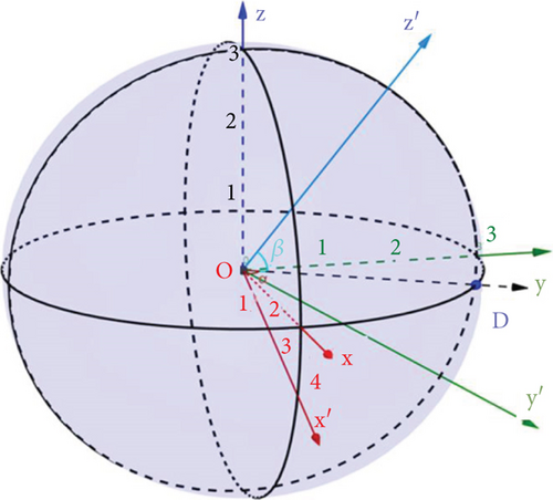
At the same time, taking the spherical center of the reference sphere as the origin and the direction pointing to the observed celestial body as the z-axis, we establish the spatial follow-up coordinate system OX′Y′Z′, as shown in Figure 1. The models in the subsequent articles are established and solved based on this follow-up coordinate system OX′Y′Z′.
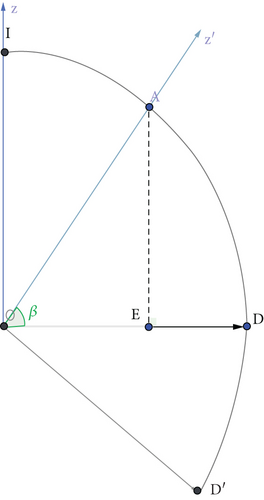
Where variablef is the focal length of the ideal paraboloid, and h is the offset of the paraboloid vertex along the Z′ axis relative to the reference sphere. Obviously, under the working state, the point with the maximum offset of each main cable node in the working area is the vertex.
Since only each main cable node can be used for paraboloid fitting, the optimal approximation model is found by fitting the distribution of the mean square deviation from the reference sphere center to each point, that is, the radial direction deviation. To make the expansion distance of the actuator within the adjustable range, we take h as the variable to find the h value with the smallest overall offset, that is, the smallest overall RMSE, so as to determine the ideal paraboloid.
3.3. Establishment and Solution of Overall Offset Model
Take a point A(x0, y0, z0) in the above follow-up coordinate system and set it as any main cable node in the lighting area on the ball.
After being pulled by the actuator, point A is offset to point A′ on the paraboloid. The radial expansion of the actuator is known; so, we can think that the displacement of main cable node A only moves along the normal direction of the sphere, while the displacement along the tangential direction of the sphere is ignored. According to the actual situation, the paraboloid is close to the spherical surface; so, here we think that the vector AA′ is approximately along the normal direction of the spherical surface, then the line segment AA′ is parallel to the Z′ axis A, and its value is set as d. When the point is located on the inner side of the ideal paraboloid, the deviation value d is positive; otherwise, it is negative.
3.4. Result Analysis
4. Problem Two Model Establishment and Solution
4.1. Research Approach
A follow-up coordinate system has been established according to the direction of the measured celestial body. When the angle of the celestial body is known, the ideal paraboloid in the reference coordinate system can be transformed into an ideal paraboloid with the vertex on the z-axis in the follow-up coordinate system. To study the coordinate changes of each main cable node, the Lagrange operator method is used to solve the shortest distance from the point to the parabola, which is used as the objective function and added constraints to make the actual offset point approach the ideal paraboloid. The constraint conditions include the expansion amount of radial actuator and the variation range of node spacing. According to this condition, the optimization model is established, and the global variables are defined for the variation range of node spacing.5.1 coordinate rotation and solution of ideal paraboloid trajectory equation.
4.2. Theoretical Derivation
The rotation transformation between the reference coordinate system and the follow-up coordinate system is discussed below.
We also choose the follow-up coordinate system to discuss the coordinate offset of each main cable node. Process the coordinates of the main cable node transform it from the reference coordinate system OXYZ to the follow-up coordinate system OX′Y′Z′.
The processed part of the coordinate data is shown in Table 2.
| Node | X | Y | Z | Thea X | Thea Y | Thea Z |
|---|---|---|---|---|---|---|
| A0 | 49.320 026 47 | 36.889 381 35 | -294.018 482 6 | -0.164 181 18 | -0.122 800 87 | 0.978 756 6 |
| B1 | 55.229 444 59 | 45.147 999 76 | -291.807 329 5 | -0.183 874 204 | -0.150 286 726 | 0.971 392 903 |
| C1 | 59.071 297 35 | 33.580 077 66 | -292.614 262 4 | -0.196 623 253 | -0.111 766 87 | 0.974 088 014 |
| D1 | 49.396 380 8 | 26.555 491 25 | -295.118 526 | -0.164 435 398 | -0.088 394 798 | 0.982 419 134 |
| E1 | 39.575 149 93 | 33.781 467 71 | -295.859 369 1 | -0.131 760 932 | -0.112 436 88 | 0.984 884 257 |
| A1 | 43.180 250 62 | 45.272 464 75 | -293.812 901 1 | -0.143 721 369 | -0.150 701 494 | 0.978 076 287 |
| A3 | 49.071 321 78 | 53.521 360 38 | -291.492 125 4 | -0.163 353 742 | -0.178 141 503 | 0.970 351 048 |
| …… | …… | …… | …… | …… | …… | …… |
| E428 | -152.060 690 4 | 187.429 294 9 | -178.852 558 8 | 0.506 172 8 | -0.623 929 324 | 0.595 400 116 |
| E429 | -146.547 628 5 | 195.355 187 4 | -174.930 084 6 | 0.487 849 82 | -0.650 329 634 | 0.582 300 544 |
| E430 | -140.771 871 8 | 203.086 310 4 | -170.820 626 6 | 0.468 615 102 | -0.676 066 534 | 0.568 624 596 |
4.3. Reflector Pane Adjustment Model Based on Discrete Main Cable Node Displacement
To make the main cable node approach the ideal paraboloid as much as possible, a reflector panel adjustment model based on discrete main cable node displacement is established. The first mock exam is the best one in the problem, and the ideal paraboloid is also for the main cable node. The actual paraboloid with triangular panels should have a larger radius of curvature, as shown in Figure 2. Therefore, discrete points to approximate the ideal paraboloid are adopted [31].
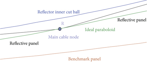
In the follow-up coordinate system, the distance between the actual offset point of the main cable node and the ideal paraboloid is discussed, and the coordinate of the actual offset point closest to the ideal paraboloid under the limiting conditions (i.e., the radial expansion is -0.6 and 0.6, and the change of the distance between adjacent nodes is no more than 0.07%) is found. Therefore, the optimization model is established to find out the adjustment model of the reflection panel based on the displacement of discrete main cable nodes.
In practice, when the actuator pulls the triangular reflector for displacement, there will be a small change in the distance between adjacent nodes, which deviates from the theoretical offset point calculated above, so that the main cable node is not on the ground anchor point and the connecting line of the ball center; that is, the three points cannot be strictly collinear. Therefore, the main cable node and ground anchor point do not move completely along the radial direction in the actual deformation [32, 33].
We take any main cable node A(x0, y0, z0) on the working area of the reference sphere, set the ideal offset point of A point as A′(x′, y′, z′) point, and the A′ point is located on the ideal paraboloid x2 + y2 = 4f(z + h)2. Due to the existence of deviation, we set the actual offset point of A point as A′′(x′′, y′′, z′′) point. Figure 3 shows the geometric relationship between theoretical displacement and actual displacement of main cable node.
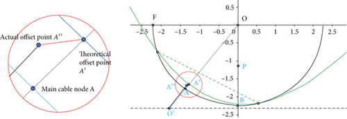
To establish the adjustment model of the main cable node approaching the ideal paraboloid, we use the shortest distance from the actual offset point to the ideal paraboloid as the objective function to establish the optimization model.
At the same time, the topic shows that the small change range of the spacing between adjacent nodes does not exceed 0.07%. Therefore, we add constraints in the process of solving the optimization model, judge in the global situation, and discard the coordinate sequence with the change range exceeding 0.07%.
4.4. Result Analysis
By changing h and f, the objective function value is minimized. Since this problem is a multivariable optimization function, the ordinary traversal method requires a large amount of computation and is affected by the accuracy of the traversal step size; so, the local optimal solution is often obtained. Therefore, the genetic algorithm is used to find the global optimal solution in this problem, and the specific flow chart is shown in Figure 4.
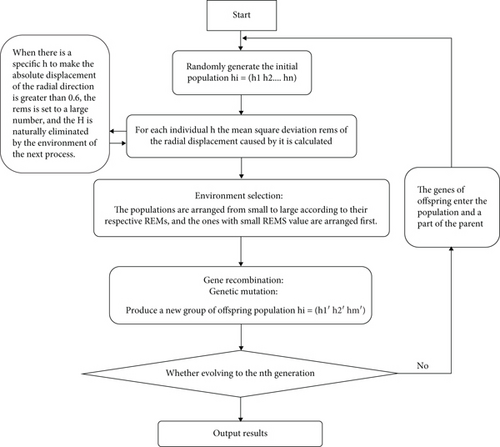
The genetic algorithm steps are roughly as follows:
Step 1. Firstly, the variables are binarized to generate a random initial population, and the fitness value of each individual in the population is calculated.
Step 2. Sort the population individuals according to their fitness and then perform gene recombination and gene mutation in turn to obtain a new population of progeny.
Step 3. Insert the offspring group into the parent group and screen out individuals with excellent fitness values.
Step 4. Enter the next evolution and stop and output the optimal solution when the evolution reaches the formulation of algebra.
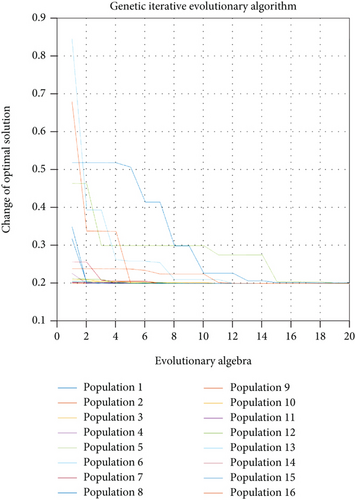
Using the above genetic algorithm and substituting the data in the attachment to solve the optimal offset coordinates of each main cable node, the final optimal solution is h = 300.8169 and f = 140.6192. Substitute h and f into the calculation formula (4) of the deviation d. Since the length does not change with the change of the coordinate system, the value of d is the same as the value in the reference coordinate system. Therefore, it can be obtained that the parabolic trajectory equation of the actual migration is x2 + y2 = 562.4768(z + 300.8169), the average length of the adjacent nodes is 0.0633%, and the average length of the radial shrinkage of the main cable node is 0.20343. According to the solved main cable node coordinates, perform inverse transformation according to the rotation matrix, solve the transformation coordinates in the reference coordinate system, and adjust the main cable node number, position coordinates, and the expansion and contraction amount of each actuator within the 300-meter diameter of the rear reflection surface. The resulting genetic iterative evolution diagram is shown in Figure 5.
5. Receiving Ratio of Feed Cabin Based on Reflector Adjustment Scheme
5.1. Research Approach
According to the active reflector mediation scheme obtained, in order to calculate the effective amount of information received by the feed cabin, the area contacted by the electromagnetic wave can be used as the basis for judging its amount of information. For each triangular reflector, the projection triangle formed when the electromagnetic wave propagates to the plane of the feed cabin through reflection is considered. Since the effective receiving area of the feed cabin is small, about 0.7854m2, it is necessary to judge the area of the projected area. By meshing the plane where the feed cabin is located and decomposing it into a set of points, the effective coverage area of the projection to the feed cabin can be judged according to the distribution of points [34].
5.2. Determination of Receiving Ratio of Feed Cabin after Adjusting Paraboloid
The topic has given that electromagnetic wave signals and reflected signals are regarded as linear propagation; so, their propagation can be considered to obey the optical principle. Since we have rotated the coordinate system, the electromagnetic wave from the observed celestial body can be regarded as a parallel electromagnetic beam of vertical incidence, and its direction vector is set as . We use the size of the area touched by the electromagnetic wave as the basis for judging the amount of information. For each triangular reflecting surface, consider the projection on its plane when the electromagnetic wave received and reflected by its three vertices propagates to the feed cabin located at the ideal parabolic focus. The projection triangle formed by these three projections is the projection area of the electromagnetic wave reflected by the triangular reflective panel, as shown in Figure 6.
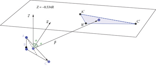
If the normal vector of the triangular unit panel is , then the coordinate expression of is obtained by solving the system of equations as (1, (b/a), (a4 + 2a2b2 + b4 − a2c2 − b2c2/2a3c + 2ab2c)).
Similarly, the coordinates of B and C can also be obtained similarly.
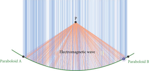
Based on the adjustment scheme of the main cable nodes obtained in the second 4, we can find out the projection of the main cable nodes on the plane of the feed cabin according to the position coordinates of each main cable node in the working area, so that the amount of electromagnetic wave information received by the feed cabin can be calculated, as shown in Figure 7.
5.3. Result Analysis
5.3.1. Determination of the Effective Receiving Area of the Circular Surface of the Feed Cabin
It is known that the effective receiving surface of the feed cabin is a central disk with a diameter of 1 m; that is, the effective receiving area of the feed cabin is small, about 0.7854 m2; so, we need to judge the area of the projected area. If the projected area completely covers the central disk, the effective receiving area is 0.7854 m2; if the projected area does not completely cover the central disk, the effective receiving area is the overlapped area; if the projected area does not cover the center disk, the effective receiving area is 0.
For each point on the circular surface, it is discussed whether it falls inside the projected triangle or on the boundary, and then the problem turns into the problem of whether the point falls inside the triangle. Take any discrete point P as the following discussion [35].
Whether the point P is inside the triangle A′B′C′, the positional relationship between the triangle and the disk can be judged by the barycentric method. The two sides of the projected triangle are used as the direction of a set of two-dimensional basis vectors, and then any point on the plane can be represented by this pair of basis vectors, that is, , Among them, u and v are real numbers, and the positional relationship between point P and triangle A′B′C′ is judged by the values of u and v. The result is shown in Figure 8.
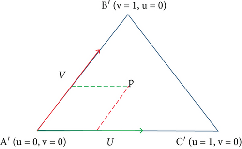
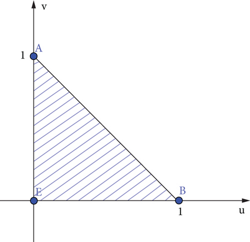
When the value of u and v falls in the shaded part, that is, when the condition is satisfied, the point P falls inside the triangle A′B′C′; otherwise, it is not inside the triangle.
When the point P is inside the triangle A′B′C′, then we think that the point P receives the electromagnetic wave of the panel triangle ABC. It can be seen that N (N = 1290) panels participate in the reflection on the paraboloid with a diameter of 300 meters. Traverse the N panels. Whenever a transmitting panel is mapped to a triangle containing a point on the plane where the feed cabin is located, the number of electromagnetic waves Q received by it increases by 1. When the traversal is completed, the electromagnetic wave reception ratio of this point is λ = Q/N. Then, traverse other discrete points according to the above process. Each discrete point stores the electromagnetic wave reception ratio and draws an image, as shown in Figures 9 and 10.
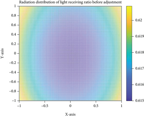
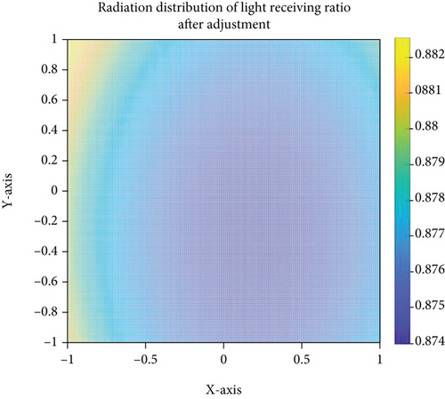
Among them, λi is the reception ratio of discrete points in the circular surface of the feed cabin, and Δ = 0.001 is the step size. According to this principle, the feed cabin can receive the information of 61.628% of the total number of panels before adjustment and 87.752% of the total number of panels after adjustment.
5.3.2. Calculation of Receiving Area Ratio of Feed Cabin
Among them, scabin is the shielding area of the feed cabin, and si is the area of each reflection panel participating in the reflection within a diameter of 300 meters. The complete data can be found in the supporting material, and some data are shown in Table 3.
| Main index node 1 | Main index node 2 | Main index node 3 | Reflector area |
|---|---|---|---|
| A0 | B1 | C1 | 51.359 744 99 |
| A0 | B1 | A1 | 51.360 016 64 |
| A0 | C1 | D1 | 51.357 310 45 |
| A0 | D1 | E1 | 51.357 310 45 |
| …… | …… | …… | …… |
| D245 | D267 | D268 | 65.874 906 28 |
| D246 | D247 | D269 | 62.299 899 98 |
| D246 | D268 | D269 | 65.594 604 13 |
When the reference sphere is not adjusted, the feed cabin can receive the electromagnetic wave signal reflected by about 61.628% of the total panels. The ratio of the area of electromagnetic waves received by the feed cabin to the area of electromagnetic waves received and reflected by the reflector is about 0.636%. After the base sphere is adjusted to a paraboloid, the feed cabin can receive the electromagnetic wave signals reflected by about 87.75% of the total panels. The ratio of the area of electromagnetic waves received by the feed cabin to the area of electromagnetic waves received and reflected by the reflector is about 0.906%.
6. Conclusion and Prospect
- (1)
A follow-up coordinate system with the direction of the observed celestial body as the reference is introduced to find the optimal approximation model for the distribution of the mean square deviation of the radial direction. In order to make the telescopic distance of the actuator within the adjustable range, the overall deviation distribution vector is investigated with h as a variable to find the H value with the minimum overall offset, that is, the minimum overall root mean square error, and the trajectory equation of the ideal paraboloid is determined by the ergodic algorithm
- (2)
The coordinate data of each main cable node are rotated according to the known angle of the celestial body, and the shortest distance from the actual offset point to the ideal paraboloid is obtained by using the Lagrange operator method. Taking this as the objective function, the reflective panel adjustment model of the optimal displacement strategy of discrete main cable nodes is established. The global optimal solution of the offset of each main cable node in the working area is obtained by using genetic algorithm. The mean value of the distance variation between adjacent nodes is 0.0633%, and the average length of the radial contraction of the main cable node is 0.20343
- (3)
The area contacted by the electromagnetic wave is taken as the basis for judging its information content. For each triangular reflecting surface, considering the projection triangle formed when the electromagnetic wave is reflected and propagated to the plane where the feed cabin is located, the effective coverage area of the projection to the feed cabin is judged by using the finite difference method and the center of gravity method. When the reference sphere is not adjusted, the feed cabin can receive the electromagnetic wave signal reflected by about 61.628% of the total number of panels, and the ratio of the electromagnetic wave area received by the feed cabin to the electromagnetic wave surface product received and reflected by the reflector is about 0.636%. After being adjusted to a paraboloid, the feed cabin can receive about 87.75% of the total number of panels, and the ratio of the electromagnetic wave area received by the feed cabin to the electromagnetic wave area received and reflected by the reflector is about 0.906%
However, there are still some shortcomings, mainly including the following: first, the optimization algorithm is complex, the amount of data is large, there are impacts between various data, and the optimization time is long. Secondly, the change of the distance between the main cable nodes cannot be solved in detail and can only be filtered out according to the global control variables. In order to obtain more accurate results, future research will focus on increasing the constraints of the dynamic reflector adjustment optimization model, so as to extend it to more conventional cases.
Conflicts of Interest
The author declares that there are no conflicts of interest regarding the publication of this paper.
Acknowledgments
This study was funded by the Natural Science Foundation of the Higher Education Institutions of Anhui Province (KJ2021A0486).
Open Research
Data Availability
The data in this paper come from question A of the 2021 Contemporary Undergraduate Mathematical Contest in Modeling.


