Finite Element Analysis of CFRP Strengthened Bundle RC Column Subjected to Repeated Impact Load
Abstract
This paper studied numerically the behavior of carbon fiber reinforced polymer (CFRP) confined bundle reinforced concrete (BRC) columns subjected to repeated impact load. To verify the numerical models with previous experimental tests, Abaqus/Explicit based nonlinear finite element (FE) model was developed. Based on the proposed FE analysis, a parametric study was conducted to investigate the effects of different factors such as CFRP confinement, eccentric axial load, bundle reinforcement arrangement, and column height on repeated impact capacity of RC column. While modeling the structural element, concrete damage plasticity (CDP) model is adopted to account for the plastic and strain rate-dependent behaviors of concrete material under impact load. From the nonlinear FE analysis result, it was found that CFRP confinement improved the impact capacity of bundle reinforced concrete column. As column height increased, the column impact resistance was found to decrease. Moreover, when the CFRP strengthened BRC column specimens were repeatedly impacted, the continuous matrix material was severely damaged, while the fiber showed only minor and gradual compressive failures.
1. Introduction
Impact phenomena cover a wide range of applications. A military engineer wants to design strong military works that withstand high-velocity projectiles, vehicle manufacturers require improving the efficiency and safety of their product by understanding how it behaves under impact scenario, and most importantly structural engineer needs to design stable and cost-effective structural elements that resist impact load safely. Concerning this, nowadays advancements in computational tools provide accurate and reliable numerical simulations of dynamic loads such as impact load over the limited empirical and complex analytical methods.
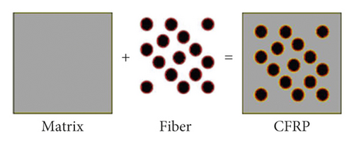
Carbon fiber reinforced polymer (CFRP) is a polymer matrix composite material reinforced by discontinuous carbon fibers (see Figure 1). CFRP has significant advantages including high strength to weight ratio, corrosion and fatigue resistance, and ease of implementation. Due to its superior mechanical properties, CFRP is the best material in strengthening and/or retrofitting different structural elements.
Taiping and Hamid [1] conducted an experimental test on FRP laminate retrofitted RC beams subjected to impact load. The drop weight impact test results presented that the FRP composite laminate significantly increased the impact capacity of the RC beams by reducing the residual deflection and width of the crack. Isaac et al. [2] performed an experimental test to investigate the effect of FRP on the impact response of RC column. It was found that strengthening of RC column with CFRP reduces the peak impact displacement. Sha and Hong [3] studied pendulum impact test of CFRP strengthened RC pier. Their results reveal that the application of CFRP composite wrapping on the RC pier improves the impact load capacity by increasing impact resistance and reducing structural damage. Liu and Xiao [4] examined the impact behaviors of CFRP strip-wrapped RC beams without stirrup. Their result showed that CFRP retrofit enhances the impact resistance of RC beams by reducing their deflection and limiting the damage profile. Dabbagh and Nosoudi [5] investigated numerical analysis of circular, square, and rectangular cross section RC columns confined with CFRP sheets. According to their study, they had found that an increasing CFRP thickness enhances the load-carrying capacities of the RC column. Hou et al.[6] found that strengthening of RC beam with CFRP changes the impact brittle mode failure to ductile. Zhang and Hong [7] reported that, at the same impact energy, FRP wrap improved the impact performance of mid-span and bottom segmental joint impact.
Based on the aforementioned information, the impact problem is a challenging topic for researchers, and hence it is clear that the study on impact performance of the BRC column is limited. In developing countries, compared to the finite element analysis, conducting an experimental study is a typically expensive and time-consuming task. Therefore, the need is evident to investigate numerically the impact performance of CFRP strengthened BRC column subjected to lateral impact load.
In this study, the effect of different parameters such as CFRP, bundle reinforcement, eccentric axial load, and column height on the repeated impact capacity of BRC column was investigated. Moreover, an explicit FE model was developed to verify the numerical model by comparing it with the previous experimental test result.
2. Finite Element Analysis
2.1. Description of the Study
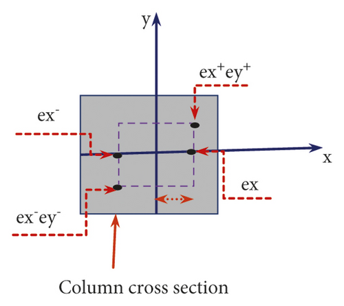
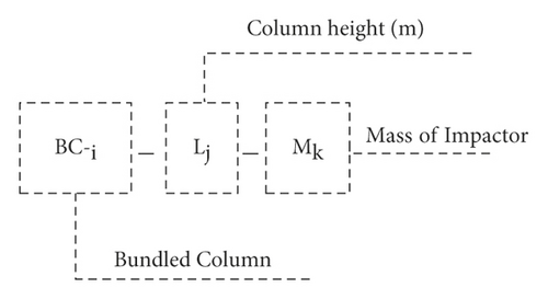
The accuracy of the numerical modeling was validated by using previous experimental tests conducted by Yanyan and Hong [3]. Then, to understand the impact behavior of RC columns, several 400 × 400 mm2 square column specimens have been modeled. The effect of different variables, namely, CFRP confinement, four different bundle reinforcement distributions (i.e., normal (BC-1), two bundles (BC-2), three bundles (BC-3), and four bundles (BC-4)), four eccentric axial loads (refer to Figure 2(a)), and three different column heights, was investigated. To identify the parameters easily, during FE simulation, the RC column specimens are nominated as in Figure 2(b).
2.2. Finite Element Discretization
The numerical model was simulated using Abaqus/Explicit package nonlinear FE analysis. As shown in Figure 3, concrete material was modeled using a 3D eight node linear brick element with reduced integration (C3D8R). Two-node linear 3D truss (T3D2) elements were implemented for the steel reinforcement bar. Similarly, the CFRP, epoxy risen, and lateral impactor were also modeled with a 4-node shell element (S4R), 8-node 3D cohesive element (COH3D8), and four-node 3D bilinear rigid quadrilateral (R3D4) elements, respectively. Moreover, the surface to surface explicit contact algorism was employed for the RC column and impactor interaction. Finally, a perfect bond was assumed to be the interaction between concrete (i.e., host region) and reinforcement bar (i.e., embedded region).

2.3. Material Model
2.3.1. Concrete
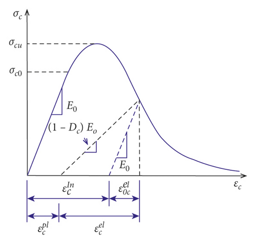
400 × 400 mm2 square RC column with different bundle reinforcement distributions was modeled in Abaqus/Explicit. A concrete grade having a compressive strength of 38 MPa was considered [8]. While simulating the numerical models, to account for the elastic-plastic behavior of concrete material, the concrete damage plasticity model (CDP) was employed. The CDP model is a plasticity based constitutive model that requires defining strain rate decomposition, stress stain relation, stiffness degradation mechanisms associated with each failure mode, hardening rule, flow rule, and stiffness recovery effects during load reversals. As shown in Figure 4, it is considered that the main failure mechanisms of concrete are tensile cracking and compressive crushing [9].
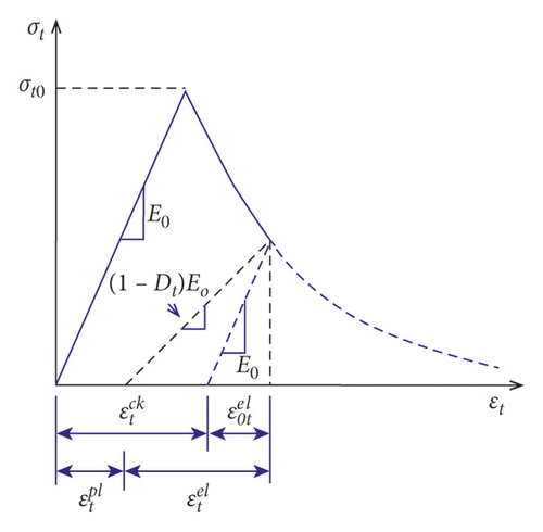
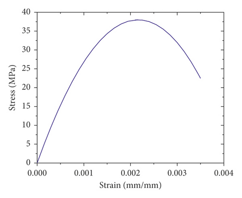
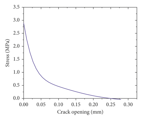
(2) Concrete Tensile Behavior. Once concrete material has been cracked, the postfailure tensile behavior can be modeled with tension stiffening, a phenomenon that defines the interaction of reinforcement with concrete and strain softening. In the CDP model, tension stiffening of concrete can be specified by either postfailure stress-strain relation or fracture energy cracking criterion. In this study, as shown in Figure 5(b), to describe the tensile behavior of cracked concrete section, the fracture energy concept (i.e., stress versus crack opening) was employed [11, 12].
2.3.2. Steel Reinforcement Bar
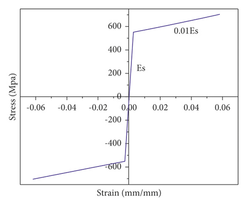
The RC columns were reinforced with 20 mm deformed bars and 8 mm stirrups having yield strengths of 550 MPa and 460 MPa, respectively. Since steel reinforcement is a homogeneous material, a single stress-strain relationship is sufficient to define the steel material properties needed in the nonlinear FE model. As recommended by Kachlakev et al. [13], the plastic part of steel behavior can be modeled as an elastic perfectly plastic material using a strain hardening ratio of 0.01 (see Figure 6).
2.3.3. CFRP
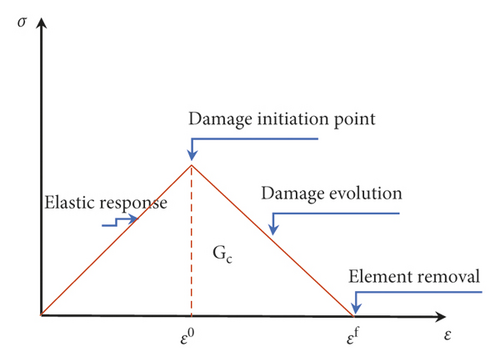
CFRP is a synthetic material consisting of two parts, namely, the fiber reinforcement that provides strength to the composite and the matrix as a binder of the fibers. When CFRP is subjected to impact load, it undergoes internal damages in the form of resin matrix cracking, fiber fracture, or interlaminar delamination. Thus, the damage model of CFRP material requires specifying three material responses: (a) undamaged (i.e., linearly elastic) response, (b) damage initiation criterion, and (c) damage evolution response (see Figure 7) [9]. While the elastic phase of the lamina was defined using modulus of elasticity, Poisson’s ratio, and the shear modulus of elasticity in all directions, the damage initiation was modeled based on Hashin's damage model [14]. Finally, the damage evolution response of the fiber was adopted based on the fracture energy dissipated during the damage process.
Hashin's damage model considers four different damage initiation mechanisms: fiber rupture in tension, fiber buckling in compression, matrix cracking under transverse tension and shearing, and matrix crushing under transverse compression and shearing as described correspondingly from equation (6) to equation (9). Furthermore, the input values for Hashin’s damage criterion are summarized in Table 1.
| Parameters | Elastic property | |||||||||||||
|---|---|---|---|---|---|---|---|---|---|---|---|---|---|---|
| E1 | E2 | ν12 | G12 | G13 | G23 | |||||||||
| Unit | MPa | — | MPa | |||||||||||
| Value | 205,000 | 25,000 | 0.33 | 1 × 10⁻⁶ | 1 × 10⁻⁶ | 3,000 | ||||||||
| Parameters | Damage initiation | Damage evolution | ||||||||||||
| XT | XC | YT | YC | SL | ST | GT1C | GC1C | GT2C | GC2C | |||||
| Unit | MPa | N/m | ||||||||||||
| Value | 2,760 | 552 | 1 × 10⁻⁶ | 1 × 10⁻⁶ | 50 | 1 × 10⁻⁶ | 91,600 | 79,900 | 1 | 1 | ||||
2.3.4. Cohesive Element
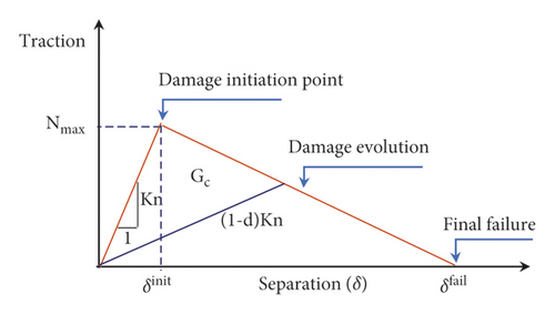
- (1)
Maximum nominal stress criterion (MAXS):
(11) - (2)
Maximum nominal strain criterion (MAXE):
(12) - (3)
Quadratic nominal stress criterion (QUADS):
(13) - (4)
Quadratic nominal strain criterion (QUADS):
(14) -
where σn, σs , and σt are nominal stresses, Nmax, Smax, and Tmax denote the maximum stresses, εn, εs&εt denote the nominal strains, and denote the maximum strains in pure normal mode, first shear direction, and second shear directions, respectively. Moreover, the mechanical properties of the adhesive element are listed in Table 2.
| Parameters | Linear elasticity | Damage initiation | Damage evolution | ||||||||
|---|---|---|---|---|---|---|---|---|---|---|---|
| Density | Knn | Kss | Ktt | Ea | σn | σt | σs | Gn | Gs | Gt | |
| Unit | kg/m3 | N/m3 | MPa | N/m | |||||||
| Value | 1300 | 23.6 | 23.6 | 4,820 | 31.28 | 31.28 | 31.28 | 1,000 | 1,250 | 1,250 | 1,250 |
2.4. Strain Rate
As compared to the static load case, the mechanical properties of most material under dynamic load are quite different. While the static strain rate is found in the range of 10−6 to 10−5 S−1, the impact load is associated with strain rate in the range of 10° to 102 S−1 [16]. For RC structures subjected to impact load (i.e., high strain rate), the strength of concrete and steel materials is enhanced. During the numerical simulation, the strain rate can be accounted with the dynamic increase factor (DIF) [17]. The dynamic increase factor of a given material can be well defined as the ratio of dynamic strength to the strength at quasistatic strain rates.
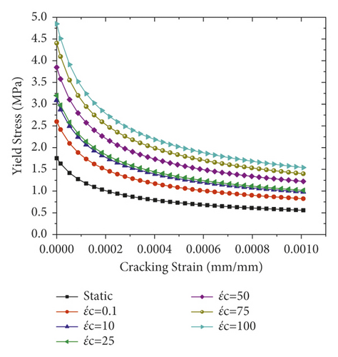
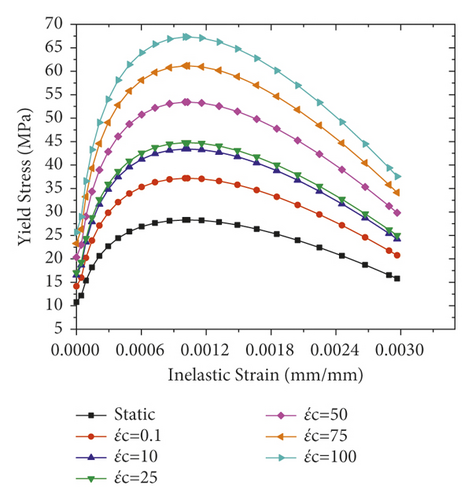
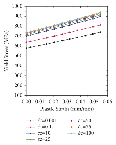
Compared to steel reinforcement bar and concrete material, the strength increment of CFRP sheet due to the strain rate effect is insignificant [19]. Therefore, in the current study, the strain rate effect of CFRP is not considered.
3. Results and Discussions
3.1. Validation
To verify the numerical model, the results obtained from the FE analysis were compared with the experimental test. The impact force-time histories of FE analysis results along with experimental data are presented in Figure 11. As shown in Figures 11(a)–11(e), for all impact cases (i.e., 1st to 5th impact), the numerically obtained peak impact forces were consistent with the experimentally measured test results.
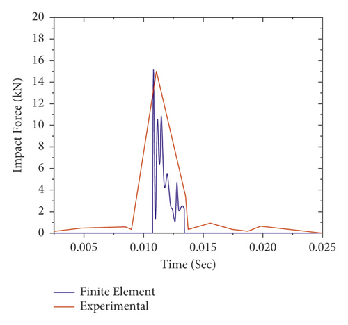
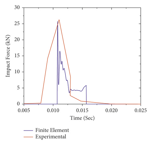
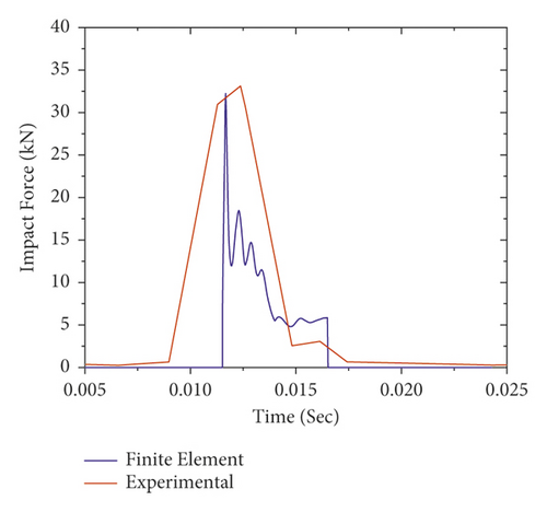
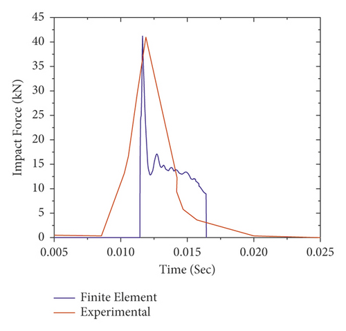
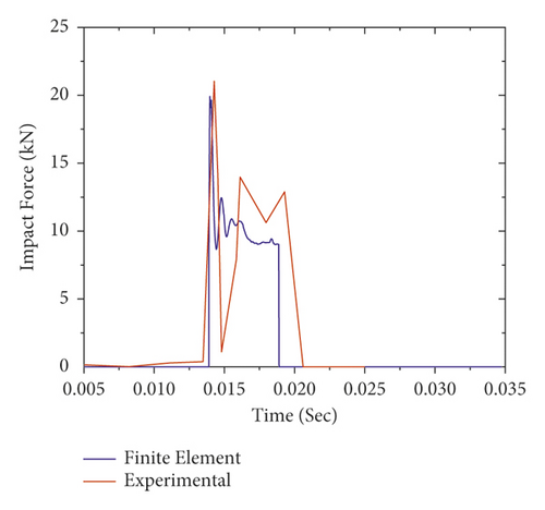
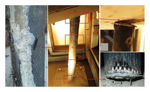
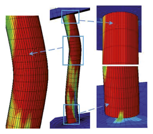
Figure 12 also validates the failure profiles of the CFRP confined FE analysis and the experimental test results of the RC column at the failure load stage. As shown, a good agreement is observed between the failure modes of nonlinear FE analysis and experimental results of the RC column. Overall, this indicates that the nonlinear FE analysis can provide a reasonable prediction of RC column impact behavior. Therefore, in this study, Abaqus/Explicit package was employed to investigate the behavior of the BRC column under repeated impact load.
3.2. Effect of CFRP Confinement on Impact Behavior of BRC Columns
Based on developed nonlinear FE simulations, this section presents the effect of CFRP confinement on the impact performance of BRC columns. For comparison purposes, except for the CFRP laminate, other material properties and geometric dimensions of the specimens are kept the same as in case of unstrengthened columns.
3.2.1. On the Impact Capacity
Figure 13 demonstrates the impact force-time histories of different BRC columns with variable initial velocities during the first impact. Since the impact energy is amplified, it is obvious that as the impact velocity increased, the peak impact force also increased. In addition, as shown in Figure 13(b)), good impact capacity was observed in the case of two-bundle bars (BC-2) compared to other column specimens.
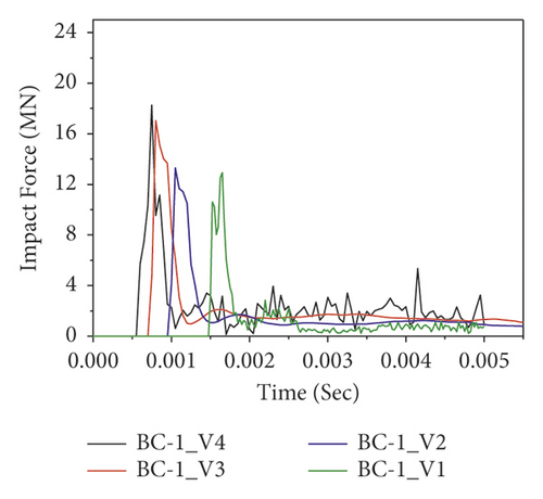
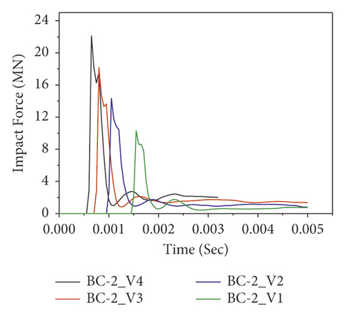
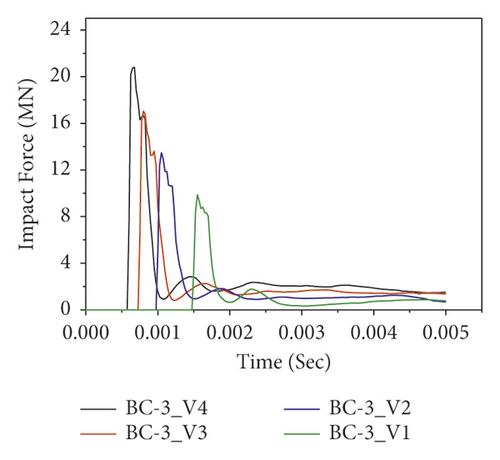
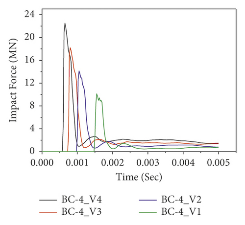
Figure 14 shows the impact force versus time of CFRP confined BRC columns. Compared to the impact capacities of as-built columns, the nonlinear FE analysis result revealed that the lateral confinement of CFRP improved the impact capacities of BRC columns. For example, at impact velocity of 15 m/s, the corresponding impact force improvements due to CFRP confinement are 33.76%, 36.39%, 39.86%, and 34.37% for BC-1, BC-2, BC-3, and BC-4 specimens, respectively. Moreover, the effect of CFRP confinement on the impact behavior of the BRC column is depicted in Figure 15.
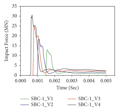
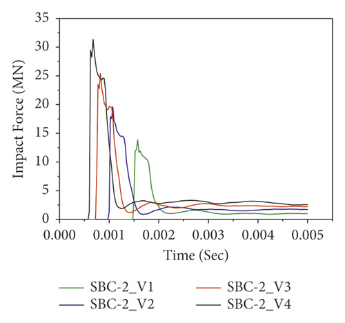
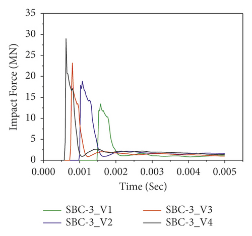
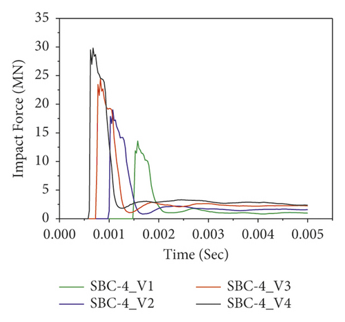
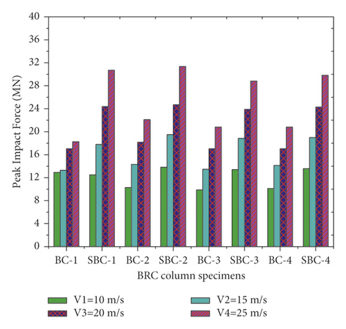
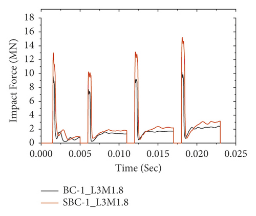
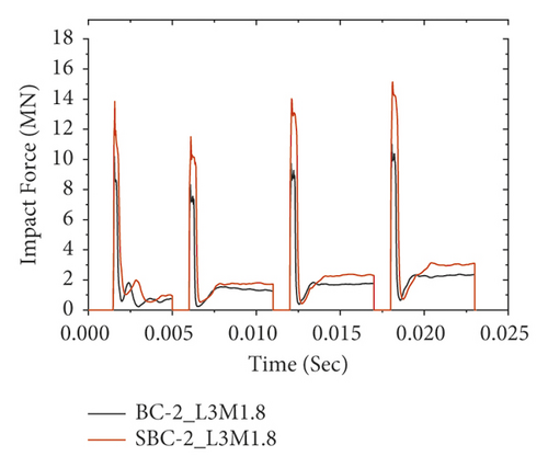
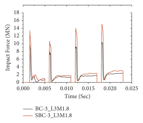
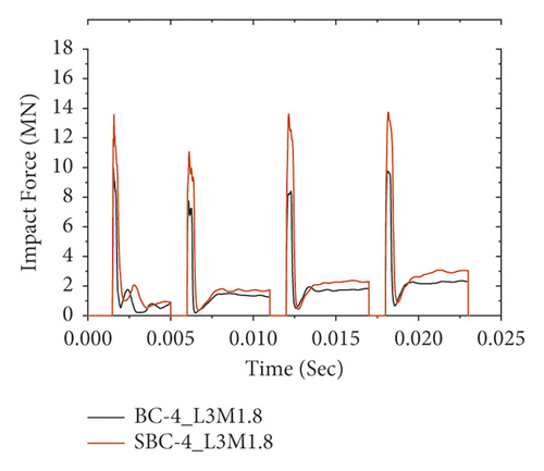
Figure 16 also reveals the impact force-time histories comparisons of BRC columns with and without CFRP wrap under repeated lateral impact. As shown in the figures, it is found that, at the same impact velocity, the maximum impact force of unstrengthen columns is lower than the CFRP strengthened BRC columns. This is because the CFRP confinement increases the column stiffness, and hence it improves the impact load resisting capacity of BRC columns. Compared to the first and second impact conditions, the peak impact force improvement due to CFRP wrapping is high on the 3rd and 4th impact.
3.2.2. On Damage Mode
RC structural members subject to impact load may damage either local failure at the impact zone or overall failure of the member. Local damage tends to be a common issue concerning RC plates while overall failure is associated with RC beams and columns subjected to impact load. As the single impacted unstrengthened BRC columns failed with the local shear failure, the repetitively impacted specimens were damaged by global failure [8].
In this study, as shown in Figure 17, when the impactor hit the BRC column at first impact with an initial velocity of 10 m/s, trivial cracks were originated at the tension face of the RC column. When the impact energy increased on the subsequent impacts, the tensile stress exceeds the tensile strength of concrete. At this stage, while the steel reinforcement carries the tensile stress of the unstrengthened cracked column, both steel reinforcement and CFRP laminate resist the cracked section of the CFRP confined BRC column. Therefore, compared to the CFRP wrapped specimens, the FE analysis result showed that for the same impact velocity the unstrengthened columns were damaged severely due to compression crashing and tensile cracking of concrete near the impact zone. The severe damage profiles at the third and fourth impacts of unstrengthened BRC columns were to some extent limited with CFRP confinement (refer to Figure 17(b)). This indicates that CFRP improved the impact-resisting capacity of RC columns by increasing the column stuffiness.
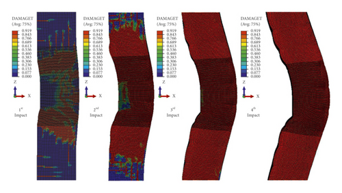
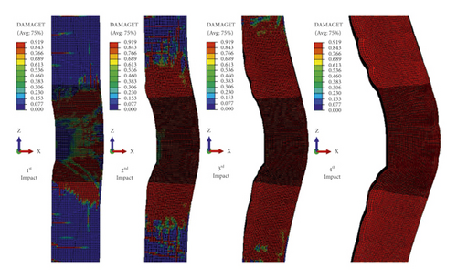
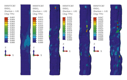
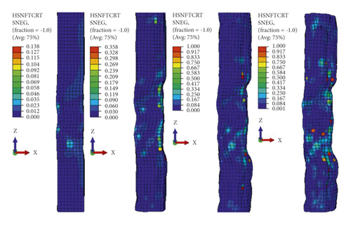
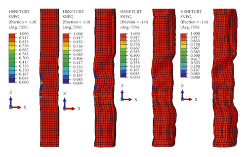
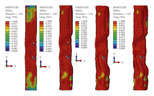
As stated previously, Hashin damage initiation of the laminate may fail due to fiber compression buckling, fiber tension fracture, matrix tensile cracking, and/or matrix compressive crushing. Figure 18 demonstrates the damage initiation profiles of the CFRP sheet from the first impact to the fourth impact. As it can be seen, the damage modes were described by using compressive buckling and tensile ruptures of fiber and matrix materials separately. The matrix material was severely damaged while the fiber showed only minor and gradual compressive failures. Compression fiber damage initiation criterion (maximum allowable value of one) of the CFRP sheet was reached after the third impact (refer to Figure 18(b)). However, as shown in Figure 18(a)), the tensile fiber failure does not reach damage initiation. This is because CFRP has high strength in tension. On the other hand, as shown in Figures 18(c) and 18(d), the continuous matrix was highly damaged in both tension cracking and compression crashing from the first impact.
3.3. Eccentric Axial Load
To understand the effect of eccentric axial load on impact performance BRC column, axial loads were employed by allowing some eccentricities from the center of the column cross section. Four different types of eccentricities, namely, positive x-axis (i.e., ex+), positive x-axis and positive y-axis (ex+ey+), negative x-axis (ex−), and negative x-axis with the negative y-axis (ex-ey-) are considered (refer to Figure 2(a)). In all cases, the axial load was shifted by 100 mm from the center of the RC column cross section.
The computed impact force histories of different BRC column models with variable axial load eccentricities are portrayed in Figure 19. As seen, it was found that except for three-bundle reinforcement distribution all other eccentrically loaded BRC column specimens (i.e., normal, two bundles, and four bundles) show good impact capacity in case of negatively x-axis (ex−) eccentric axial load. This is because the negatively x-axis eccentric axial load produces a bending moment that deflects the impacted column towards the impacted column face direction. Since concrete is good in compression, this moment improved the transverse impact capacity by increasing the column stiffness. On the other hand, in the case of three-bundle RC columns, good impact resistance was observed when the axial load was positioned at eccentricities of ex+ and ex-ey-. This indicates that the corner bundle reinforcement of the three-bundle system is resistant for both x-axis and y-axis eccentric axial loads.
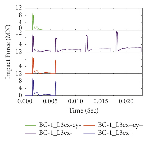
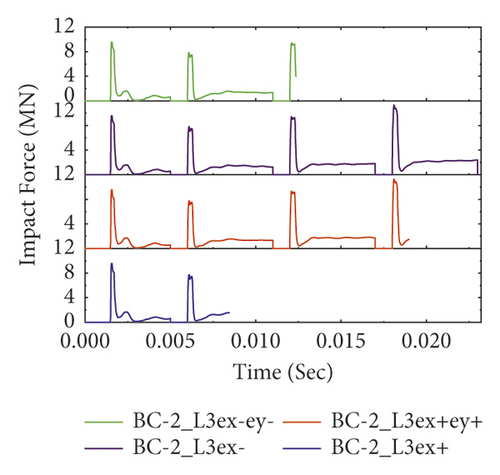
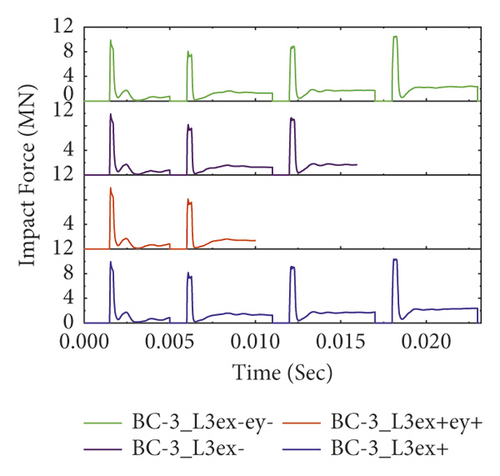
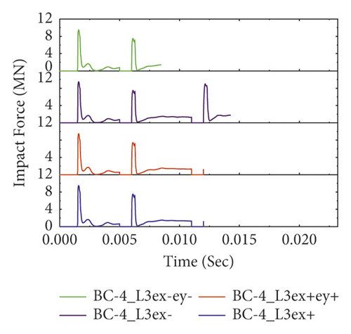
However, compared to pure axially loaded BRC columns, it was found that the impact capacities of BRC columns with eccentric axial load were significantly reduced [8]. This is because the additional bending moment generated from eccentric axial load reduces the column's impact capacity. Furthermore, compared to the other bundle bar distributions, two bundles showed good impact capacity; refer to Figure 19(b).
3.4. Effect of Column Height
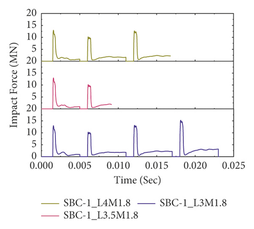
The effect of column height on the impact performance of as-built BRC columns is shown in Figure 20. The numerical result revealed that the column height has no remarkable effect on the peak impact forces of BRC columns. But, as the height of the column increased from 3 m to 4 m, the impacted BRC column specimens failed with the least repeated blows before reaching at the end of the fourth impact. This is because as the height of the column increased its stiffness was reduced and played additional moment (i.e., becoming slender and liable to buckle) and consequently lowered the impact capacity of the columns. On the other hand, compared to other bundle reinforcement distributions, two-bundle systems showed good impact resistance (see Figure 20(b)).
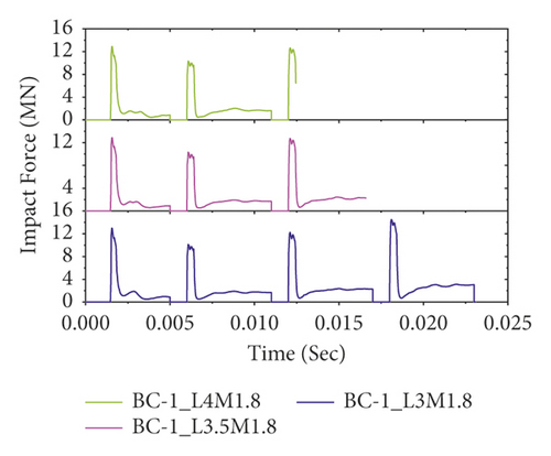
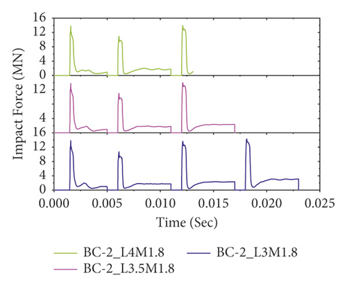
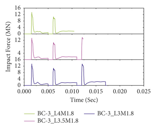
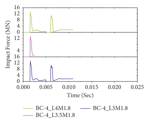
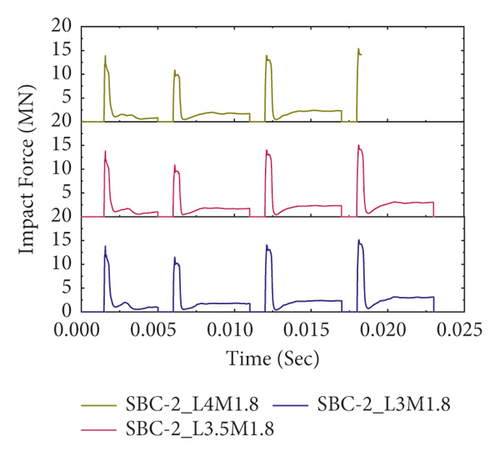
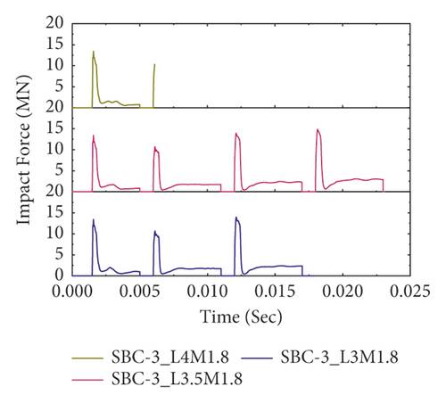
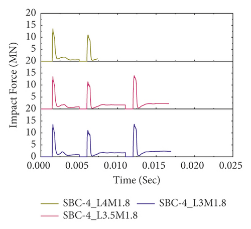
Figure 21 also illustrates the effect of column height on repeated impact behaviors of CFRP confined BRC columns without changing other parameters. Except for normal reinforced concrete column specimens (see Figure 21(a)), compared to unstrengthened columns, CFRP confinement improved the impact capacity of bundle reinforced columns. Overall, while impact performance was reduced with increasing column height, CFRP confinement improved the repeated impact capacity of bundled RC columns.
4. Conclusion
- (1)
During validation, it was found that the repeated impact FE analysis results showed good agreement with previous experimental measured data of the same member. This indicates that nonlinear FE analysis can provide a reasonable prediction of RC column impact behavior.
- (2)
By strengthening with CFRP sheet, the impact capacity of BRC column is significantly improved compared to the as-built column specimens. Additionally, the carbon fibers showed only minor and gradual compressive damages, while the matrix material is severely failed to start from the first impact. From this, it can be concluded that the high strength of the CFRP sheet is associated with discontinuous fibers.
- (3)
Based on the FE analysis results, compared to the pure axial load eccentrically loaded BRC column specimens showed lower repeated impact capacity. On the other hand, except for three-bundle bars, all other eccentrically loaded BRC column specimens (i.e., normal, two bundles, and four bundles) showed good impact capacity in case of negatively x-axis (ex−) eccentric axial load.
- (4)
The numerical result also revealed that column height has no remarkable effect on the peak impact forces BRC columns. However, as the height of the column increased, the impacted BRC column specimens failed with the least repeated blows before reaching the end of the fourth impact.
- (5)
Under the same impact energy, two-bundle RC columns showed good impact resistance capacity over the normal (i.e., without bundle), three-, and four-bundle reinforced concrete columns.
Abbreviations
-
- BRC:
-
- Bundle reinforced concrete
-
- CFRP:
-
- Carbon fiber reinforced polymer
-
- CDP:
-
- Concrete damage plasticity
-
- DIF:
-
- Dynamic increase factor
-
- FE:
-
- Finite element
-
- RC:Reinforced concrete:, and :
-
- Reinforced concrete:σ11, σ22, and τ12:Normal and shear fiber effective stress (MPa)
-
- XT&Xc:
-
- Longitudinal tensile and compressive fiber strength (MPa)
-
- YT, Yc:
-
- Transverse tensile and compression strength (MPa)
-
- ST, Sc:
-
- Longitudinal and transverse shear strength (MPa)
-
- Gn, Gs, and Gt:
-
- Normal, first shear, and second shear direction fracture energies (N/m)
-
- Knn, Kss, and Ktt:
-
- Normal, first shear, and second shear direction stiffness values (N/m3)
-
- σn, σs, σt:
-
- Normal, first shear, and second shear direction nominal stresses (MPa)
-
- δn, δs , δt:
-
- Normal, first shear, and second shear direction separations (mm)
-
- εn, εs&εt:
-
- Normal, first shear, and second shear direction nominal strains (mm/mm)
-
- , :
-
- Total, elastic, damaged elastic, and plastic concrete tensile strains (mm/mm)
-
- σc, σt:
-
- Compressive and tensile concrete stresses (MPa)
-
- , :
-
- Inelastic strain and cracking strain (mm/mm).
Disclosure
This research was made as partial fulfillment of the requirements for the award of Master of Science in structural engineering.
Conflicts of Interest
The author declares that there are no known conflicts of interest.
Authors’ Contributions
The author is responsible for the content and writing of this article.
Acknowledgments
The author would like to acknowledge Addis Ababa Science and Technology University (AASTU) Mining Engineering Department Head for providing support to perform the FE simulation of the study.
Open Research
Data Availability
Additional data used to support the findings of this study are available from the author upon request, who can be contacted at [email protected].


