Inertial Forces and Torques Acting on a Spinning Annulus
Abstract
The many publications related to the gyroscope theory consider the action of the inertial torques on the spinning disc. All of them have simplified expressions for the inertial torques and mathematical models of the gyroscope motions do not validate by practice. Recent research in the theory of the gyroscopic effects for rotating objects solved problems with mathematical models for interrelated inertial torques generated by the spinning disc, bar, and ring and their motions. Practitioners of engineering designed gyroscopic devices with spinning rotors whose geometry can be an annulus or similar designs. Such spinning annulus generates inertial torques whose expressions differ from the disc bar and ring and hence another mathematical model describes the motions of the gyroscopic devices. The value of gyroscopic effects of the devices with spinning annulus is bigger than for the disc-type rotor. This manuscript presents mathematical models for the inertial torques generated by the spinning annulus and the interrelated angular velocities of the gyroscopic devices about axes of rotation.
1. Introduction
The gyroscopic effects in engineering mechanics are the most complex problems that are being unsolved for a long time [1–5]. Beginning from the Industrial Revolution, scientists yield only partial analytical solutions but did not solve the entire gyroscopic effects. For practical applications were worked out numerical models with the expensive software for gyroscopic effects. The physics of the gyroscopic effects of the simple spinning disc remained unexplained and mysterious for a couple of centuries [6–10]. Scientists and researchers of our time continue to describe gyroscopic effects without success which can be seen in many publications each year [11–19]. Recent investigations of the gyroscopic effects showed their nature is more complex and based on several physical principles that were discovered at different times. Scientists of 18-19 centuries could not solve gyroscopic effects in principle because the concept of mechanical energy conservation was formulated at the beginning of twenty century. From this time, researchers have all the analytical tools for formulation of the gyroscope theory but did not do it.
The latest studies of the physics of the gyroscopic effects yield mathematical models for the inertial torques and the interrelated dependency of the angular velocities of the spinning disc motions about axes of rotation. The solution to gyroscopic effects is based on the principle of mechanical energy conservation [20–22]. The method of deriving mathematical models for inertial torques shows the action of the system of the centrifugal, Coriolis forces generated by the rotating mass, and the change in the angular momentum of the spinning disc. The dependency of the angular velocities of the spinning disc around axes of motions interrelates the inertial torques. Table 1 presents the expressions of inertial torques acting on the spinning disc and the dependency of the angular velocities of it's motions.
| Type of the torque generated by | Acton | Equation |
|---|---|---|
| Centrifugal forces | Resistance | Tct = (4/9)π2Jωωx |
| Precession | ||
| Coriolis forces | Resistance | Tcr = (8/9)Jωωx |
| Change in angular momentum | Precession | Tam = Jωωx |
| Dependency of angular velocities of spinning disc rotations about axes | ωy = (8π2 + 17)ωx | |
The practice tests validate the action of the system of the interrelated inertial torques on the spinning disc. Practitioners should use the derived method for the modeling of the gyroscopic effects for any designs of the spinning objects [22]. The mathematical models for the inertial torques generated by the centrifugal and Coriolis forces and the change in the angular momentum acting on the spinning flat annulus and its interrelated motions around two axes are present as the contribution of the manuscript.
2. Centrifugal Forces and Torques Acting on a Spinning Annulus
The method for the analytical solution for all inertial torques acting on the spinning disc is described in several publications [21, 22]. The inertial torques are generated by the distributed mass elements of the spanning disc disposed on the circle of 2/3 of its radius. This method can be applied to rotating objects of different forms. For the annulus, the radius of the disposition of the distributed mass elements on the circle should be defined. The rotating mass elements produce the plane of centrifugal forces of the spinning annulus around axis oz with an angular velocity of ω in a counter-clockwise direction considered in Figure 1. The mass element m is disposed on the circle of radius r which is perpendicular to the axis of the spinning annulus.
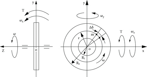
The radius r of disposing of the mass elements of the annulus is defined from the truncated sector with the small angle Δδ and the arcs of the external and internal radii Re and Ri, respectively. The rotating mass elements generate centrifugal forces. The action of the external torque to the spinning annulus has manifested the inclination of its plane with the rotating centrifugal forces and the turns of the annulus around axes. These motions are presented at the Cartesian 3D coordinate system Σoxyz in Figure 1. The external torque applied to the spinning annulus generates several inertial torques (Figure 2).
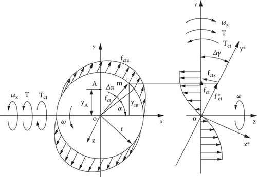
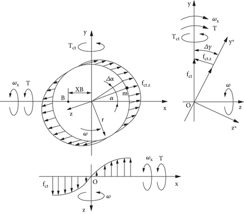
The plane of the rotating centrifugal forces turns around axis ox along the diameter line and changes in the directions of centrifugal force vectors fct of the mass elements. The inclined plane of rotating centrifugal forces on angle Δγ around axis ox is presented in the plane xoy∗. The action of the centrifugal force vectors fct is radial and their components f∗ ct produce the torques around axes ox and oy. The values of torques acting around axis ox are maximal at 90o and 270o and zero at 0o and 180o (Figure 2(a)). The values of torques acting around axis oy are maximal at 0o and 180o and zero at 90o and 270o (Figure 2(b)). The integrated product of the components’ vector of the centrifugal forces fct.z and their radii relative to axes ox and oy give the torques Tct acting around two axes. The torque acting around axis ox resists the action of the external torque T. The torque acting around axis oy turns the spinning annulus in the counter-clockwise direction.
- (i)
Around axis ox
(3) - (ii)
Around axis oy
(4)where fct = mrω2 = (Mrω2/2π)Δδ is the centrifugal force of the mass element m; m = (M/2πr)Δδr = (M/2π)Δδ in which M is the mass of the annulus; Δδ is the sector’s angle of the mass element’s disposition; α is the angle of the mass element’s disposition; Δγ is the angle of turn for the annulus plane, sinΔγ = Δγ is the trigonometric identity for the small values of the angle.
- (i)
About axis ox
(11) - (ii)
About axis oy
(12)
- (i)
About axis ox
(13) - (ii)
About axis oy
(14)
- (i)
About axis ox
(15) - (ii)
About axis oy
(16)where all components are as specified above.
3. Coriolis Forces and Torques Acting on a Spinning Annulus
The Coriolis acceleration and force generated by mass elements are revealed when the spinning annulus turns around axis perpendicular to its axle. The integrated Coriolis force produced by the rotating mass elements of the annulus generates the torque counteracting the external torque [10]. Figure 3 shows the rotation of the mass element m of the annulus that turns on the angle Δγ around axis ox. The turn of the annulus around axis ox changes the direction of the tangential velocity vectors of mass elements. The change in the tangential velocity of mass elements produces the acceleration in which a product with a mass yields the Coriolis forces of the mass elements, where ΔV = VsinΔγ, V = rcosα × ω, and sinΔγ = Δγ for the small angle (Figure 3). The maximal changes of the velocity vectors V∗ are on the line of axis ox. The tangential velocity V whose vector is parallel to axis ox, i.e., on 90o and 270o does not change. The changes in tangential velocity vectors are presented by the components Vz that are parallel to the annulus axle oz.
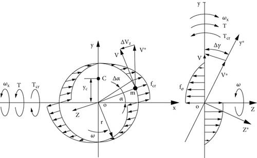
The differential form of changes in tangential velocity vectors is dV/dt = az and change in the angle of rotation around axis ox is dγ/dt = ωx.
4. Attributes of Inertial Torques Acting on a Spinning Annulus
The load torque applied to the spinning annulus produces the system of the inertial torques generated by the rotating mass [22]. Among them is the change in the angular momentum of a spinning disc, which is Euler’s fundamental principle of gyroscope theory [1–5]. The motion of the spinning annulus around axis oy (Figure 3) manifests the change in the annulus angular momentum in the counter-clockwise direction which is called precession. The expression of the change in the angular momentum is Tam = Jωωx where all components are presented above. The system of the inertial torques produces the resistance and precession torques and motions of the spinning annulus around axes of the rotation. Table 2 represents expressions of the inertial torques generated by pseudo forces of the spinning annulus.
| Type of the torque generated by | Action | Equation |
|---|---|---|
| Centrifugal forces, Tct | Resistance |
|
| Precession | ||
| Coriolis forces, Tcr | Resistance |
|
| Change in angular momentum, Tam | Precession | Tam = Jωωx |
| Dependency of angular velocities of spinning disc rotations about axes |
|
|
The external torque T generates all inertial torques that depend on the mass moment of the annulus’s inertia J, its angular velocity ω, and the angular velocity ωx of the spinning annulus about axis ox.
The action of all torques around axes ox and oy on the spinning object is shown in Figure 4 for the given symmetrical disposing of its supports [22]. The interrelated action of the inertial torques is considered for the horizontal disposition of the spinning object.
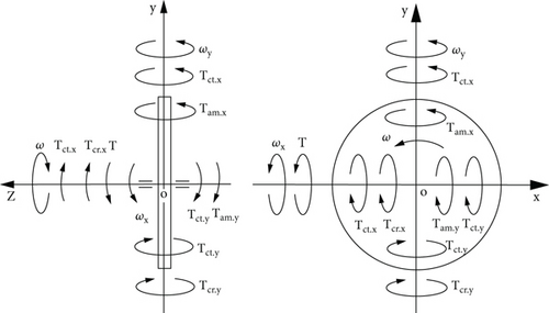
The expressions of the inertial torques and their action, and the dependency of interrelated angular velocities of the spinning annulus around axes are presented in Table 2.
The expressions of torques and the dependency angular velocities (Table 2) formulate the mathematical models for the motions of the gyroscopic devices with the annulus rotor. Comparative analysis of formulas for the spinning annulus shows when its internal radius Ri =0, all of them are converted to the formulas for the disc-type rotor presented in Table 1. This fact validates the mathematical correctness of the formulas. The values of formulas in Table 2 give results bigger than the formulas in Table 1.
5. Working Example
- (i)
The torque Tct generated by the centrifugal forces
(34) - (ii)
The torque generated by Coriolis Tcr forces
(35) - (iii)
The torque Tam of the change in the angular momentum
(36) - (iv)
The angular velocity of precession
(37)
The comparative results of the dependency of the angular velocities rotation around axes of motions for the annulus and disc-type rotor show their big differences. The radius of disposition of the distributed mass of the annulus is bigger than for the disc-type rotor. Analysis of them yields the spinning annulus generates bigger values of the inertial torques and the dependency of the angular velocities than the spinning disc-type rotor.
6. Results and Discussion
Gyroscopic effects are remaining as sophisticated mathematical problems because the inertial torques generated by the rotating mass depend on the geometry of the spinning objects. The practice of engineering designs of the gyroscopic devices shows different geometry of their main components which are the rotors. The value of the inertial torques generated by the spinning rotors depends on their technical data. The working example shows the spinning annulus generates bigger values of the inertial torques and the dependency of the angular velocities than the disc-type rotor. This result gives the tip for the practitioners to design gyroscopic devices with a high value of the inertial torques and the angular velocity of precession. Practitioners can design gyroscopic devices with a necessary output of technical data that depends on the geometry of the spinning rotor. This result opens a new analytical approach to finding optimal designs of the spinning rotor that respond to the quality of gyroscope work.
7. Conclusion
Aerospace and engineering industries try to solve gyroscopic problems and find optimal designs for gyroscopic devices that give the necessary technical data. The new theory of gyroscopic effects for rotating objects opens new methods for computing the technical data for gyroscopic devices. The method for deriving mathematical models for the gyroscopic effects enables finding the output data of gyroscopic devices that depend on the geometry of the main unit which is the spinning rotor. Optimization of the rotor’s design by criteria of the aerospace industry is a new direction for investigations in engineering. The fundamental principles of the theory of gyroscopic effects for rotating objects and methods enable solving them in engineering. The known numerical modeling for gyroscopic effects with expensive software is going past and engineering science receives new analytical methods.
Conflicts of Interest
The authors declare that they have no conflicts of interest.
Open Research
Data Availability
The authors declare that the data supporting the findings of this study are available within the article. R. Usubamatov wrote the mathematical models of inertial torques. S. Kapayea corrected the text and references.


