Static Characteristics of Improved Composite Box Girder with Corrugated Steel Webs
Abstract
In order to accurately calculate the cross-sectional stresses and deflections of the improved composite box girder with corrugated steel webs, the control differential equations and boundary conditions are established based on the energy variational principle, taking into account the effects of corrugated steel web properties, shear lag, and shear deformation. A cantilever composite box girder is used as a numerical example. The influence of width span ratio and corrugated steel web bending angle on the shear lag and fold effect is analyzed. The results show that the analytical solution is in good agreement with the finite element solution. A shear lag effect and a negative shear lag effect exist in the cantilever composite box girder under uniform load. The fold effect under concentrated load has a greater influence on the mechanical properties of the wing plate than under uniform load. With the increase of the width span ratio, the effects of both shear lag and fold effect increases. With the increase of the corrugated steel web bending angle, the fold effect is obviously enhanced, but the change of the bending angle has little effect on the shear lag effect.
1. Introduction
The improved composite box girder with corrugated steel webs is a new composite structure composed of concrete plate, corrugated steel webs, and steel bottom plate (CSWCB), which is an improvement of the traditional composite girder with corrugated steel webs (CSWs). This bridge type [1] has the following advantages: beautiful appearance and novel shape; light self-weight, large span capacity; avoiding the crack of the bottom plate of the composite girder with CSWs [2–6]; and realizing formwork-free construction. The composite box girder with CSWCB has been widely promoted and applied in Gansu Province of China, for example, the interchange reconstruction projects of Zhongchuan Airport Terminals T2 and T3, and the Dingxi-Lintao Expressway—in which the maximum span of this kind of continuous composite box girder with CSWCB has reached 90 m.
At present, there is more research on the composite girder with CSWs [7–11], but less work on the static performance of the composite box girder with CSWCB [12–17]. The effect of corrugated steel web, shear lag effect, and shear deformation are not considered simultaneously for the composite box girder with CSWCB, thus the analysis of this structure has some limitations [18]. The control differential equations and boundary conditions of the composite girder with CSWCB are established based on the principle of energy variation. The influence of shear lag, shear deformation, width span ratio, and corrugated steel web bending angle are comprehensively considered in the numerical example. The analytical method used in this paper extends the analytical theory of the composite box girder with CSWCB.
2. Control Differential Equations of the Composite Girder with CSWCB and Its Solutions
2.1. Basic Assumptions of Calculation
Combined with the stress characteristics of the section of the composite box girder with CSWCB, the following basic assumptions are given: ① In the elastic working range of the composite box girder with CSWCB, there is no relative slip between web and roof; ② the upper and lower wing plates of the composite box girder with CSWCB always meet the “quasi plane section assumption”; and ③ the corrugated steel web bears all shear, and the shear stress is evenly distributed along the vertical direction.
2.2. Calculation Model of the Composite Box Girder with CSWCB
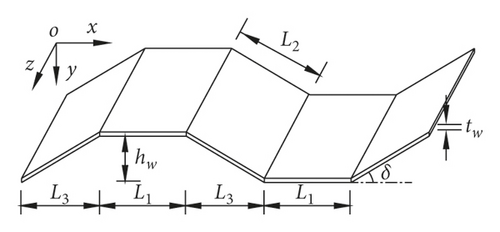
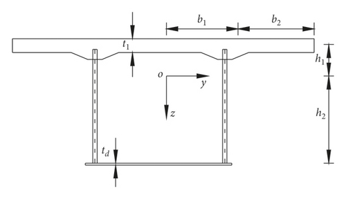
The geometric parameters of the corrugated steel webs are shown in Figure 2. Where b2 is the width of the cantilever plate, 2b1 is the width of the concrete top plate and the steel bottom plate, t1 and td are the thickness of the upper flange concrete and the steel bottom plate, respectively; h1 and h2 are the distance from the upper flange and the bottom plate to the neutral axis, respectively. The z-axis is the height direction of the composite box girder; and the y-axis is the width direction.
2.3. Formula Derivation
2.4. Boundary Conditions
3. Numerical Example
3.1. Example 1
Taking the single box and single cell simply supported composite box girder with CSWCB in document 18 as an example, the span length is 8 m, reference 18 for other dimensions and material parameters. Table 1 shows the midspan deflections of the single box and single cell simply supported composite box girder with CSWCB based on the present method and the test values provided by Ma et al. (2021). It can be seen that the calculated values are in good agreement with the test values, thus the accuracy of this method is verified.
| Working condition | Load amplitude | Measured value | Calculated value |
|---|---|---|---|
| Concentrated load | 17.6 kN | 1.705 | 1.912 |
| 35.2 kN | 3.325 | 3.824 | |
| 63.2 kN | 6.140 | 6.866 | |
| 71.2 kN | 7.405 | 7.735 | |
| Uniform load | 2.250 kN/m | 1.330 | 1.224 |
| 3.983 kN/m | 2.225 | 2.135 | |
| 5.625 kN/m | 3.185 | 3.241 | |
| 7.500 kN/m | 4.335 | 4.158 | |
3.2. Example 2
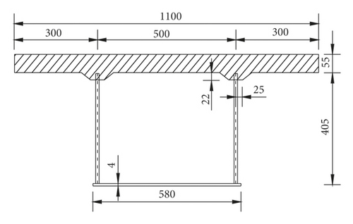
A cantilever composite box girder is designed and the span is 2.45 meters. The concrete material of the composite box girder top plate is C50, and the elastic modulus is 34.5 GPa; Q345 steel is used for corrugated steel webs and bottom plate, and the elastic modulus is 206 GPa. The cross section and steel web dimensions of the composite box girder are shown in Figure 3.

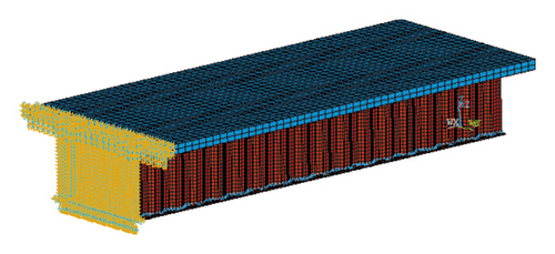
The finite element model is established by the ANSYS finite element software. The concrete top plate is simulated by SOLID65 element, the steel bottom plate and corrugated steel webs are simulated by SHELL63 element. The top and bottom plates are connected to the corrugated webs by means of the common node. All nodes of the cantilever fixed section are set as rigid constraints, and the finite element model is shown in Figure 4.
Tables 2–5 show the normal stresses distribution and fold effect of the top plate at the fixed end of the cantilever composite girder under different loads (Error in table and = (theoretical calculated value-finite element value)/finite element value ×100%; fold effect = (stress value of the composite box girder with SCWCB-stress value of composite box girder with flat steel webs)/stress value of the composite box girder with flat steel webs ×100%).
| Calculation method | Transverse coordinates of the top plate (m) | |||||||||||
|---|---|---|---|---|---|---|---|---|---|---|---|---|
| 0.00 | 0.05 | 0.10 | 0.15 | 0.20 | 0.25 | 0.30 | 0.35 | 0.40 | 0.45 | 0.50 | 0.55 | |
| Method of this paper | 1.950 | 1.976 | 2.055 | 2.185 | 2.368 | 2.603 | 2.402 | 2.240 | 2.113 | 2.023 | 1.968 | 1.951 |
| Finite element method | 1.893 | 1.957 | 1.969 | 2.096 | 2.374 | 2.612 | 2.411 | 2.178 | 2.079 | 1.962 | 1.886 | 1.893 |
| & (%) | 3.011 | 0.971 | 4.368 | 4.246 | −0.253 | −0.345 | −0.373 | 2.847 | 1.635 | 3.109 | 4.348 | 3.064 |
| Fold effect (%) | 13.22 | 14.36 | 17.25 | 20.18 | 22.45 | 26.31 | 23.71 | 21.46 | 19.96 | 18.30 | 15.74 | 14.32 |
| Calculation method | Horizontal coordinates of the bottom plate (m) | |||||
|---|---|---|---|---|---|---|
| 0.00 | 0.05 | 0.10 | 0.15 | 0.20 | 0.25 | |
| Method of this paper | −52.608 | −53.306 | −55.402 | −58.924 | −63.813 | −70.118 |
| Finite element method | −51.873 | −52.145 | −53.917 | −56.721 | −60.614 | −68.525 |
| & (%) | 1.222 | 2.226 | 2.754 | 3.884 | 5.278 | 2.325 |
| Fold effect (%) | 18.34 | 20.53 | 21.97 | 23.05 | 25.21 | 28.45 |
| Calculation method | Transverse coordinates of the top plate (m) | |||||||||||
|---|---|---|---|---|---|---|---|---|---|---|---|---|
| 0.00 | 0.05 | 0.10 | 0.15 | 0.20 | 0.25 | 0.30 | 0.35 | 0.40 | 0.45 | 0.50 | 0.55 | |
| Method of this paper | 1.370 | 1.404 | 1.521 | 1.704 | 2.005 | 2.339 | 1.972 | 1.721 | 1.537 | 1.387 | 1.303 | 1.287 |
| Finite element method | 1.405 | 1.422 | 1.497 | 1.651 | 1.892 | 2.268 | 1.915 | 1.689 | 1.561 | 1.425 | 1.364 | 1.352 |
| & (%) | −2.491 | −1.266 | 1.603 | 3.210 | 5.973 | 3.131 | 2.977 | 1.895 | −1.537 | −2.667 | −4.472 | −4.808 |
| Fold effect (%) | 6.97 | 7.02 | 7.04 | 6.95 | 7.03 | 7.05 | 7.02 | 6.97 | 6.99 | 7.03 | 7.01 | 6.98 |
| Calculation method | Horizontal coordinates of the bottom plate (m) | |||||
|---|---|---|---|---|---|---|
| 0.00 | 0.05 | 0.10 | 0.15 | 0.20 | 0.25 | |
| Method of this paper | −39.814 | −40.954 | −44.375 | −50.071 | −58.046 | −68.303 |
| Method of finite element | −37.659 | −39.241 | −42.653 | −49.035 | −56.204 | −66.316 |
| & (%) | 5.722 | 4.365 | 4.037 | 2.113 | 3.277 | 2.996 |
| Fold effect (%) | 13.82 | 13.84 | 13.96 | 14.11 | 14.24 | 14.41 |
From Tables 2–5, it can be seen that the calculation results of the method in this paper agree well with the finite element values, and the error is basically controlled at about 5%, thus verifying the accuracy of the method. The fold effect at the intersection of the web and the top and bottom plate under the concentrated load is 26.31% and 28.45%, respectively. Under uniform load, the fold effect at the intersection of the web and the top and bottom plates is about 7% and 14%, respectively. The reason for the fold effect is that after the flat steel web is replaced by the corrugated web, its longitudinal stiffness becomes smaller, and the deformation of the flange and the web is incompatible under the vertical load, resulting in additional strain at the connection between the flange and the web.
Figures 5 and 6 show the variation law of the shear lag coefficient along the longitudinal direction of the cantilever composite box girder under uniform loads and concentrated loads, respectively, and the shear lag coefficients are taken from the junction of the upper flange with the corrugated steel web (y = 0.25 m) and the centre of the top plate (y = 0.00 m). Figure 7 shows the transverse distribution curves of the shear lag coefficients of two different sections under vertical bending loads, with the maximum shear lag effect occurring at the fixed end section (x = 0.00 m) and a more serious negative shear lag effect at the section (x = 2.00 m).
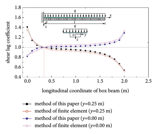
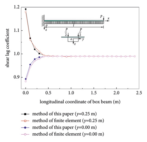
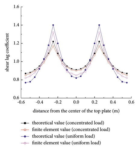
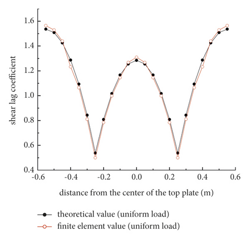
From Figures 5–7, it can be seen that the corresponding shear lag coefficients obtained from the theory and finite element method in this paper are basically consistent with the variation law along the longitudinal direction of the box girder. For cantilever composite box beams, the shear lag effect under uniform load is stronger than that under concentrated load. Under uniform load, not only shear lag effect occurs in cantilever composite box girder but also negative shear lag effect occurs at about 0.31 m away from fixed end, but no such phenomenon occurs under concentrated load. This phenomenon indicates that the load formed is one of the main factors for the negative shear lag effect of the structure, while the shear lag effect tends to be stronger with the increase of the distance from the fixed end. The shear lag effect of the section near the fixed end under the concentrated load is obvious and then decreases along the span direction.
The calculated results of the longitudinal deflection curves of cantilever composite box girders under concentrated load and uniform load are shown in Figures 8 and 9 respectively, and the comparison of the deflection of cantilever end section is shown in Table 5.
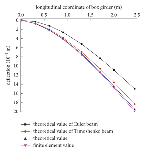
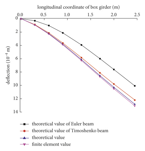
From Figures 8 and 9 and Table 6, it can be seen that the theoretical calculations in this paper agree well with the finite element values and the theoretical values of the Timoshenko girder theory, which verifies the rationality of the theoretical method. The deflection error of the theoretical calculation of the Euler beam has exceeded 9.6%. The additional deflection of shear deformation and shear lag increases from the fixed end to the cantilever end, and the additional deflection of shear deformation and shear lag of the cantilever end section under the concentrated load accounts for 22.26% and 7.82% of the primary girder deflection, respectively, indicating that shear lag and shear deformation cannot be ignored in the deflection calculation of this type of cantilever composite girder. The theoretical method in this paper can accurately calculate the longitudinal deflection curve of a cantilever composite box girder.
| Position | Concentrated load | Uniform load | ||||||||
|---|---|---|---|---|---|---|---|---|---|---|
| w/mm | f1/mm | f2/mm | (f1/w)/% | (f2/w)/% | w/mm | f1/mm | f2/mm | (f1/w)/% | (f2/w)/% | |
| Section of the cantilever end | 1.496 | 0.333 | 0.117 | 22.26 | 7.82 | 1.007 | 0.213 | 0.064 | 21.15 | 6.36 |
- Note: w is the theoretical deflection value of Euler, f1 is the additional deflection value of shear deformation, and f2 is the additional deflection value of the shear lag.
4. Parameters Analysis
Based on the model beam in example 2, the influence of the width span ratio of the cantilever composite box girder and the bending angle of corrugated steel webs on shear lag and fold effect is analyzed by the ANSYS finite element method.
4.1. Width Span Ratio
The influence of width span ratio 2b1/l is analyzed by changing the flange width 2b1 of the cantilever corrugated web box girder. The parameter range of the wide span ratio is 0.163, 0.204, 0.245, 0.286, and 0.327. The maximum shear lag coefficient and fold effect of the fixed-end section wing under different width span ratios are compared, and the results are shown in Figure 10. Z1 and Z2 represent the maximum fold effect of the wing plate and the bottom plate under concentrated load, respectively. Z3 and Z4 represent the maximum fold effect of the wing plate and the bottom plate under uniform load, respectively. J5 and J6 represent the maximum shear lag effect of the wing plate under uniform load and concentrated load, respectively.
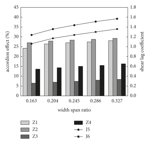
It can be seen from Figure 10 that when the width span ratio increases from 0.163 to 0.327, the maximum shear lag coefficient of the wing plate under uniform load increases from 1.24 to 1.57, and the maximum shear lag coefficient of the wing plate under concentrated load increases from 1.06 to 1.36. Therefore, the shear lag coefficient of the fixed end section of the cantilever composite box girder shows an upward trend with the increase of the width span ratio. The maximum fold effect of the wing plate under concentrated load increases from 24.19 to 28.05 and there is a positive correlation between shear lag effect and fold effect.
4.2. Corrugated Steel Web Bending Angle
Keeping the cross-sectional dimensions and span of the box girder unchanged, the corrugated steel webs were selected from three commonly used types, namely: 1600, 1200, and 1000, corresponding to corrugated angles of 30.74°, 36.53°, and 45°, respectively. Comparing the maximum shear lag coefficient and fold effect of the fixed end section flange under different corrugated angles, the results are shown in Figure 11.
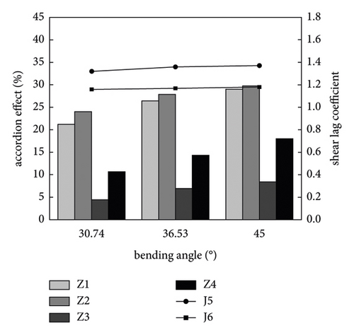
It can be seen from Figure 11 that when the bending angle increases from 30.74° to 45°, the shear lag coefficient of the fixed end section of the cantilever composite box girder shows an upward trend under the vertical load, but the amplitude is very small, and the maximum increase is 0.05, so it can be considered that the bending angle has no effect on the shear lag coefficient. Under the concentrated load, the maximum fold effect value of the wing plate of the fixed end section rises from 21.19 to 28.99, with an increase of 36.81%. Therefore, with the increase of the bending angle, the fold effect of the composite box girder is obviously enhanced.
5. Conclusion
- (1)
Based on the energy variation principle, the calculation method which can accurately calculate the deflection and stresses of the composite box girder with CSWCB is proposed by comprehensively considering shear lag, shear deformation, and fold effect.
- (2)
The fold effect generated by corrugated steel webs has a certain effect on the mechanical properties of the cantilever composite girder wings, and the effect of the fold effect is greater under concentrated loads than under uniform loads.
- (3)
The deflection error of the composite box girder with CSWCB calculated by the Euler beam theory exceeds 9.6%, and the shear deformation and shear lag additional deflection of the cantilever end section under concentrated load account for 22.26% and 7.82% of the deflection of the primary girder, respectively, indicating that shear lag and shear deformation cannot be ignored in the deflection calculation of this type of girder.
- (4)
Only a shear lag effect occurs in a cantilever composite box girder under concentrated load, while shear lag and negative shear lag effects exist simultaneously under uniform load, and the effects of both shear lag and negative shear lag tend to be stronger as the width span ratio increases.
- (5)
With the increase in the width span ratio, the effects of shear lag and fold effect of the composite box girder show a consistent increase. With the increase of the bending angle, the fold effect of the composite box girder with CSWCB is obviously enhanced, but the change in the bending angle has a negligible effect on the shear lag effect.
Conflicts of Interest
The authors declare that there are no conflicts of interest.
Acknowledgments
Science and Technology Plan of Gansu Province of China (19ZD2GA002).
Open Research
Data Availability
The data generated or used during the study are included within the article.


