Fully Mechanized Mining Technology and Practice of Water Conservation with Large Gravity Filling of Aeolian Sand-Like Paste
Abstract
Aiming at the serious problem of Salawusu formation aquifer damage caused by caving mining in Yuyang coal mine, the technique of mechanized backfill mining with Aeolian sand-like paste was invented. Aeolian sand was used as aggregate and alkali-activated fly ash as cementing agent in the backfill material. Slurry ratio was studied where the water-sand ratio was 1 : 1.3 and the mass concentration was 72%, while slurry initial fluidity could reach 210 m. The author proposed the local resistance loss calculation method of slurry pipeline transportation, and the field gravity transport test results showed that resistance loss of unit length elbow was 4.26 times as big as loss of resistance along path; thus the pipeline diameter with 14.9 gravity of self-flowing was determined, and the pipeline flow design precision was improved by more than 10%. The backfill capacity could reach 360 m3/h and the running energy consumption was lower because of adopting backfill station model with double pulping system and underground equipment pool. The author also put forward whole backfill space sealing in which cloth consumption was only 40% of bag backfill. Industrial test showed that the backfill mining technique met requirements of water resources protection, primarily because the filling rate was 98.5% in goaf, strata behavior appeared slightly, roof water leaching was less than 2 m3/d, and surface subsidence value was only 38 mm. There were great breakthroughs in cost and production efficiency in this technology compared with similar technologies.
1. Introduction
Yuyang coal mine of Shaanxi Zhongneng Coalfield Co., Ltd. is one of the large-scale mines in Yuheng Mining Area (north area) of Jurassic Coalfield in Northwest China, with an annual output of 3 million tons. The coal seam occurrence and mining conditions are superior. The main mining 3# coal is 3.0∼3.6 m thick, with an average inclination of 1° and a buried depth of 190∼230 m. The mine is located in the southern margin of Maowusu Desert, belonging to arid and semiarid climate area, with poor water resources and fragile ecological environment. The coal seam is covered with about 40 m thick water bearing Aeolian sand layer, especially the relatively stable sand gravel aquifer of Salawusu formation at the bottom of 5∼25 m, which directly covers the outcrop of coal measure strata. The water-conducting fault zone of caving mining is easy to communicate with the aquifer above the work face, which poses a great threat to the safe mining of coal seam and the fragile ecological environment of Mu Us Desert.
Compared with strip mining, thickness limiting mining, and other water conservation mining methods [1, 2] that reduce the degree of overburden damage at the cost of reducing resource recovery, the backfill mining achieves the effect of controlling mining damage without losing coal resources by backfilling solid or cemented filling materials to the goaf, which is an ideal environment-friendly mining method. In recent years, the backfill mining technology with waste gangue and power plant fly ash as the main filling materials has been rapidly developed and applied in coal mining under buildings (structures) and near water in mining areas in central and eastern China [3–12], which has achieved remarkable economic and environmental benefits and had a demonstration effect. In view of the urgent demand of water conservation mining in Northwest Mining Area and the characteristics of extensive occurrence of aeolian sand on the surface, it is imperative to use local materials and use Aeolian sand as filling material to carry out filling mining. Yan et al. put forward a roadway pillar top coal caving filling mining method [13]; Cui et al. tested the basic properties of Aeolian sand and the properties of cemented filling materials with aeolian sand as aggregate [14]; Cao et al. used the orthogonal test to study the slump and compressive strength in 7 d and 28 d for paste filling materials with Aeolian sand; and the optimal proportion of filling materials was analyzed by SEM [15]. The above results promoted the development of Aeolian sand filling mining technology; however, the slurry preparation, transportation system, and filling coal mining technology suitable for the characteristics of Aeolian sand filling materials have not been formed, and the engineering practice is lacking. In addition, the benefits of filling coal mining are related to the popularization and application value of this technology. It is of great significance to improve the filling mining production capacity and reduce the cost from the perspective of materials, systems, and processes.
After three years, the author and his team have developed high fluidity Aeolian sand-like paste filling materials, established a 14.9-large line artesian flow system, adopted the mode of double pulping system and low energy consumption filling station, put forward a new way of overall sealing of the filling space of the working face, and formed a relatively perfect high-efficiency and low-cost Aeolian sand-like paste filling coal mining technology. The successful trial mining has been carried out in no. 2307 fully mechanized mining filling face of Yuyang coal mine, which meets the requirements of protecting the overlying aquifer and provides a reference for promoting the application of filling and water conservation mining technology in Northwest Mining Area.
2. Overview of Test Mine and Working Face
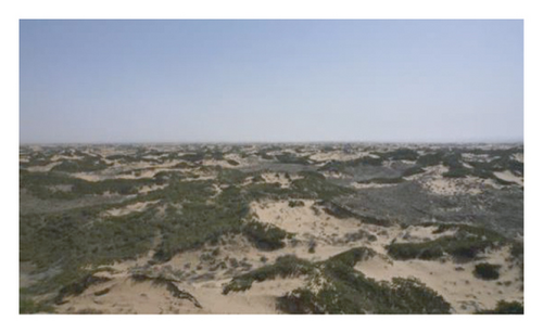
The mine field area of Yuyang coal mine is 13.0 km2. The surface is desert beach and semifixed dune landform, with little topographic fluctuation, as shown in Figure 1. The average thickness of Cenozoic Aeolian sand layer in the mine field is about 43 m, which is composed of pore phreatic water of Salawusu formation of Upper Pleistocene and pore fissure phreatic water aquifer of Lishi loess of Middle Pleistocene. The pumping data during mine exploration and the production practice of adjacent mines show that the pore aquifer of Salawusu formation is composed of medium and coarse sand, with high sand content and pure texture, unit water inflow q = 1.375∼2.596 L/s.m, and permeability coefficient k = 14.234∼27.463 m/d, belonging to medium ∼ strong aquifer, which is an important barrier for desert ecological environment protection. Under this aquifer, a water resisting layer composed of loess of Lishi formation of Quaternary Middle Pleistocene and laterite of Baode jingle formation of Neogene Pliocene is developed. Bedrock aquifers mainly include bedrock weathered zone aquifers and coal measure sandstone aquifers, of which the roof sandstone and medium sandstone aquifers overlying the coal seam belong to weak water bearing sandstone fissure aquifers. Under the condition of traditional high-strength caving mining, the overburden aquiclude is easy to be damaged, the pore phreatic water of Salawusu formation leaks, and the water inflow of the working face has reached 790 m3/h.
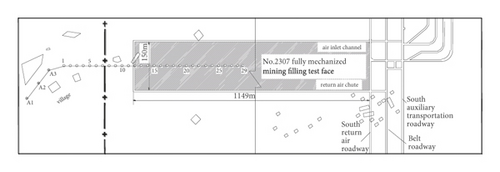
No. 2307 fully mechanized mining filling test face is located in the southwest of the mine, untapped area in the south, boundary coal pillar in the west, and return air roadway in the south in the east. The strike of the working face is 1149 m long and 150 m wide (excluding two lanes), the average mining thickness is 3.5 m, and the dip angle is 0.28°. The coal seam floor elevation is +966∼+971m, the ground elevation is +1160∼+1169m, and the buried depth is 190∼198 m.There are scattered houses on the surface. In order to monitor the surface movement and deformation, one strike observation line is set above the cut hole, including 3 control points, A1, A2, and A3, with spacing of 50 m. There are 29 observation points: 1#∼29#, the point spacing is 20 m, and the total length of the survey line is 690 m, as shown in Figure 2, which meets the observation requirements of mining impact. Observation shall be carried out once a month from the mining of the working face.
3. Characteristics of Aeolian Sand-Like Paste Filling Material
3.1. Filling Material Composition
3.1.1. Aeolian Sand
32 sand samples were collected from Aeolian sand layers at different positions on the surface of Yuyang coal mine. Through microscopic observation (Figure 3), the main mineral components are quartz, feldspar, mica, and so forth. X-ray diffraction analysis shows that the chemical components are SiO2, Al2O3, Cao, Fe2O3, and MgO, and the main components SiO2 and Al2O3 account for 65.75% and 12.83%, respectively. The screening test shows that the particle size of Aeolian sand is mostly concentrated between 0.075 and 0.6 mm, with an average of 0.249 mm and a maximum of no more than 1.0 mm. It belongs to ultrafine sand, with nonuniformity coefficient Cu = 2.49 and curvature coefficient CC = 1.03. The bulk density is 1.503∼1.543 g/cm3, and the porosity is 40.2%∼42.5%. The apparent density is 2.571∼2.599 g/cm3 [16, 17].
3.1.2. Cementitious Material
Alkali-activated cementitious material is a new type of inorganic nonmetallic cementitious material developed in recent years. It takes pozzolanic or potential hydraulic active materials (e.g., slag, fly ash, etc.) as the main material, which is activated by adding alkaline activator to produce hydraulic cementitious performance. Making full use of industrial waste, this material has low cost, and its strength, acid and alkali resistance, and carbonation resistance are better than those of Portland cement [18]. The filling material is a cementitious material with fly ash as the main material and lime, gypsum, and cement as alkaline activator.
The fly ash is grade III fly ash from Guohua Jinjie Power Plant. Its main components are SiO2, Al2O3, Fe2O3, FeO, Cao, and TiO2, with an average apparent density of 2.18 g·cm−3. Calcium quicklime is used as quicklime, with reference to the standard of building quicklime (JC/T479-1992). Gypsum shall meet the requirements of reference building materials and grade 1.6 specified in GB9776-2008. The cement is 32.5# ordinary Portland cement.
3.1.3. Water
Mine water can be used to prepare filling materials.
3.2. Filling Material Ratio Experiment
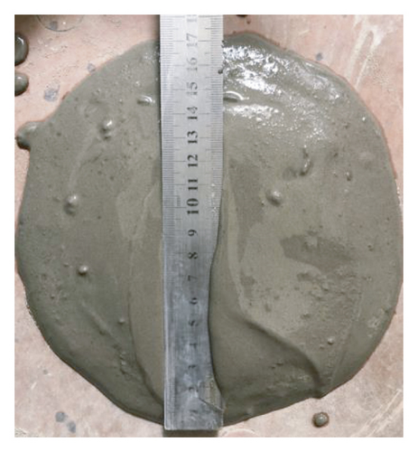
The rheological parameters (fluidity, viscosity, and yield stress) of filling slurry, final setting time, bleeding rate, and strength of filling body are the main performance indexes of cemented filling material. The orthogonal test method of two factors and four levels is used to test the performance of filling materials with different ratios. The mass concentrations are 69%, 72%, and 75%, and the water-sand ratios are 1 : 0.7, 1 : 1, and 1 : 1.3. The experimental results are shown in Table 1. The measurement of slurry fluidity is shown in Figure 3.
| Number | Concentration/% | Water-sand ratio | Viscosity coefficient/(Pa·s) | Yield stress/Pa | Initial mobility/mm | Final setting time/h | Bleeding rate/% | Strength at different ages/MPa | |||
|---|---|---|---|---|---|---|---|---|---|---|---|
| 12 h | 3 d | 7 d | 28 d | ||||||||
| 1 | 69 | 1 : 0.7 | 0.096 | 2.31 | 266 | 6.2 | 0.9 | 0.21 | 2.15 | 3.30 | 4.92 |
| 2 | 72 | 1 : 1 | 0.256 | 4.85 | 206 | 6.2 | 1.0 | 0.19 | 2.20 | 3.31 | 4.77 |
| 3 | 75 | 1 : 1.3 | 0.848 | 8.78 | 190 | 5.8 | 1.3 | 0.25 | 2.56 | 3.44 | 5.02 |
| 4 | 69 | 1 : 1 | 0.110 | 2.43 | 247 | 6.5 | 1.2 | 0.19 | 1.98 | 3.12 | 4.67 |
| 5 | 72 | 1 : 1.3 | 0.261 | 5.04 | 210 | 6.0 | 1.2 | 0.20 | 2.11 | 3.23 | 4.80 |
| 6 | 69 | 1 : 1.3 | 0.124 | 2.61 | 240 | 6.3 | 1.5 | 0.18 | 1.92 | 3.02 | 4.55 |
| 7 | 75 | 1 : 0.7 | 0.243 | 4.52 | 208 | 6.0 | 0.5 | 0.24 | 2.41 | 3.53 | 4.98 |
| 8 | 72 | 1 : 0.7 | 0.238 | 4.37 | 214 | 6.1 | 0.6 | 0.17 | 2.26 | 3.34 | 4.87 |
| 9 | 75 | 1 : 1 | 0.264 | 4.96 | 193 | 6.1 | 0.8 | 0.21 | 2.32 | 3.48 | 4.90 |
Compared with the current mine cemented filling materials [19–21], the Aeolian sand-like paste filling materials show the characteristics of strong fluidity and high strength as a whole. From the perspective of meeting the performance indexes and making full use of Aeolian sand as much as possible, the scheme with water-sand ratio of 1 : 1.3 and mass concentration of 72% is finally selected.
4. Feasibility Analysis and Determination of Inner Diameter of Pipeline for Gravity Transportation of Large Pipeline
4.1. Analysis of Local Resistance Loss in Slurry Pipeline Transportation
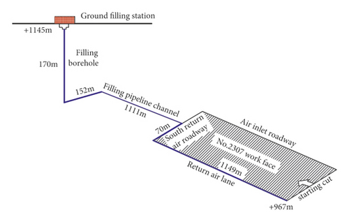
The filling station of Yuyang coal mine is located in the industrial square. The slurry conveying pipeline reaches the farthest cutting position along the vertical drilling, filling pipeline channel, south return air roadway, and no. 2307 work face return air roadway. The length L = 2652 m, the height difference between the starting point and the end point h = 178 m (Figure 4), and the filling multiple line is n = L/h = 14.9, which has exceeded the maximum gravity multiple line of the current mine by 11.76 [22]. There are two kinds of filling slurry transportation: pumping and self-flow. In view of the strong fluidity of Aeolian sand-like paste slurry, the feasibility of self-flow transportation mode is studied.
Equation (1) shows that if the slurry can be transported by gravity, the potential energy of the height difference between the starting point and the ending point of the pipeline should overcome its resistance loss in the process of pipeline transportation and make the outlet slurry meet certain flow requirements. It can be seen that determining the resistance loss in the conveying process is very important to analyze the feasibility of gravity conveying.
- (1)
The resistance loss is is the product of the total length Ls of the straight pipe section and the resistance loss is per unit length. is is usually calculated by the following formula:
(2) - (2)
where τ0 is the yield stress of slurry, Pa; D is the inner diameter of the pipeline, m; η is the slurry viscosity, Pa·s.
- (3)
Due to the complex flow law of slurry in the elbow section of the pipeline, the local loss of the pipeline in the literature is considered as a whole and is calculated according to 10%∼20% of the total resistance loss along the pipeline [23, 24]; that is, formula (2) is expressed as
Compared with formulas (3) and (5) including the elbow parameters of specific pipeline and the multiple relationship between the local resistance loss per unit length and the resistance loss along the way, the local resistance loss can be determined by obtaining the value of K through test.
4.2. Field Gravity Conveying Test
Theoretical analysis, numerical simulation, and loop experiment play an important role in the study of filling slurry pipeline transportation law [25, 26]. However, due to the complexity of slurry transportation process and large similarity of simulation, the results often deviate from the reality. Using the idle pipeline of the mine to carry out the slurry transportation test in the field according to the fill-times-line and length similar to the design can provide more accurate test parameters for studying the slurry transportation law.
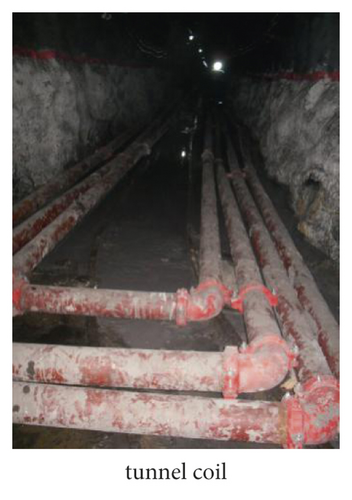
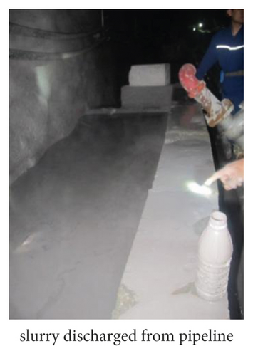
The purpose of the field artesian conveying test of Aeolian sand-like paste body is to determine the value of K, so as to provide a basis for the feasibility analysis and pipe diameter selection of 14.9 fill-times-line artesian conveying in Yuyang coal mine. The test was carried out in a mine site, and a simple pulping station was set on the ground, and the filling materials used were completely consistent with the actual filling. The transmission pipeline uses idle drainage pipe, and the model is Φ133 × 6 seamless steel pipe, with an inner diameter of 121 mm and a total length of 2480 m, which is composed of 145 m vertical pipe and 2335 m underground pipe. The filling gravity is 13.1. There was a large slope in the underground roadway, so some lines show certain fluctuation. In order to occupy the production roadway as little as possible and set more elbows, coil mode is adopted locally. There were 22 elbows (all 90°) in the pipeline.
- (1)
The Aeolian sand-like paste slurry realizes the self-flow transportation under the conditions of gradient 8.5, 10.5, and 13.1, and the flow decreases with the increase of filling gravity. The flow can reach 70.4 m3/h under the condition of gradient 13.1. It can be predicted that the 14.9 gradient self-flow transportation of Yuyang coal mine is feasible, and the flow requirements can be realized through the adjustment of pipe diameter.
- (2)
Substitute the relevant data of three conveying tests into equation (5) to obtain K1 = 4.4, K2 = 4.2, and K3 = 4.2, and the average value K = 4.3, that is, the local resistance loss of unit length elbow is 4.26 times that of straight pipe. The calculated resistance losses of straight pipe section and elbow section in the three transportation tests are shown in Table 3. The ratio of resistance loss of elbow section to straight pipe section is 4.8%, 3.9%, and 3.6%, respectively, which does not reach 10%∼20% in the traditional estimation method, indicating that the calculation of local resistance loss and total resistance loss of the latter is too large, so the kinetic energy of outlet slurry (flow rate) is low. Under the same flow requirements, the designed pipe diameter will be too large.
| Serial number | Elevation difference between starting point and ending point of pipeline (H)/m | Total length of pipeline (L)/m | Self-flow gravity (N) | Elbow of pipe | Outlet velocity (v)/(m/s) | Flow (Q)/(m3/h) | ||
|---|---|---|---|---|---|---|---|---|
| Number (n) | Mean radius of curvature (r)/m | Cumulative length (Lb)/m | ||||||
| 1 | 190 | 2480 | 13.1 | 22 | 1.0 | 35 | 1.70 | 70.4 |
| 2 | 220 | 2300 | 10.5 | 18 | 1.0 | 28 | 2.24 | 92.7 |
| 3 | 150 | 1274 | 8.5 | 9 | 1.0 | 14 | 2.85 | 118.0 |
| Serial number | Resistance loss along the whole pipeline/MPa | Resistance loss of elbow section/MPa | Ratio of local resistance loss to along path resistance loss/% | |
|---|---|---|---|---|
| This method | Traditional estimation method | |||
| 1 | 3.0 | 0.2 | 4.8 | 10∼20 |
| 2 | 3.5 | 0.2 | 3.9 | |
| 3 | 2.4 | 0.1 | 3.6 | |
4.3. Determination of Inner Diameter of Conveying Pipeline in Yuyang Coal Mine
The number of elbows (n) in the filling slurry conveying pipeline of Yuyang coal mine is 5, the radius of curvature is 1.5 m, and the cumulative length of the elbow section is Lb = n(πR)/2 = 12 m, and then the length of the straight pipe section is LS = l−lb = 2338 m. Substituting pipeline parameters and rheological parameters of Aeolian sand-like paste slurry and K = 4.26 into (5), the slurry flow rate and flow corresponding to the inner diameter of several groups of common pipelines are obtained, as shown in Table 4. According to the flow design requirements of 180 m3/h single pipeline, 16 Mn seamless steel pipe pipeline with inner diameter of 156 mm and wall thickness of 10 m is selected. After the completion of the system, the measured actual flow rate at the pipeline outlet is 2.66 m/s and the flow is 184 m3/h, with a design error of only 1.7%, meeting the production requirements. Using the traditional estimation method, the overall local resistance loss is considered as the minimum 10% of the resistance loss along the way. The inner diameter of the pipeline d = 0.16 m under the condition of flow of 180 m3/h is obtained through (3), which is substituted into (5), and, combined with the relationship between the actual flow and pipe diameter of Yuyang coal mine, the estimated flow is more than 202 m3/h, and the error rate is 12%.
| Serial number | Pipe inner diameter/m | Current speed/m/s | Flow/m3/s |
|---|---|---|---|
| 1 | 0.065 | 0.3 | 31.6 |
| 2 | 0.109 | 1.2 | 88.8 |
| 3 | 0.156 | 2.6 | 181.0 |
| 4 | 0.165 | 3.0 | 203.4 |
The pipeline transportation test and practice show that the flow design accuracy is more than 10% higher than that of the traditional estimation method because of obtaining the local resistance loss of the pipeline accurately, with the local resistance loss considering the specific length of the elbow section and obtaining the multiple relationship between the local resistance loss per unit length and the resistance loss along the way through the test.
5. Low Energy Consumption Filling Station Mode of Double Pulping System
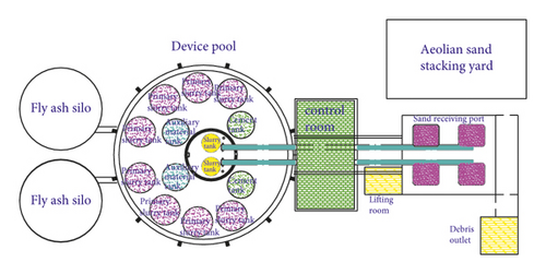
The preparation system of Aeolian sand-like paste filling slurry is composed of primary slurry tank, auxiliary material tank (storing activator), cement tank, slurry forming tank, Aeolian sand screening and conveying system, and fly ash silo. The pulping process is as follows: start the mixing motor, and inject fly ash to make the primary slurry after injecting quantitative water into the primary slurry tank; the raw materials of Aeolian sand are removed by eccentric synchronous horizontal screen (the size of screen mesh is 25 mm), and the finished sand is transported and measured by belt conveyor and electronic belt scale; the primary slurry, auxiliary materials, cement, and Aeolian sand are transported to the slurry tank according to the set proportion for uniform mixing. Automatic control is adopted for quantitative material conveying and liquid level monitoring in slurry preparation process.
The pulping capacity of filling stations at home and abroad is only 60∼150 m3/h, and a single system is often used, which has become one of the factors restricting the production capacity of backfill mining. In view of this, the filling station adopts two sets of 180 m3/h pulping systems for centralized layout and simultaneous operation. The plan is shown in Figure 6. The prepared slurry is transported to the work face through two pipelines, and the maximum filling capacity can reach 360 m3/h.
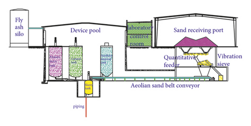
Due to the higher height of the storage tank, the process of upward water supply, ash striking, and material conveying causes great energy consumption waste and increases the operation cost. Therefore, the filling station is designed in the way of underground equipment pool, as shown in Figure 5: the primary slurry tank, auxiliary material tank, and cement tank are placed 10 m below the ground, and the top of the tank is parallel to the ground to realize horizontal ash striking; the storage, screening, and conveying system of Aeolian sand is arranged from the ground to 10 m below, and the Aeolian sand is naturally transported downward during screening; the slurry tank is placed 15 m below the ground and is in the center of the equipment pool. The slurry tank’s top is flush with the bottom of the above equipment, where the primary slurry and various materials are transported horizontally. This style can achieve obvious effect of reducing energy consumption.
6. A New Way of Overall Sealing of Filling Space in Working Face
The cemented filling coal face adopts the short step “coal mining-filling-solidification” cycle process to move forward. How to construct the filling space fast with excellent results after each cycle of coal mining is one of the ways to improve the filling efficiency. At present, the style of filling slurry into the bags sewn by high-strength fiber cloth hung behind the support is often used, which solves the problem of building a closed space in the goaf with complex geological environment. However, there are some problems, such as unsafe working environment, large number of hanging bags, and large cloth consumption.
A new way of overall sealing of filling space is put forward: after coal mining, the fiber cloth is laid along the whole area of the top and bottom plate behind the support, and the upper and lower layers of fiber cloth are squeezed by the mechanical force at the support position, so that the filling space can be mined behind. The empty area forms a confined space, as shown in Figure 7. The relevant structures and functions of the support are as follows: an operation room is set at the rear, a fixed baffle and a lifting baffle are set at the side of the goaf, the fixed baffle is integrated with the base of the hydraulic support, the lifting baffle is slidably connected with the fixed baffle, and a flexible pad is set at the top. The specific operation of the overall sealing of the filling space is as follows: starting from the cutting of the working face, lay the fiber cloth along the full length of the top plate, the cutting coal wall, and the bottom plate behind the support, and then pull the two remaining edges of the fiber cloth to the support operation room, and then raise the lifting baffle, clamp the top and bottom cloth between the lifting baffle and the top beam, and sew or seal the fiber cloth at both ends of the working face, which forms a closed space filling. The Aeolian sand-like paste slurry is filled into the rear space through the pipeline until it is full. During the solidification of the filling body, the workers continue to connect the fiber cloth between the support operations to prepare for the next cycle. When the solidification strength of the filling body meets the requirements, lower the lifting baffle, move the support forward, and take off the fiber cloth from the filling body for the next cycle of coal mining and filling operation.
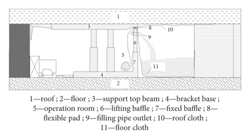
The advantages of the new method of overall sealing of the filling space are that workers work in the support operation room during the whole process, and the safety is guaranteed; the mechanical force of the support is used to realize the sealing of fiber cloth, which reduces the labor intensity of workers and improves the operation efficiency; the cloth consumption is greatly reduced, taking no. 2307 work face as an example; if bag filling is adopted, the bag size of 10 m (length) × 3 m (width) × 3.5 m (height) is considered, and 6000 bags need to be hung in the whole goaf, and the total amount of cloth is 900000 m2; the fabric consumption of this method is about 360000 m2, reducing 540000 m2, which is only 40% of that of bag hanging method.
7. Practice of Mechanized Filling Coal Mining with Aeolian Sand-Like Paste Body
7.1. Operation of Filling Coal Mining System
In October 2012, the mechanized filling and mining system of Aeolian sand-like paste body in Yuyang coal mine was completed, and the industrial test of filling and mining in no. 2307 work face was carried out at the end of November. As of middle of December 2013, the work face had been advanced 310 m in total, and 213000 t coal has been output, and the total filling slurry was about 170000 m³; 110000 tons of Aeolian sand, 83000 tons of fly ash, 12000 tons of activator, and 85000 tons of mine water were consumed. Later, due to the closure of the mine, the filling mining could not be continued.
In the early stage of the industrial test, the running in degree of the system was insufficient, the workers were not skilled in the filling process, there were many on-site implementation problems, and the production efficiency was low. In the later stage, it gradually played a high level.
7.2. Water Retaining Mining Effect
A total of 72 coal mining and filling cycles were carried out in the work face. After each cycle, the filling and roof connection should be observed and recorded along the full length of the work face. Due to the low bleeding rate of filling body and strict on-site management, the statistical results showed that the average filling rate of goaf was as high as 98.5%.
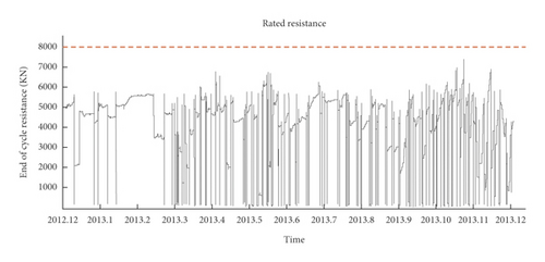
There were 88 fully mechanized mining filling supports in the work face, and one pressure measuring station was set every 10 supports. The measured data from December 11, 2012, to December 11, 2013, showed that the pressure in the middle of the working face was relatively large and gradually decreased towards the head and tail, but the roof pressure was small as a whole, the change trend was gentle with the advancement of the work face, and there was no obvious periodic pressure on the roof. The working resistance time (P-T) curve of the middle 45# support of the working face is shown in Figure 8.
The final surface subsidence curve is shown in Figure 9. The maximum subsidence is 38 mm. It is located at 22# measuring point and 196 m from the cutting hole. The buildings on surface are not affected.
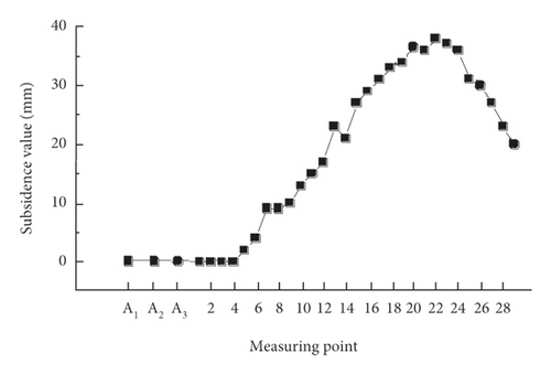
Based on the above measured data, a similar material model is established to analyze the damage degree of overlying strata in caving mining and Aeolian sand-like paste filling mining of no. 2307 work face: the “three zones” of caving mining have obvious characteristics, the height of water-conducting fault zone is 145m, running through the aquiclude, and the phreatic water of Salawusu formation is damaged; the filling mining roof did not collapse, and only a small amount of separation is generated in the lower roof, which does not damage the water resisting layer. The measured roof water leaching of the working face is less than 2 m3/d. It shows that the overburden damage of Aeolian sand-like paste filling mining is slight, and the effect of protecting water resources is realized.
7.3. Productivity and Cost
At present, the production capacity of cemented filling coal mining single face is 200000∼300000 t/a, and the filling cost per ton of coal is 110∼140 yuan, according to the author's investigation and statistics. In contrast, by adopting the large capacity filling system and the overall sealing mode of the filling space of the working face, the coal mining filling cycle with a step distance of 6.4 m is completed every two days, the monthly push progress is 88 m, and the production capacity reaches 600000 t/a, which is nearly doubled. Due to the local use of Aeolian sand and the optimization of many measures, such as simple pulping process, low energy consumption of filling station, gravity transportation, and small consumption of closed cloth at the work face, the filling cost per ton of coal is about 81.5 yuan (its composition is shown in Table 5), which is reduced by 35%.
| Filling material (including sealing cloth) | Depreciation fee of fixed assets | Operation cost of filling system | Labor cost | Other | Total |
|---|---|---|---|---|---|
| 55.2 | 8.2 | 1.2 | 7.1 | 9.8 | 81.5 |
8. Conclusion
- (1)
The developed paste-like filling material of Aeolian sand takes Aeolian sand as aggregate and alkali-activated fly ash as cementation material, which has the characteristics of strong slurry fluidity and relatively high strength of filling body. The test determines that the ratio of water to sand is 1 : 1.3 and the mass concentration is 72%.
- (2)
The calculation method of local resistance loss of slurry pipeline transportation is put forward. Through the field gravity transportation simulation test, it is concluded that the resistance loss of elbow per unit length is 4.26 times of the resistance loss along the way. The inner diameter of 14.9-fold gravity transportation pipeline is selected to improve the flow design accuracy by more than 10%.
- (3)
The low energy consumption layout mode of double pulping system in the filling station is adopted, and a new way of overall sealing the filling space of the working face is adopted, which improves the filling efficiency and reduces the cost.
- (4)
The monitoring of gob filling rate, working resistance of working face support, roof water leaching, and surface subsidence shows that the Aeolian sand-like paste backfill mining causes slight damage to the overburden, and the overlying aquifer has been effectively protected, and a great breakthrough has been made in the production efficiency and cost of this technology.
- (5)
In view of the good mechanical properties of Aeolian sand-like paste backfill and the control effect of rock stratum movement, the proportion of filling materials should be optimized and the feasibility of partial filling mining should be studied to further improve the economic benefits and promote the wider application prospect of this technology in water retaining mining in Northwest Mining Area in China.
Conflicts of Interest
The author declares no conflicts of interest.
Acknowledgments
This work was supported by the Tiandi Technology “other internal R&D projects of the company” “science and technology innovation fund” of mining design division (TDKC-2022MS-04).
Open Research
Data Availability
The data used to support the findings of this study are available from the corresponding author upon request.


