Reliable SINS/SAR/GNSS Integrated Navigation System for the Supersonic Vehicle
Abstract
In the GNSS-challenged/denied environments, compared with other aided navigation systems, synthetic aperture radar- (SAR-) aided navigation systems can achieve all-weather, all-day, and global positioning. This paper is aimed at designing a reliable navigation system for the supersonic vehicle in the whole flight phase. Considering the SAR is of great significance for the reliable and precise navigation of the supersonic vehicle, we introduce it to the terminal phase to cope with the interference of the global navigation satellite system (GNSS). At the same time, to accelerate the speed of SAR positioning, a positioning method based on the area feature and stack sequential decoding algorithm (SSDA) is designed. Then, applying the SAR positioning under the framework of the Kalman filter (KF), we propose a tightly coupled strapdown inertial navigation system (SINS)/SAR/GNSS integration algorithm, which can achieve positioning without a complicated fusion method between the front phase and terminal phase. The flight experiment results show that the proposed method can correct the average position error to 1.7 m within 1 cycle.
1. Introduction
At present, medium-range supersonic vehicle rely more on global navigation satellite system (GNSS) and inertial navigation system (INS) [1]. However, the significant problem with using GNSS technology is that the signals are very weak [2]. Taking GNSS as an example, the signals are transmitted at two L-band frequencies: L1 = 1 : 575 42 GHz and L2 = 1 : 2276 GHz from a set of orbiting satellites located at an altitude of ~20,200 Km [3]. Since the global positioning system (GPS) signals are transmitted at only ~25 W, the received signal at a typical GPS receiver is on the order of -155 to 160 dBW, which makes GNSS signals extremely susceptible to interference [4–6]. Therefore, in this case, how to design the navigation system for medium-range supersonic vehicle is vital.
To tackle the positioning problem in the GPS-denied environment, Poulose et al. proposed a novel fusion algorithm based on the traditional inertial measurement unit (IMU) and magnetometer, which firstly completes the sensor fusion algorithm for pitch and roll estimation and then completes the sensor fusion algorithm for heading estimation. Furthermore, based on an accuracy generalization benchmark for indoor localization [7], experimental results show that the proposed position-estimation algorithm achieves high position accuracy that significantly outperforms that of conventional estimation methods [8]. Gao et al. proposed a SINS/SAR loosely integrated method based on the Lupin adaptive filter, which establishes the SINS state equation as a linear model and uses SAR latitude, longitude, and height as the observation to establish the observation equation. Compared with the traditional adaptive Kalman filter, it can suppress the state divergence caused by the state noise and the observation noise [9]. Xiao et al. designed a switching mechanism between SINS/GPS and SINS/SAR to reduce the impact of matching errors on the combined system during the SAR image matching process [10]. In addition to using the latitude and longitude provided by SAR as the observation data, Xu et al. proposed an SINS/SAR loosely integrated method, which makes full use of the heading angle provided by the SAR scene matching and the east and north velocity as observations. It improves the integrated accuracy of SINS/SAR navigation information [11]. Jiang et al. proposed a SINS/SAR loosely integrated method, which uses the interferogram obtained by interferometric synthetic aperture radar (InSAR) to obtain three-dimensional positioning latitude and longitude. Compared with SAR, InSAR can obtain higher precision elevation and provide high-precision elevation correction for SINS [12]. Yandong et al. based on the SINS linear error model and SAR measurement of latitude and longitude designed an adaptive Kalman filter method to complete the SINS/SAR combination [13]. Similarly, Gao et al. designed an error suppression adaptive Kalman filter to complete the SINS/SAR combination [14]. In the latter, they proposed a SINS/GPS/SAR tightly integrated method, which uses SAR azimuth, elevation, GPS pseudorange, and pseudorange rate to establish a measurement model. As the author mentioned, the advantage of this method is that the GPS and SAR can calibrate each other under extreme conditions. However, when the GPS interferes, it is difficult to ensure the high accuracy of carrier positioning only using SAR azimuth and elevation angles [15]. Lu et al. designed an SINS/SAR tightly integrated method, which focused on the impact of the single-sided and double-sided distribution of control points on the INS/SAR combined accuracy [16].
- (i)
A SINS/SAR/GNSS tightly integrated navigation system architecture is proposed based on KF, which is equipped with a partial feedback update algorithm to tackle the high requirements for the convergence speed and equipped with an approximate extrapolation to solve nonequidistance and delayed measurement of SAR
- (ii)
Aiming at the problem of SAR delayed measurement, a SINS/SAR/GNSS measurement update algorithm is proposed, which can be performed in real-time in FPGA
The rest of this paper is organized as follows: in Section 2, we introduce the tightly coupled SINS/SAR/GNSS model based on the Kalman filter, which equipped with a partial feedback update algorithm to tackle the high requirements for the convergence speed and equipped with an approximate extrapolation to solve nonequidistance and delayed measurement of SAR. In Section 3, we conduct a flight experiment to verify the effectiveness of the proposed algorithm, and the position error is discussed. In Section 4, we discuss the experiment results, the proposed method, and the future work. Finally, conclusions are given in Section 5.
2. Methods
In short, the mainstream of the SINS/SAR can be divided into three parts according to the fusion algorithm. The first is taking the system model as nonlinear and then designing SINS/SAR integrated methods based on PF and its improved methods. It can be predicted that these methods are time-consuming. The second is taking the system model as linear and then designing SINS/SAR loosely integrated methods based on KF and its improved method, but only using the SAR observation longitude, latitude, height, and heading angle as measurements, which was greatly affected by the SAR matching accuracy. The third is taking the system model as linear and then designing SINS/SAR integrated methods based on KF and its improved methods, but considering the nonequidistance and delayed measurement of the actual SAR sensor, these methods did not give corresponding solutions.
Different from the existing algorithm, this paper proposes a tightly coupled SINS/SAR/GNSS integration algorithm for the navigation of the supersonic vehicle in the whole flight phase, as described in Section 2.1. The SAR positioning algorithm is described in Section 2.2. The system model and fusion algorithm are described in Section 2.3. Aiming at the problem of SAR delayed measurement, a SINS/SAR/GNSS measurement update algorithm is proposed, as described in Section 2.4.
2.1. System Architecture
As shown in Figure 1, the typical flight phase of a medium-range supersonic vehicle consists of three stages [17]. In the boost phase and the midcourse phase, the GNSS signal is valid, and the tightly coupled SINS/GNSS is used as the navigation method. When the supersonic vehicle enters into the terminal phase, the GNSS would be interfered, so the SAR-aided navigation system is introduced. Considering the relative position of the vehicles and jamming radar in the terminal phase, the satellite signals may not be completely jammed [18]; thus, a tightly coupled SINS/SAR/GNSS algorithm is proposed in the terminal phase.

In the boost phase and midcourse phase, since the GNSS is not interfered, the tightly SINS/GNSS integrated navigation system is used for navigation. Meanwhile, the high power consumption of SAR only allows limited use, so SAR will not be used in the two-phase. Then, in the terminal phase, when the GNSS is interfered, the tightly SINS/SAR/GNSS integrated navigation system is performed. And if the GNSS is interfered completely, the system degenerates to SINS/SAR.
As illustrated in Figure 2, the proposed system can be divided into four parts: SINS mechanization, system model, integration Kalman filter, and measurement processing. Considering the real-time performance of the vehicle-borne solution, we adopt the quaternion attitude update algorithm described in [19, 20] and the velocity and position update algorithm proposed in [21–23].
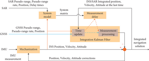
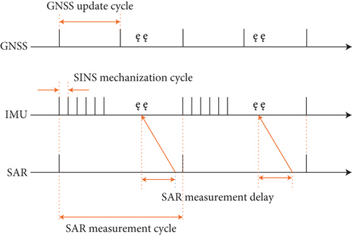
In general, the update period of SAR measurement is greater than that of GNSS and greater than that of IMU. When the single-sample algorithm is used, the update period of SINS is the same as that of IMU. Considering that the SAR measurement sequence will inevitably be nonequidistance and delayed because of the high time consuming when processing the SAR echo, which can be seen in Figure 3, an approximate extrapolation algorithm is proposed under the framework of KF. And the measurement processing is introduced in Section 2.4.
2.2. SAR Positioning by Template Match
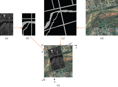
Although the measurement delay of SAR is inevitable, the shorter the matching time, the higher the accuracy of the integrated navigation system. At present, image matching is commonly conducted by feature extracting and matching, such as the ORB, SAR-SIFT, and LSD. However, all of these methods are extremely time-consuming. To tackle this, we proposed an area feature extraction and match algorithm based on the area feature and SSDA. Since SAR imaging is largely determined by the reflectivity of the echo from the ground, we utilize the pixel value to extract the scatter feature and then utilize the region growing method to generate the area feature, which is described in Figures 4(a) and 4(b). Considering that before the launch of the vehicle, the maximum position errors could be inferred based on the sensor error. Thus, the reference map is made by 1.5 times the range direction and 2.5 times the azimuth direction, respectively, of the SAR, which is described in Figure 4(c). After the area features of the real-time SAR image are extracted, we perform the SSDA (sequential similarity detection algorithm) to match it (P-uv) with the reference map (O-xy), which is described in Figure 4(e).
We conduct a comparative experiment on the mainstream feature algorithm of LSD [24], SAR-SIFT [25], ORB [26], and our method with the computer of Intel Core i5-4690K. The experiment results are shown in Table 1. Compared with other methods, our method requires fewer calculations and can achieve higher accuracy.
2.3. System Model
2.4. Kalman Filter with Feedback and Measurement Delay
After the process of correction, we set the attitude error, velocity error, and the pseudorange error to zero as the feedback. Considering the measurement delay of SAR, we utilize the approximate extrapolation algorithm to calculate the state at k frame.
Note that when the SAR measurement comes, the chi-square test is used to judge the validity of the measurement. Firstly, we calculate the innovation variance matrix by based on the saved historical data. Then, we calculate the innovation matrix by I = Zk − HkXk/k−1. The measurement is valid only when the data in the vector I is less than 3 times the diagonal data in the matrix PI.
3. Experiment and Result Discussion
To testify the effectiveness of the proposed algorithm, a flight experiment is carried out. The velocity of the vehicle in the whole flight phase is within 900-1100 m/s, and the flight time is about 160 s in the terminal phase of 120-200 Km. The experiment setup in this experiment is described in Section 3.1. The parameters of the algorithm are given in Section 3.2. The experiment results are described in Section 3.3.
3.1. Experiment Setup
The parameters of SINS, SAR, and GNSS receiver are given in Tables 2, 3, and 4, respectively. Due to the limited experimental conditions, we do not conduct GNSS jamming tests. But after analyzing the experimental data, we divided the flight phase based on the flight mileage. In the terminal phase, we select satellite data from 0 to 1 randomly as the GNSS data for the tightly coupled integrated navigation system, which can be regarded as the case of GNSS interference.
| Parameters | Unit | Value |
|---|---|---|
| Accelerometer bias | μg | 100 (1σ) |
| Accelerometer scale factor | ppm | 100 (1σ) |
| Accelerometer installation | arcsec | 20 (1σ) |
| Accelerometer white noise |
|
30 (1σ) |
| Gyroscope bias | °/h | 0.1 (1σ) |
| Gyroscope scale factor | ppm | 100 (1σ) |
| Gyroscope installation | arcsec | 20 (1σ) |
| Gyroscope white noise |
|
0.03 (1σ) |
| Update cycle | ms | 0.002 |
| Mechanization cycle | ms | 0.004 |
| Parameters | Unit | Value |
|---|---|---|
| Update cycle | s | 2 |
| Pseudorange error | m | 2 (1σ) |
| Pseudorange rate error | m/s | 0.1 (1σ) |
| Parameters | Unit | Value |
|---|---|---|
| Update cycle | ms | 100 |
| Clock correction cycle | ms | 100 |
| Pseudorange error | m | 6.5 |
| Pseudorange rate error | m/s | 0.9 |
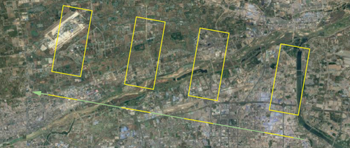
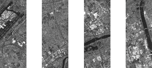
Due to the high power consumption of SAR, we perform four imaging in the terminal phase, which provides four measurement information and is described in Figure 5.
3.2. Experiment Parameters
The setting of the initial value of the state covariance matrix P, the value of the process noise covariance matrix Q, and the value of the measurement noise covariance matrix R play an important role in the convergence and convergence speed of the filter.
Furthermore, both Q and R are set to constant values. The component noise covariance corresponding to the attitude and velocity in the Q is set to the noise of the gyro and accelerometer separately, and the rest are small values. The component noise covariance corresponding to the pseudorange of the R matrix is set to 1, and the component corresponding to the pseudorange rate is set to 0.1.
3.3. Results
The experiment results of longitude error, latitude error, and altitude error are given in Figures 6, 7, and 8, respectively. At 42 s, the GNSS signals began to be jammed. Thus, in the time range of [0, 41.9] s and [42.0, 50.0] s, we perform the tightly coupled SINS/GNSS and tightly coupled SINS/SAR/GNSS integration algorithm, respectively.


As shown above, when the GNSS signal is interfered, the SINS/GNSS will cause an average position error of 2.8 m within 2 seconds, which is intolerable for supersonic vehicles in the terminal phase. At the moment of 43.9 s, 45.9 s, 47.9 s, and 49.9 s, the SINS/SAR/GNSS algorithm is utilized, and the average position error could be corrected to 1.7 m within 1 cycle. With the relatively few measurement times and the long measurement cycle, the measurement of SAR can suppress the divergence of SINS/GNSS positioning, and the proposed algorithm can achieve high positioning accuracy, which meets the requirements of supersonic vehicles.
4. Discussion
4.1. Discussion of the Experiment Results
The longitude and latitude error is shown in Figures 7 and 8, separately. Due to the different initial values, we only show the details of the SINS/SAR/GNSS error without drawing the details of the SINS/GNSS error in the subfigure. However, it can be clearly seen from the comparison curve in the range of [42.0, 50.0] s that the SAR measurement plays an important role in correcting the positioning of the navigation system when the GNSS is interfered. At the moment of 43.9 s, 45.9 s, 47.9 s, and 49.9 s, when the SAR measurement comes, the SINS/SAR/GNSS algorithm is utilized, and the average position error could be corrected to 1.7 m within 1 cycle.
As for the tightly SINS/SAR/GNSS integrated navigation system, there are few descriptions in the current published literature. At the same time, due to the uncertain delay of SAR measurement, few literatures have been found to propose a system solution. Therefore, this paper only compares the proposed method with the classical tightly SINS/GNSS integrated method.
4.2. Discussion of the Proposed System
The purpose of the proposed system is to design a SINS/SAR/GNSS integrated navigation system for the medium-range supersonic vehicle in the whole flight phase to tackle the interference of GNSS. In the early phase of the flight process, when the GNSS signal is not interfered with, the tightly SINS/GNSS integrated navigation system is used for navigation. Considering that the vehicle flies in its own territory in the early phase, the GNSS will not be interfered. Furthermore, the high power consumption of SAR only allows limited use, so SAR will not be used in this phase. In the terminal phase when the GNSS signal has interfered, the tightly SINS/SAR/GNSS integrated navigation system is performed.
To cope with the SAR measurement delay, we design an approximate extrapolation algorithm under the framework of Kalman filter. This is an engineering solution, and the convergence of the method has not been proved theoretically. However, qualitative analysis can show that the approximate extrapolation algorithm has limited influence on the Kalman filter. This method will indeed bring about approximate errors which depend on the difference between the change of actual navigation information and the simulated linear change. In fact, considering that the attitude and velocity changes of the supersonic vehicle after the boost phase are small, the navigation change of the navigation state is small. Thus, the navigation state can be considered as linear, which is the basis of the application of this method. Moreover, it should be noted that this method can only be performed at discrete moments; thus, the shorter the SINS mechanization period, the higher the accuracy of the integrated navigation.
4.3. Discussion of the Future Work
According to Equation (11), when the SAR measurement fails and the GNSS is completely interfered with, the tightly SINS/SAR/GNSS integrated navigation system degenerates into a SINS navigation system. Actually, for general supersonic vehicles, after the boost phase, the velocity of the vehicle is within 900-1100 m/s, and the flight time is still about 160 s in the terminal phase of 120-200 Km. This allows sufficient time for SAR measurement, and it will generally return 4-25 effective measurements in the terminal phase, which is sufficient for the integrated system. Thus, the most important thing is the matching accuracy, which determines the positioning accuracy of the vehicle. At the same time, according to our experiments, different SAR matching rules should be designed in different environments to improve the matching accuracy, such as towns, rivers, mountains, plateaus, and other places.
Therefore, in the future, we will study SAR matching and positioning in various complex environments and, at the same time, design automatic selection rules for different matching areas and increase the matching success rate to 99%. Furthermore, we will carry out research on the matching of SAR images and satellite images based on neural networks and, at the same time, explore its deployment on the vehicle processor.
5. Conclusions
Since GNSS signals are easily interfered, this paper proposes a tightly coupled SINS/SAR/GNSS integration algorithm, which can complete the navigation of supersonic vehicles in the whole flight phase even if the GNSS signal is interfered completely. In the boost and midcourse phase, we use the tightly coupled SINS/GNSS integration as the navigation method. In the terminal phase, we introduce the SAR-aided navigation system and proposed a tightly coupled SINS/SAR/GNSS integration algorithm to cope with the interference of the GNSS. In order to accelerate the speed of SAR positioning and improve the accuracy of position at the same time, we design a positioning method based on the area feature and SSDA. The comparison experiment shows that our method possesses the highest accuracy and speed. Finally, the experiment results show that the proposed tightly coupled SINS/SAR/GNSS integration algorithm can correct the average position error to 1.7 m within 1 cycle. In short, the proposed SINS/SAR/GNSS algorithm can complete the navigation in the whole phase and suppress the divergence in terminal phase compared with conventional SINS/GNSS.
Conflicts of Interest
The authors declare no conflict of interest.
Acknowledgments
This work was supported by the National Defense Fundamental Scientific Research of the Central Military Commission (CMC) under grant 2019-JCJQ-2D-078.
Open Research
Data Availability
The data supporting the findings of this study are available within the paper. The raw data of SINS, SAR, image, and GNSS can be obtained through email with the permission of the authors.


