Mechanism of Extruding Flowing Floor Heave in Mining Gateways Using an Elastic Foundation Beam Model
Abstract
Considering the action of high bearing pressures, a mechanical model of a coal wall mining gateway is established based on the elastic theory. The stress-strain distribution of the coal body is also discussed. According to the compression column model, under the action of the peak-bearing pressure, the maximum horizontal tensile strain in the coal wall is located at 0.65 times the height of the roadway. Furthermore, a theoretical formula for the limit equilibrium zone width and the ultimate tensile strain of the coal body was proposed. The results show that the width of the limit equilibrium zone of the coal wall is related to the ultimate tensile strain of the coal body, the maximum bearing pressure, Poisson’s ratio, the elastic modulus, the original rock stress, and the width of the elastic zone. The maximum shearing breakage depth and position of the floor rock under the plastic flow extruded through coal walls are discussed. Finally, taking the 350–450 m section of the transportation lane in the 14501 working face of Bailiang coal mine as an example, the limit equilibrium of the wall width and the floor breakage depth are calculated on the basis of the relevant parameters. Based on the results, bolt support parameters are designed, which enhance the stability of surrounding rock significantly, providing a theoretical reference for the prevention of liquid gateway floor heave.
1. Introduction
Floor heave is becoming increasingly common with the sustained increases in the scale and depth of underground excavation, which is a technical issue that needs urgent addressing. A significant number of on-site analyses on floor heave have been carried out over the past few years. The floor heave in railways induced by soil swelling has been investigated in several countries. Currently, many methods have been developed to measure the soil swelling pressure and swelling potential through experimentation (Al-Basma et al. [1]; Al-Mhaidib [2]; Al-Shamrani and Dhowian [3]). In addition, with increases in the mining depth and intensity of coal mines, along with more complex geological conditions, a large number of floor heave have appeared in the underground tunnels of coal mines, tectonic stress, mining induced stress, water, elastic deformation, and broken soft surrounding rock may lead to roadway floor heave, which have become an important factor restricting the safe and efficient operation of coal mines (Kang and Hu [4]; Ma and Chong-Jiaong [5]; Jiang and Lu [6]; He [7]; Wang and Chong-Jiong [8]).
In recent years, engineering experts have attempted to study the mechanism and control measures for underground engineering heave. Anh-Minh et al. [9] studied the mechanism of floor heave in a railway tunnel in southern France and found that they were caused by soil expansion. To discuss the effect of grooving methods to suppress the floor heave, Jin and Lian-Guo [10] used finite-difference software to numerically simulate floor grooving, finding that selecting appropriate grooving parameters can improve the control effect of soft rock tunnel floor heave. Tang et al. [11] believed that floor heave was largely caused by degradation in the strength of the floor in contact with water and proposed a model to simulate the process of the floor heave in which the tunnel floor swells with water. Wang et al. [12] observed three types of floor heave: intumescent floor heave, extrusion and mobility floor heave, and compound floor heave in double-track transportation roadways in the west wing of Tingnan Coal Mine. Chang et al. [13] compared the anchoring mechanism of resin bolts and hydraulic expansion bolts, analyzing the application of hydraulic expansion bolts in controlling floor heave in soft rock roadways. Yongshui et al. [14] proposed a new type of combined reinforcement and support system for the floor of underground tunnels in coal mines. Sun et al. [15] used a finite-difference method to analyze the failure mechanism and coupling control countermeasures of asymmetric floor heave in deep rock roadway. Fu-Rong et al. [16] built an integral mechanical model that combined semicircular arches and straight walls to solve the problems of floor heave in deep collieries. Xi-Gui et al. [17] studied the evolution law of the stress slip line field, ultimate load, and velocity, discussing the mechanism of and countermeasures against the kick-dumping of the fold entry of the smooth layer in the Datun mining area. Qiang and Xiang et al. [18] established a mechanical analysis model of roadway floors, obtaining analytical solutions for the stress and displacement of roadway floors. Zhao et al. [19] proposed a closed support method using inverted U-shaped steel arches on the floors of roadways to improve the support effect of the floor and prevent floor heave. Xu et al. [20] proposed the bolt method and steel pile method to control floor heave by actually using a floor heave law for gob-side entry retention.
The aforementioned studies have played active roles in effectively controlling floor heave. Owing to the high complexity of the lithology and stress state, there is still a lack of a unified understanding of the mechanism of roadway floor heave, resulting in ineffective control measures. In general, the treatment effect of the floor heave is not ideal. In fact, for gateway floors, the coal mass of the two sides plays a role in the transfer stress; therefore, the occurrence and development floor heave is closely related to the distribution of the support pressure on the two sides.
Consequently, this study firstly studies the load distribution law and the associated limit equilibrium zone width of the coal wall in the extraction opening under the support pressure using elastic foundation beam theory. Based on this, the deformation and destruction law of the floor under the extrusion of the coal wall is discussed.
2. Analysis of the Stress and Deformation of the Coal Body at the Side of the Roadway
2.1. Establishment of the Mechanical Analysis Model of the Coal Gang
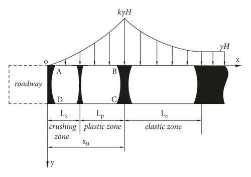
Usually, support pressure is formed on the sides of roadways. In this study, the coal sidewall on both sides of the roadway is called coal gang. If there is no support, under the action of the vertical support pressure, the coal gang will manifest a crushing zone, plastic zone, and elastic zone, as shown in Figure 1 [21], in which k is the stress concentration factor.
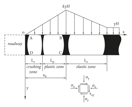
To facilitate a discussion, the support pressure above the coal gang in the roadway is simplified as a linear distribution, as shown in Figure 2, k is the stress concentration factor.
2.2. Deformation Calculation Principle of Coal Gang Rock Masses
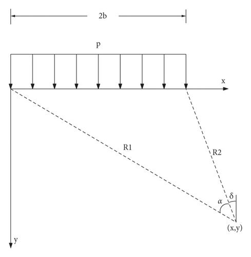
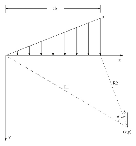
Although rock masses at the sides of roadways are discontinuous, heterogeneous, and anisotropic in terms of their physical and mechanical properties, their deformation range caused by excavation and unloading is usually small, and a linear distribution can basically reflect the coal-side characteristics. For the objective distribution law of the bearing pressure, it is advisable to set the rock mass at the side of the roadway to be continuous, homogeneous, and isotropic, and the bearing pressure is then superimposed according to the two working conditions of uniform load and linear load. In a certain range of the coal gang, a single unit is selected as the research object. According to the analysis principle of each stress component of a semi-infinite body under normal load, the stress components σx, σy, and τxy, generated by the unit body under the action of each partial load, can be calculated; then, the stress components can be superimposed on these to obtain the coal stress components at any point in the band [22, 23]. The force model at any point in the coal bank of the roadway under the action of uniform distributed load and linear distributed load is established, as shown in Figures 3 and 4, respectively.
2.3. Determination of the Stress Components of Coal Gang Rock Masses
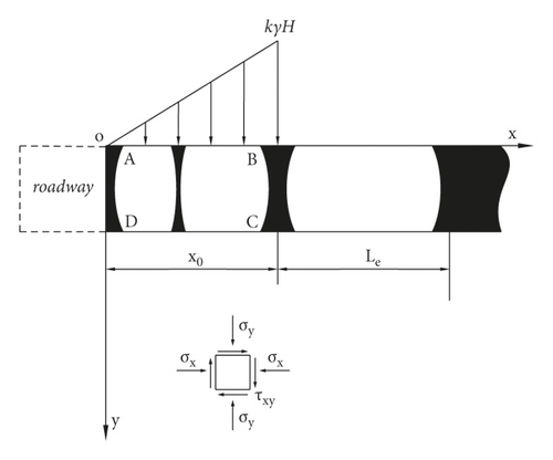
All variables in (1) to (6) are represented by the rectangular coordinate values x and y. Let the peak stress P1 = kγH and P0 = γH, according to the load distribution form, and divide the simplified model of the roadway coal gang bearing pressure shown in Figure 2 into three parts; the stress components of each part can be calculated as follows.
2.3.1. Linear Loads in the Limit Equilibrium Area
The linear load calculation model of the limit equilibrium zone of the coal gang is shown in Figure 5.
2.3.2. Uniform Load Distribution in the Elastic Zone
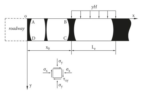
The calculation model of the uniform load in the elastic zone of the coal gang is shown in Figure 6.
2.3.3. Linear Load in the Elastic Zone
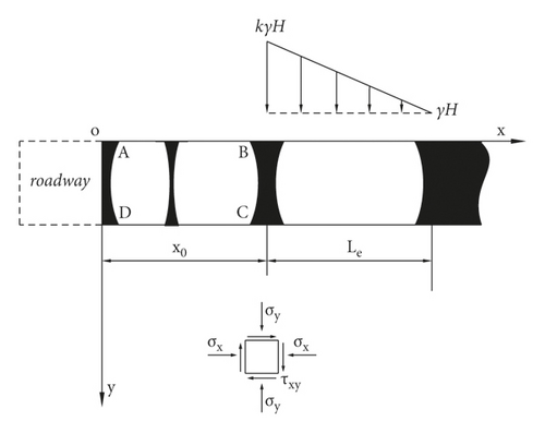
The calculation model for the linear load in the elastic zone of the coal gang is shown in Figure 7.
2.4. Stress-Strain Analysis of the Coal-Bearing Rock Mass
3. Width Analysis of the Limit Equilibrium Zone of Roadway Coal Gang
3.1. Establishment of a Pillar Model for the Coal Gang Rock Mass under Bearing Pressure
In engineering practice, after a roadway is excavated, the coal-bearing rock mass will expand and deform into the roadway under the action of a large vertical support pressure, which will lead to radial tensile strain in the coal-bearing rock mass towards the roadway. The bearing pressure increases continuously. For the coal gang rock mass on a specific interface, its deformation failure under the bearing pressure has obvious “compression column” deflection characteristics, as shown in Figure 8.
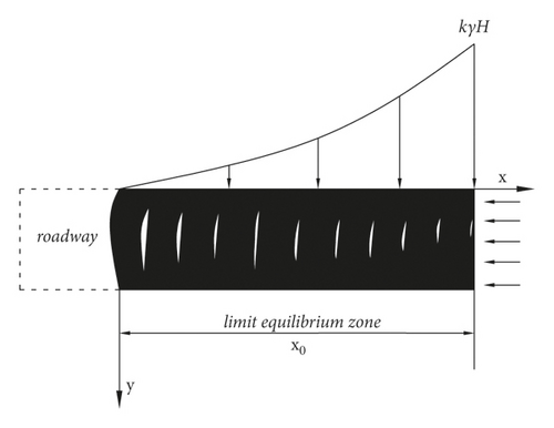
When the radial tensile strain of the rock mass at the elastic-plastic interface of the coal gang reaches its ultimate tensile strain under the action of the support pressure above it, the “compressed column” rock mass on the interface will be in a critical state of flexural fracture. Owing to the continuous distribution of the bearing pressure above the coal gang, on the different interfaces from the elastic-plastic interface to the coal gang surface, the flexural deformation of the “compression column” rock mass gradually increases, and multiple “compression columns” are juxtaposed. The radial deflection and deformation of the rock mass are continuously superimposed and produce a “bump” on the surface of the coal gang, finally forming a continuous limit equilibrium zone within a certain depth of the coal gang [24, 25].
3.2. Flexural Fracture Mechanics Analysis of the Coal Gang Rock Mass
Taking the elastoplastic interface rock mass of the coal gang as the research object and ignoring the weight of the interface rock mass itself and its compressive deformation in the vertical direction, the “compression column” model of the elastoplastic interface rock mass under bearing pressure is established, as shown in Figure 9.
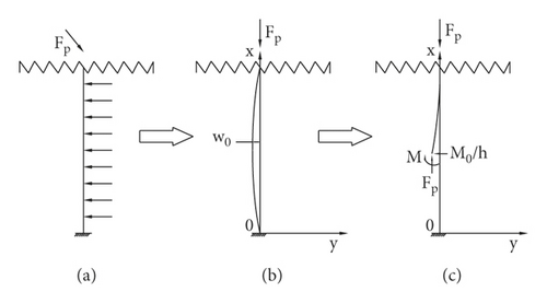
Equation (29) shows that the horizontal deflection deformation curve of the “compression column” rock mass on the elastic-plastic interface of the coal gang under the action of the bearing pressure is a half-sine wave, and the maximum horizontal deflection displacement is located at 0.65h from the bottom plate. When the horizontal tensile strain of the rock mass at this point reaches its ultimate tensile strain, the “compressed column” rock mass will enter the critical state of flexural fracture, which is consistent with the results found in previous studies [27–29].
3.3. Calculation of the Width of the Limit Equilibrium Zone of Coal Gang
It can be seen from (35) that the width of the limit equilibrium zone of the coal gang in the roadway is an implicit function of the ultimate tensile strain of the coal gang rock mass. Furthermore, it is closely related to the original rock stress, the peak stress level of redistribution after roadway excavation, and the width of the elastic zone of the coal gang.
4. Analysis of the Deformation and Failure of Floor Rock Masses in Gateways
4.1. Basic Deformation and Failure Process of the Floor Rock Mass
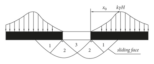
Figure 10 shows the plastic failure zoning of the floor. The limit equilibrium zone with a certain width of the coal wall exists after gateway excavation. The floor rock within the limit equilibrium zone will be cut off and is out of touch with the rock mass at the bottom corner of the wall when the support pressure reaches or exceeds the limit strength of the active zone rock mass (first zone) of the gateway floor. The rock mass in the active zone is compressed in the vertical direction, whose deformation and failure will occur and enter a broken zone; simultaneously, the rock mass of the active zone will expand in the horizontal direction and squeeze the rock mass in the transition zone (second zone). In addition, the rock mass of the transition zone continues to squeeze the rock mass of the passive zone (third zone). A continuous shear slip surface is gradually formed at the floor in the transition zone and the passive zone. Finally, the floor rock of the passive zone lifts up, leading to floor heave at a different scale [30, 31].
4.2. Maximum Damage Depth of the Floor Rock Mass
The rock mass of the floor is simplified as a medium with elastoplastic characteristics, whose slide line field on support pressure is illustrated in Figure 11.
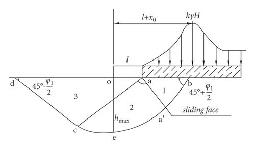
To facilitate simpler analysis and calculation, the mechanical calculation model of the floor failure depth is shown in Figure 12.
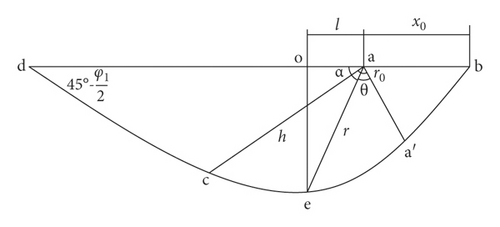
An analysis of (43) and (47) shows that the maximum shearing breakage depth of the floor and its distance to the surface of the corresponding coal wall depends on the limit equilibrium zone width of the coal wall and the internal friction angle of the floor rock mass.
5. Engineering Case Analysis
5.1. Engineering Description
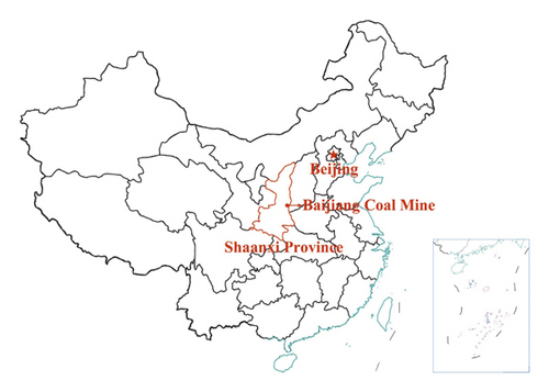
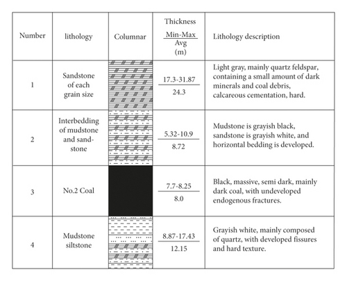
The Shaanxi Chenghe Bailiang Coal Mine (the geographical location is shown in Figure 13) No. 4 main coal seam 14501 working face transportation trough was designed as a rectangular section with dimensions of 4000 × 4600 mm, with an average burial depth of 600 m, the roof and floor slate properties of the roadway are shown in Figure 14. Although the surrounding rock of the roadway was supported by high-strength bolts (cables) in the early stages of excavation, severe deformation of the sidewall and floor still occurred, and the convergence rate of the two groups was as high as 40–45 mm/d, which seriously affected the later stages of operation. The recovery work is carried out normally.
5.2. Theoretical Analysis
5.2.1. Width Analysis of the Limit Equilibrium Zone of Coal Gang
After on-site testing and engineering analysis, the parameters of the rock mass in the 14501 working face of Bailiang Mine are listed in Table 1.
| Parameters | H (m) | γ (kN·m−3) | Ks (GPa/m) | c0 (MPa) | φ0 (°) | λ | k | E (GPa) | μ | εtmax (×10−3) |
|---|---|---|---|---|---|---|---|---|---|---|
| Value | 600 | 25 | 0.14 | 3.0 | 27 | 0.75 | 1.5 | 3.4 | 0.15 | 0.35 |
From (55), it can be seen that the width of the limit equilibrium zone of the 350–450 m section of the 14501 transport trough is x0 = 3.2 m.
5.2.2. Maximum Damage Depth of the Floor
5.3. Field Measurement
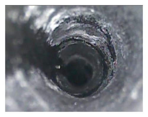
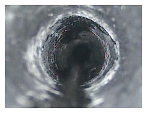
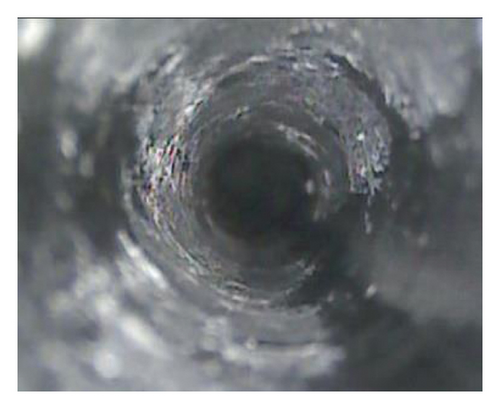
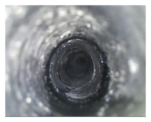
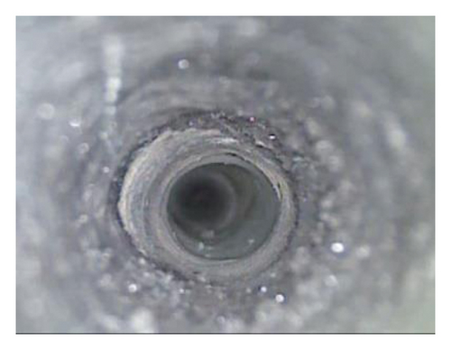
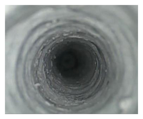
To compare the theoretical calculation result and engineering practice, the borehole peep instrument is used to peep the borehole within 8m of the roadway floor on floor. Figure 15 illustrates the deformation and failure of the floor rock mass at different depths. It can be clearly seen that the crack developed most from 3.5 m to 4.0 m, indicating that the theoretical calculation results of (56) and (57) verify the damage depth.
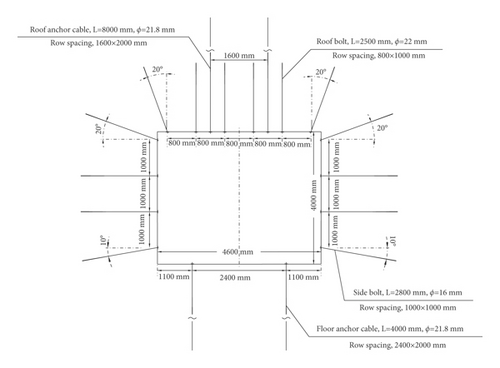
On the basis of determining the limit equilibrium zone of the coal wall and the maximum damage depth of the floor, the support parameters of the prestressed bolt and anchor wire were designed rationally, and a supporting scheme was implemented, as shown in Figure 16. The results show that the stability of the coal wall and floor has been improved greatly.
6. Conclusions
This study investigates the mechanism of extruding flowing floor heave in mining gateways. Treating the coal body on the elastic-plastic interface as a cylinder model under bearing pressure, the equations of the limit equilibrium zone width of the coal wall and the maximum damage depth of the floor are formulated. The main conclusions of this study are as follows. (1) The width of the limit equilibrium zone of the coal wall depends on the ultimate tensile strain of the coal body, the maximum bearing pressure, Poisson’s ratio, the elastic modulus, the original rock stress, and the elastic zone width. (2) The deformation and failure law of the floor rock under the extrusion of the coal wall confirms to the slip line field theory. The maximum shearing breakage depth of the floor has a linear relation with the limit equilibrium zone width. (3) The maximum shearing breakage depth of the floor and its distance to the surface of the corresponding coal wall depends on the limit equilibrium zone width of the coal wall and the internal friction angle of the floor rock mass. (4) Experimentally measured data have been used to validate the theoretical value of the breakage depth of the floor. As a result, the elastic foundation beam analysis model is feasible and effective for calculating the deformation and failure of the coal wall as well as the floors in gateways. (5) It is more reliable to design the supporting parameters and improve the stability of the coal wall and floor according to the findings in this study. Although the transport trough of the 14501 working face in the Bailiang coal mine is one specific engineering example, this study’s findings can be applied to other gateways with different engineering geological conditions.
Conflicts of Interest
The authors declare that they have no conflicts of interest.
Acknowledgments
This study was financially supported by National Natural Science Foundation of China (51474173).
Open Research
Data Availability
The data used to support the findings of this study are available from the corresponding author upon request.


