Validation of the Axial Thrust Estimation Method for Radial Turbomachines
Abstract
The fast preliminary design and safe operation of turbomachines require a simple and accurate prediction of axial thrust. An underestimation of these forces may result in undersized bearings that can easily overload and suffer damage. While large safety margins are used in bearing design to avoid overloading, this leads to costly oversizing. In this study, the accuracy of currently available axial thrust estimation methods is analyzed by comparing them to each other and to theoretical pressure distribution, numerical simulations, and new experimental data. Available methods tend to underestimate the maximum axial thrust and require data that are unavailable during the preliminary design of turbomachines. This paper presents a new, simple axial thrust estimation method that requires only a few preliminary design parameters as the input data and combines the advantages of previously published methods, resulting in a more accurate axial thrust estimation. The method is validated against previously public data from a radial pump and new experimental data from a centrifugal compressor, the latter measured at Lappeenranta-Lahti University of Technology LUT, Finland, and two gas turbines measured at Aurelia Turbines Oy, Finland. The maximum deviation between the estimated axial thrust using the hybrid method and the measured one is less than 13%, while the other methods deviate by tens of percent.
1. Introduction
The design of the bearings and sealing of turbomachines is based on the maximum axial thrust occurring during operation. Its maximum value is estimated at the preliminary turbomachinery design stage, and the importance of an accurate estimation is highlighted in, for example [1]. A simple and accurate method for axial thrust estimation is of paramount importance for the fast preliminary design and safe operation of the machine since an underestimation would result in undersized bearings, which can lead to overloading and even damage the bearings. To prevent undersizing, safety margins as large as two times the maximum axial thrust are used [2]. It is envisaged that having an accurately estimated axial thrust would enable the use of lower safety margins in the bearing design and thus prevent costly oversizing.
The axial thrust can be estimated by applying Newton’s second law, which requires the reliable prediction of pressure distributions on the shroud and back disk sides of an impeller. According to the numerical results of the flow fields inside the impeller back disk cavity [3], the average circumferential velocity in the cavity is approximately half the impeller’s local circumferential velocity, which is the usual assumption in axial thrust estimation methods [4, 5]. The assumption of a constant swirl factor of 0.5 simplifies the axial thrust estimation. However, the factor changes when the compressor operates at off-design conditions, the factor is slightly higher in the front side cavity (of the shrouded impeller, on average 0.6 in [6]) than in the back disk cavity (on average 0.4 in [6]), and this difference increases at the off-design conditions [6]. As the swirl factor depends on, e.g., the fluid properties, geometry of the cavity, and rotational speed, its value cannot be analytically estimated, but computational fluid dynamics (CFD) simulation is required instead [7].
The static pressure distribution in the radial direction on the back disk side varies depending on whether the leakage flow rate through the cavity is negative, positive, or zero [3]. A zero leakage flow rate can be related to, e.g., turbochargers, positive flow (flow direction towards the impeller outlet) to multistage and vacuum compressors, and negative flow (away from the impeller outlet) to compressors delivering at overpressure and working in an open cycle. The modeled shapes of the static pressure distributions in the centrifugal compressor [3] at different leakage flow rates were similar to those measured in the radial pump [8].
The impeller pressure distribution can be estimated using numerical models; however, accounting for the back disk cavity with a possible radial labyrinth seal complicates the model. Besides, simpler tools than CFD are generally preferred at the preliminary design stage. Optionally, analytical or semiempirical expressions can be used to estimate the pressure distribution. Already in 1955, a theoretical equation [9] was presented for the pressure distribution in a labyrinth seal in cases of negative and positive flows. Later, a method [5] was proposed assuming that a fluid element is in radial equilibrium so that the pressure forces balance the centrifugal forces and pressure varies as a function of the impeller radius. The second method [4] approximates the pressure distribution by assuming a relation between velocity and pressure in terms of total relative pressure. The third method [10] requires data on the leakage flow rate through the back disk cavity to estimate the pressure distribution. However, there is no generally accepted formulation for the leakage flow rate in the literature. The fourth method [11] proposed for turbochargers obtains the outlet pressure of the compressor’s impeller and the inlet pressure of the turbine’s rotor from the reaction degree, and it assumes constant pressure on the back disk side, since in turbochargers, there is typically no leakage flow through the back disk cavity.
This study compares the first [5], second [4], and fourth [11] methods, which are hereafter named after their inventors as the methods of Larjola, Japikse, and Nguyen-Schäfer, respectively. These methods are compared to each other as well as to new experimental data, numerical simulations, and the theoretical equation [9], hereafter named after Kearton. Section 2 describes the experimental methods for the centrifugal compressor with the new data on axial thrust at different operating points measured at the Lappeenranta-Lahti University of Technology LUT. The compressor is used as the example case in the comparison of different axial thrust estimation methods, which are presented in Section 3. Section 4 describes the numerical methods, and Section 5 compares the analytical, experimental, and numerical results. The comparison provides valuable information about the accuracy of the axial thrust estimation methods. To estimate the axial thrust more accurately than the currently available methods, a new method is proposed, which is presented in Section 6. It is validated against both previously public and new experimental data on the centrifugal compressor, radial pump, and two gas turbines. The validation cases are presented in Section 7, and the validation results are discussed in Section 8. The last section concludes this study.
The novelties of this study are the presented hybrid method, its validation against different radial turbomachines, and new experimental data on the axial thrust of the centrifugal compressor. The advantages of the hybrid method are its better accuracy compared to the currently available methods and its simplicity, since it only requires data that are available at the preliminary design. The hybrid method has scientific implications for designers, engineers, and scientists working with turbomachinery: firstly, it can strengthen the design process with a simple and more accurate axial thrust estimation, which ensures that the operation of a turbomachine as axial thrust is not underestimated; secondly, it can speed up the design process as numerical modeling with the back disk cavity is not necessary.
2. Experimental Methods
The closed loop test rig in the Laboratory of Fluid Dynamics at LUT University, Finland, was used to measure the axial thrust of a centrifugal compressor. The studied compressor was designed at LUT. It had an unshrouded impeller, nine full and nine splitter blades, a parallel wall vaneless diffuser, and a volute. The shaft of the compressor was positioned vertically, and there was a radial labyrinth seal in the back disk cavity. The compressor was controlled with active magnetic bearings. A schematic view of the axial bearings and force components of the net axial thrust is presented in Figure 1.

The following parameters were measured: static pressure and temperature at the compressor stage inlet and outlet; total pressure, total temperature, and static pressure at the impeller outlet; static pressure at the diffuser outlet; and ambient pressure, mass flow rate, and axial thrust. The performance measurement setup complied with ISO 5389. The measurements of nine operation points took approximately 2.5 hours as the steady state of one point was achieved within 15 minutes. Total pressure and temperature at the impeller outlet (r = 145.50 mm = 1.07r2) were measured with a Kiel probe. Static pressure at the impeller outlet was measured at the radius of 153.50 mm (r = 1.13r2), and static pressure at the diffuser outlet was measured at the radius of 264.00 mm (r = 0.97r3). The measurement locations are shown in Figure 2. The axial clearance between the impeller back disk and the casing on the back side was approximately 5 mm.
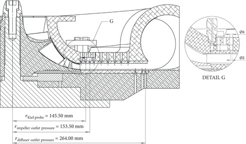
The maximum measurement uncertainties were 46 N for axial thrust, 2.19 kPa for diffuser outlet pressure, and 0.86 kPa for impeller outlet pressure. The axial thrust was measured with an active magnetic bearing control software, which was calibrated with the load cell. The mass of the shaft and the axial thrust of the fan, which cooled down the electric motor, were accounted for in the net axial thrust calculations. The effect of the fan was tested separately, without the compressor impeller. The axial thrust of the fan was approximately 15% of the compressor’s axial thrust at the compressor’s design point.
The effect of thermal expansion on the axial thrust measurement was tested before and after the 2.5-hour test period. Before the test period, the measured axial thrust of the cold nonrotating compressor was 26 N, and after the test period, the axial thrust of the nonrotating compressor was -49 N; the difference between these values was 75 N. As the measurement uncertainty of the axial thrust was 46 N and the effect of thermal expansion (75 N) was less than 6% of the axial thrust measured during the compressor operation (1.3–2.2 kN), it can be concluded that the effect of thermal expansion was negligible in this study. The measured operating points are presented in Table 1 and in the compressor performance map in Figure 3.
| Point | n (Hz) |
qm (kg/s) |
p1 (kPa) |
T1 (°C) |
p3 (kPa) |
pamb (kPa) |
|---|---|---|---|---|---|---|
| 9 | 462 | 1.57 | 94.5 | 23.8 | 226.2 | 100.2 |
| 8 | 461 | 1.77 | 94.1 | 24.6 | 216.9 | 100.2 |
| 7 | 461 | 2.06 | 92.7 | 25.3 | 201.5 | 100.2 |
| 6 | 393 | 1.31 | 96.9 | 20.3 | 184.3 | 100.2 |
| 5 | 392 | 1.53 | 95.7 | 20.8 | 176.1 | 100.3 |
| 4 | 392 | 1.76 | 94.7 | 21.5 | 165.3 | 100.3 |
| 3 | 323 | 1.06 | 98.0 | 18.4 | 152.5 | 100.3 |
| 2 | 323 | 1.25 | 97.3 | 18.9 | 146.8 | 100.3 |
| 1 | 322 | 1.45 | 97.3 | 18.6 | 140.0 | 100.3 |
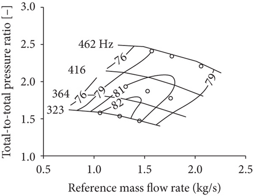
3. Analytical Methods
Different methods have been presented for estimating axial thrust by applying Newton’s second law. Below, the methods proposed by Nguyen-Schäfer [11], Japikse [4], and Larjola [5] are presented. In addition, the theoretical prediction for the pressure distribution in a labyrinth seal proposed by Kearton [9] is shown.
3.1. Nguyen-Schäfer
| Pressure at the impeller inlet | p1 | 94.5 kPa |
| Temperature at the impeller inlet | T1 | 297 K |
| Pressure at the compressor outlet | p5 | 231.2 kPa |
| Impeller inlet hub diameter | d1,h | 40.5 mm |
| Impeller inlet shroud diameter | d1,s | 134.9 mm |
| Impeller outlet diameter | d2 | 270.9 mm |
| Shaft diameter | d0 | 32.0 mm |
| Specific enthalpy increase, impeller | Δhimp | 116.4 kJ/kg |
| Specific enthalpy increase, stage | Δhst | 150.7 kJ/kg |
| Ratio of specific heats | γ | 1.4 |
| Specific gas constant | Rair | 287 J/kg K |
| Mass flow rate | qm | 1.57 kg/s |
The discrepancy between the axial thrust estimated using Nguyen-Schäfer’s method and the axial thrust estimated using CFD was less than 10% for an automotive turbocharger [11].
3.2. Japikse
The fraction is generally simplified to be constant in the range of 0.5 to 1.0, but it can be expressed as a function of radius. In this study, a constant fraction f of 0.5 is used.
| Pressure at the impeller inlet, hub | p1,h | 94.5 kPa |
| Pressure at the impeller inlet, shroud | p1,s | 94.5 kPa |
| Pressure at the impeller inlet | p1 | 94.5 kPa |
| Temperature at the impeller inlet | T1 | 297 K |
| Pressure (just ahead of the seal), shroud | 94.5 kPa | |
| Pressure at the impeller outlet | p2 | 199.4 kPa |
| Temperature at the impeller outlet | T2 | 412 K |
| Pressure just ahead of the seal, back disk | 100.2 kPa | |
| Impeller inlet hub diameter | d1,h | 40.5 mm |
| Impeller inlet shroud diameter | d1,s | 134.9 mm |
| Impeller outlet diameter | d2 | 270.9 mm |
| Shaft diameter | d0 | 32.0 mm |
| Mass flow rate | qm | 1.57 kg/s |
| Rotational speed | n | 462 Hz |
| Fraction | f | 0.5 |
Japikse [4] does not give any estimation for the pressures just ahead of the seal on either the shroud side p1′ or the back disk side p0′. However, in this paper, the impeller is unshrouded and has no seal on the shroud side. Therefore, the pressure at the impeller inlet p1 is used as the pressure p1′ on the shroud side, and the ambient pressure pamb is used as the pressure ahead of the seal on the back disk side.
Under Japikse’s method [4], the axial thrust is calculated using the average pressure in the shroud and back disk cavities, even though the pressure distribution could be written as a function of radius.
3.3. Larjola
| Pressure at the impeller inlet | p1 | 94.5 kPa |
| Temperature at the impeller inlet | T1 | 297 K |
| Total pressure at the impeller outlet | pt2 | 263.9 kPa |
| Pressure at the impeller outlet | p2 | 199.4 kPa |
| Temperature at the impeller outlet | T2 | 412 K |
| Ambient pressure | pamb | 100.2 kPa |
| Impeller inlet hub diameter | d1,h | 40.5 mm |
| Impeller inlet shroud diameter | d1,s | 134.9 mm |
| Impeller outlet diameter | d2 | 270.9 mm |
| Impeller outlet passage height | b2 | 12.2 mm |
| Shaft diameter | d0 | 32.0 mm |
| Ratio of specific heats | γ | 1.4 |
| Specific gas constant | Rair | 287 J/kg K |
| Mass flow rate | qm | 1.57 kg/s |
| Rotational speed | n | 462 Hz |
| Boundary layer blockage factor | B | 0.1 |
| Fraction, back disk | f | 0.5 |
The net axial thrust is calculated using (17).
3.4. Kearton
| p1/p0 | F |
|---|---|
| 1.00 | 1.00000 |
| 0.95 | 0.95116 |
| 0.90 | 0.90425 |
| 0.85 | 0.85872 |
| 0.80 | 0.81400 |
In the studied centrifugal compressor, the radial distance between any two adjacent rings a is 1.5 mm, the axial clearance is 2.5 mm, the total number of rings n is 16, and the radius of the outermost ring r is 94.5 mm.
4. Numerical Methods
The axial thrust is estimated based on the pressure distributions obtained from the numerical simulation. The inlet pipe, impeller, vaneless diffuser, and back disk cavity are modeled with ANSYS CFX 19.2. The boundary conditions are based on experimental data of nine different operating points (Table 1). A total pressure of 92.7–98.0 kPa and a temperature of 18.4–25.3°C with a turbulence intensity of 5% are defined at the computational domain inlet. At the outlets of the diffuser and back disk cavity, static pressures of 140.0–226.2 kPa and 100.2–100.3 kPa are defined, respectively. According to the findings in [13], the interface between the impeller and diffuser is located at 1.02r2. Because the interaction between the impeller and the vaneless diffuser is weak, the frozen rotor approach is used to model the interfaces between the stationary and rotating parts. The k − ω SST model is chosen to model turbulence based on the validation for turbomachinery applications [14] and the recommendation in [15]. In the vaneless diffuser, a structured mesh is used, and an unstructured mesh is used in the impeller and back disk cavity. On average, the dimensionless wall distance y+ is below unity. The meshes of the computational domains with and without the labyrinth seal are shown in Figure 4.
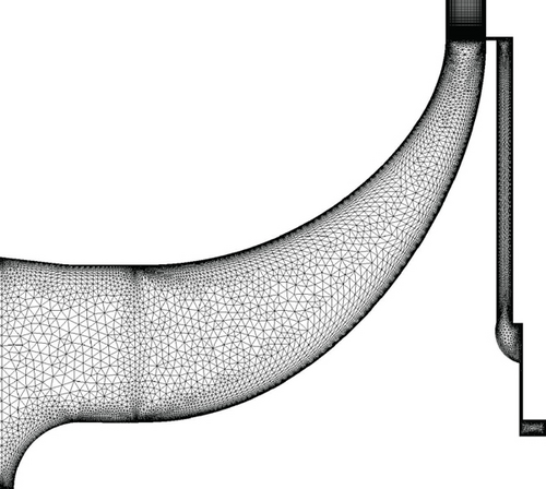
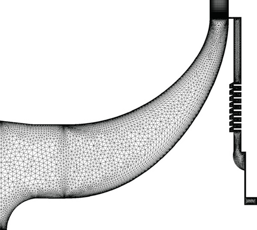
The method proposed by Larjola can be modified according to whether the cases neglect or account for the labyrinth seal. Therefore, two cases, neglecting and accounting for the labyrinth seal, respectively, are studied numerically. The compressor geometry without the labyrinth seal is used in the mesh independence study. To study mesh independence, the design point of the compressor is modeled. The comparison between three different meshes (fine with 60 million elements, medium with 25 million elements, and coarse with 11 million elements) is shown in Figure 5, which presents the pressure distributions on the shroud and back disk sides. Different meshes give similar results, and the pressure distributions match well with the design values. The medium mesh with 25 million elements was chosen for the studies. The gray area in Figure 5 presents the discretization error estimated with the method proposed in [16].

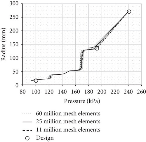
Axial thrust caused by the pressure forces on the shroud and back disk sides is more significant than the axial thrust caused by the impulse force. Therefore, it is more important that the pressure distribution is correctly predicted by the numerical model, and the underestimation of the compressor mass flow rate by the numerical model does not significantly affect the net axial thrust.
Table 6 presents the modeled mass flow rate at the compressor inlet when the back disk cavity is modeled without and with the labyrinth seal. Results in Table 6 indicate that the leakage flow rate out of the back disk cavity reduces by only approximately 1 g/s (0.1% of the total mass flow rate) when the labyrinth seal is modeled, compared to when the cavity does not include the labyrinth seal. According to the numerical results, the leakage mass flow rate is in the range of 5 to 10 g/s, which is 0.4–0.7% of the compressor’s mass flow rate. Kearton’s [9] theory predicts that the leakage mass flow rate is ten times larger than the numerical result, namely, 79–159 g/s (5–10% of the compressor’s mass flow rate). The leakage mass flow rate of the studied compressor is approximately 1–2% of the compressor’s mass flow rate. Therefore, the modeled value is closer to the actual one than the value based on Kearton’s [9] theory. In (41), the pressures at the seal inlet and outlet are, respectively, the measured static pressure at the impeller outlet and the ambient pressure. Because the pressures exactly at the seal inlet and outlet are not measured, the use of impeller outlet and ambient pressure values results in an error in the leakage mass flow estimation, as will be demonstrated later.
| Without seal | With seal | ||||
|---|---|---|---|---|---|
| Point | Exp. (kg/s) |
CFD (kg/s) |
Difference (%) |
CFD (kg/s) |
Difference (%) |
| 9 | 1.57 | 1.493 | -4.7% | 1.492 | -4.8% |
| 8 | 1.77 | 1.620 | -8.5% | 1.619 | -8.5% |
| 7 | 2.06 | 1.828 | -11.2% | 1.828 | -11.2% |
| 6 | 1.31 | 1.301 | -0.9% | 1.299 | -1.0% |
| 5 | 1.53 | 1.442 | -6.1% | 1.441 | -6.1% |
| 4 | 1.76 | 1.648 | -6.5% | 1.649 | -6.4% |
| 3 | 1.06 | 1.081 | 1.5% | 1.079 | 1.3% |
| 2 | 1.25 | 1.237 | -1.0% | 1.238 | -1.0% |
| 1 | 1.45 | 1.454 | 0.5% | 1.454 | 0.6% |
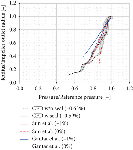
The difference between the modeled and measured mass flow rates is in the range of 0.5% (point 1) to 11.2% (point 7). However, the modeled total-to-total pressure ratio πt1−t2 is much closer to the measured one, the maximum difference being 2.6% (points 5 and 8), as shown in Table 7. In Figure 6, the modeled pressure distribution on the back disk side is compared to the numerical results in the case of a centrifugal compressor [3] and to the experimental results in the case of a radial pump [8]. The relative values of the leakage mass flow rates are given in parentheses in the legend. The modeled pressure distributions with and without the labyrinth seal are similar to those presented in [3], but different cavity geometries cause differences.
| Without seal | With seal | ||||
|---|---|---|---|---|---|
| Point | Exp. (-) |
CFD (-) |
Difference (%) |
CFD (-) |
Difference (%) |
| 9 | 2.79 | 2.73 | -2.2% | 2.73 | -2.2% |
| 8 | 2.69 | 2.62 | -2.6% | 2.62 | -2.6% |
| 7 | 2.54 | 2.48 | -2.3% | 2.48 | -2.4% |
| 6 | 2.16 | 2.11 | -2.4% | 2.11 | -2.4% |
| 5 | 2.08 | 2.03 | -2.6% | 2.03 | -2.6% |
| 4 | 1.98 | 1.95 | -1.8% | 1.95 | -1.8% |
| 3 | 1.69 | 1.67 | -1.0% | 1.67 | -1.0% |
| 2 | 1.64 | 1.62 | -1.1% | 1.62 | -1.1% |
| 1 | 1.57 | 1.56 | -0.6% | 1.56 | -0.6% |
5. Comparison of the Analytical Methods
The axial thrust values and pressure distributions from the abovementioned analytical methods are compared to the measurements and modeled results. The nine measured operating points presented in Table 1 and the data presented in Tables 2–4 are substituted in the equations of the three methods to estimate the axial thrust. First, the net axial thrust estimated using these methods is compared to the measured and modeled values. Second, the pressure distributions estimated by the methods are compared to the measured values, the modeled distributions, and the theoretically predicted distributions.
5.1. Net Axial Thrust
When the parameters of the point of maximum axial thrust (point 9 in Table 1 and the data in Tables 2–4) of the studied compressor are substituted in the abovementioned equations, three axial thrust calculation methods give the results presented in Table 8. The results given by these analytical methods are compared to the measured axial thrust in the same table, and the comparison indicates that Larjola’s method gives the best, albeit a still underestimated, prediction.
| Method | Without leakage/seal (kN) | With leakage/seal (kN) |
|---|---|---|
| Nguyen-Schäfer | 3.27 | 0.65 |
| Japikse | 0.91 | |
| Larjola | 2.71 | 1.93 |
| Measurement | 2.19 ± 0.046 |
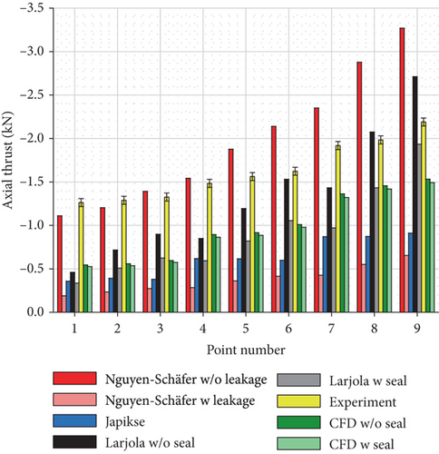
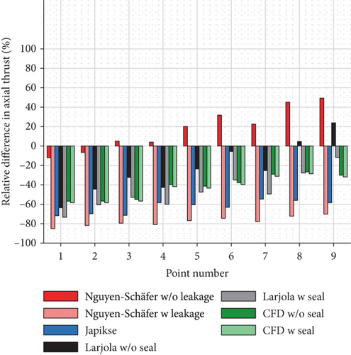
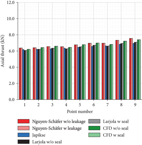
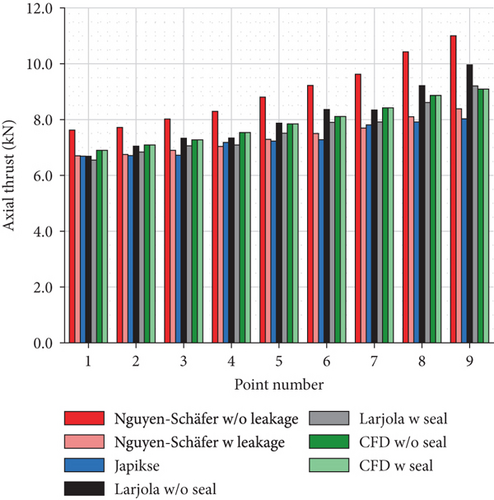
The estimations for other operating points made with three analytical methods and numerical model are shown in Figure 7. In Figure 7(a), the axial thrust estimations are compared to the measured axial thrust. In Figure 7(b), the relative difference between the estimations and the measured axial thrust is presented. The results in Figure 7 indicate that Nguyen-Schäfer’s method gives relatively close estimations for axial thrust at low rotational speeds, but it overestimates the axial thrust by 49% at the point of maximum measured axial thrust (point 9) when leakage is neglected. When leakage is accounted for, Nguyen-Schäfer’s method underestimates the axial thrust by 70–85%. Japikse’s method underestimates the axial thrust by 55–72%. When the labyrinth seal is neglected, the greatest underestimation under Larjola’s method is 64% (point 1) and the greatest overestimation is 24% (point 9). The most realistic case is Larjola’s method with a labyrinth seal as the estimation in this case deviates from the measured axial thrust by only -12% at the point of maximum axial thrust (point 9). The results of the numerical simulation underestimate the axial thrust by 26–58%.
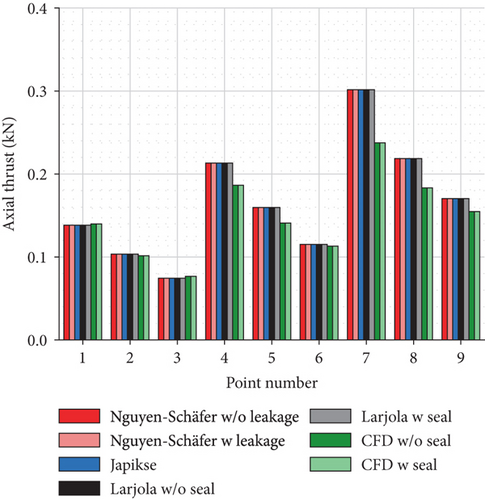
The estimation of the net axial thrust can be divided into three parts, namely, the pressure force acting on the shroud side, the pressure force acting on the back disk side, and the impulse force. These three forces, estimated by the three methods and numerical simulations, are presented in Figure 8. As mentioned above, the impulse force does not contribute to the net axial thrust as significantly as the pressure forces. Figure 8(a) indicates that all the methods and numerical models give an almost equal estimation of the pressure force on the shroud side. Figure 8(c) indicates that the numerical results of the impulse force differ slightly from the estimations of the three methods, which results from the difference in the modeled mass flow rate (Table 6). The most significant difference in the axial thrust estimation occurs in the pressure force on the back disk side (Figure 8(b)).
5.2. Pressure Distributions
The difference between the axial thrust estimations, especially on the back disk side, results from the estimated pressure distribution as the axial thrust is a product of pressure and area. The pressure distributions on the shroud and back disk sides of the studied compressor are sketched in Figure 9 for the design point (point 8). The pressure distributions on the shroud and back disk sides, with and without the leakage/labyrinth seal, are presented in Figures 10–12. The figures present two extreme points (operation points 1 and 9, listed in Table 1) since the other points fall within these two extremes. Figure 10 presents the pressure distribution on the shroud side estimated with the three methods and CFD. The measured static pressures at the impeller inlet, impeller outlet, and diffuser outlet are also presented. Figure 11 presents the pressure distribution on the back disk when leakage and the labyrinth seal are neglected. Figure 12 presents the pressure distribution on the back disk when leakage and labyrinth seal are accounted for.
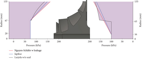
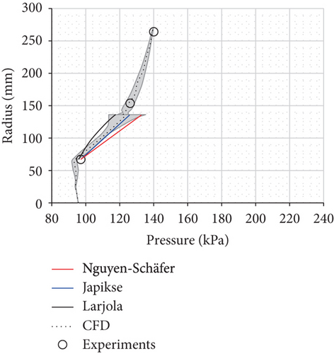
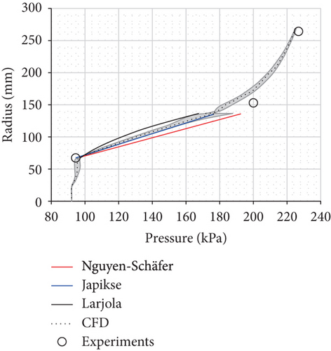
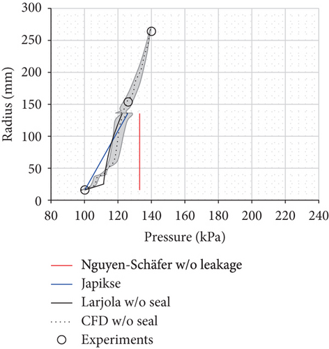
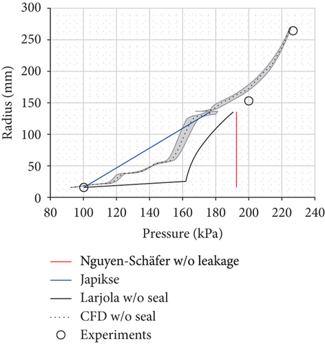
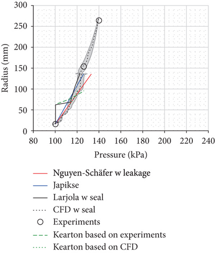

Figure 10 indicates that the pressure distribution on the shroud side does not deviate greatly between the different methods and the numerical model. However, the linear assumption of Japikse’s method with the fraction f of 0.5 gives a better distribution than that predicted by other methods.
Figure 11 clearly shows that the assumption of constant pressure in the back disk cavity is not valid in the studied centrifugal compressor, even though it might be valid in the case of turbochargers [11]. The assumption of nearly constant pressure on the back disk surface results in overestimated pressure distribution on the back disk side and axial thrust under Nguyen-Schäfer’s method. However, if the leakage flow through the back disk cavity is accounted for, as under Nguyen-Schäfer’s method in Figure 12, the method underestimates the axial thrust because of the overestimated pressure distribution on the shroud side (Figure 10).
Japikse’s method underestimates the pressure distribution on the cavity side, especially when the labyrinth seal is not modeled (Figure 11). The underestimation of the pressure force on the back disk results in the underestimated net axial thrust at all studied points.
Larjola’s method estimates the pressure distribution on the shroud side similarly to the numerical model and the methods proposed by Nguyen-Schäfer and Japikse. The axial labyrinth seal is assumed under Larjola’s method, but the radial labyrinth seal is used in the studied compressor. Despite the radial labyrinth seal, Larjola’s method gives the closest estimation of the axial thrust value when compared to the measurement in point 9, even though the pressure distribution on the back disk side does not follow a numerical result.
If the measured impeller outlet pressure and ambient pressure are used to estimate the pressure distribution according to Kearton’s [9] theory, the pressure distribution (green dashed line in Figure 12) deviates significantly from the numerical results. Also, the leakage mass flow rate (79–159 g/s) is more than ten times larger than the numerical result (5–10 g/s). However, the theoretical pressure distribution (green dotted line) equals the numerical result if the numerical prediction for the seal inlet and outlet pressures is used. The close match between the theoretical and numerical pressure distributions is an encouraging result when there are no pressure measurements at the seal inlet and outlet. However, in order to keep the method simple, the CFD results cannot be included in the axial thrust estimation method, because otherwise the CFD modeling would be required prior to the axial thrust estimation.
The pressure distributions in Figure 12 indicate that close to the design point (point 9), the assumption of the pressure reduction to ambient pressure at the end of the labyrinth seal (at the radius of 62.5 mm) cancels out the effect of the overestimated pressure in the labyrinth seal on the pressure force. Hence, Larjola’s method gives an estimation of the net axial thrust that is in good agreement with the measured one. However, at other points, the assumption of the ambient pressure between the shaft and the end of the labyrinth seal results in an underestimated pressure force on the back disk side and net axial thrust (point 1 shown in Figure 12).
The main drawbacks of the available methods are that they tend to underestimate the maximum axial thrust, and they require data that are not available at the preliminary design of a turbomachine. The accurate prediction of the pressure distribution on the back disk side causes the most difficulties in the axial thrust estimation. The conclusion, based on the results presented above, is that Larjola’s method works best at the point of maximum axial thrust (point 9), but it fails to predict the axial thrust at low rotational speeds. Since bearing design is aimed at estimating the maximum axial thrust, the accurate prediction of the axial thrust at the point of high rotational speeds and a low flow rate is more important than it is at lower rotational speeds, where the axial thrust values are lower.
To avoid the underestimation of the axial thrust, which leads to large safety margins and oversized bearings, a more accurate axial thrust estimation method is required. Thus, a new hybrid method is proposed for the estimation of the maximum axial thrust in the preliminary design phase of a radial turbomachine. The hybrid method is presented in the following section.
6. Hybrid Method
The hybrid method only requires data that are available at the preliminary design of a turbomachine. The required parameters are shown in Table 9.
| Centrifugal compressor/pump | Radial inflow turbine | |||
| Pressure at the impeller inlet | p1 | Pa | p1 | Pressure at the rotor inlet |
| Temperature at the impeller inlet | T1 | K | T1 | Temperature at the rotor inlet |
| Pressure at the impeller outlet | p2 | Pa | p2 | Pressure at the rotor outlet |
| Temperature at the impeller outlet | T2 | K | T2 | Temperature at the rotor outlet |
| Ambient pressure | pamb | Pa | pamb | Ambient pressure |
| Impeller inlet hub radius | r1,h | m | r2,h | Rotor outlet hub radius |
| Impeller inlet shroud radius | r1,s | m | r2,s | Rotor outlet shroud radius |
| Impeller outlet radius | r2 | m | r1 | Rotor inlet radius |
| Labyrinth seal (outer) radius | rL | m | rL | Labyrinth seal (outer) radius |
| Shaft radius | r0 | m | r0 | Shaft radius |
| Mass flow rate | qm | kg/s | qm | Mass flow rate |
| Rotational speed | n | rpm | n | Rotational speed |
| Fraction, shroud and back disk | f | 0.5 | f | Fraction, shroud and back disk |
7. Validation Cases
7.1. Centrifugal Compressor
The centrifugal compressor designed and measured at LUT and presented in Section 2 is used as a validation case. The maximum measured axial thrust is 2190 N, and the measurement uncertainty of axial thrust is 46.3 N. Both the predesign parameters and the experimental results of the point of maximum axial thrust are used in the hybrid method; these are shown in Table 10.
| p1 | T1 | p2 | T2 | pamb | r1,h | r1,s | r2 | rL | r0 | qm | n | |
|---|---|---|---|---|---|---|---|---|---|---|---|---|
| kPa | K | kPa | K | kPa | mm | mm | mm | mm | mm | kg/s | rpm | |
| Predesign | 93.6 | 283 | 198.9 | 357 | 100.3 | 20.3 | 67.5 | 135.5 | 96.0 | 16.0 | 1.57 | 27,660 |
| Experimental | 94.5 | 297 | 199.4 | 412 | 100.2 | 20.3 | 67.5 | 135.5 | 96.0 | 16.0 | 1.57 | 27,725 |
7.2. Radial Pump
The radial pump [17, 18] had 2-dimensional impeller blades, a shrouded impeller, and a seal on the shroud side. According to the drawings [17, 18], there is no labyrinth seal in the back disk cavity. In this paper, the axial thrust is estimated at the design point of the pump since all the required data are available at that point. At the design point, the measured total pressure rise in the impeller is 23.3 kPa and the measured impeller outlet velocity is 3.0 m/s [17]. The incompressible flow and water density of 1000 kg/m3 are assumed when estimating the static pressure of 120.2 kPa at the impeller outlet. At the design point, the measured axial thrust is 428 N and the measurement uncertainty of the axial thrust is 2.7 N [18]. The parameters of the radial pump used in the hybrid method are shown in Table 11.
| p1 | p2 | pamb | r1,s | r2 | r0 | qm | n |
|---|---|---|---|---|---|---|---|
| kPa | kPa | kPa | mm | mm | mm | kg/s | rpm |
| 101.3 | 120.2 | 101.3 | 50.8 | 101.6 | 38.1 | 6.3 | 620 |
7.3. Gas Turbines
The results presented in Section 5 show that the analytical methods have difficulties in predicting the axial thrust of a single turbomachine. The task is even more difficult when the centrifugal compressor and the radial turbine are attached to the same shaft. To show the superiority of the hybrid method, the predesign parameters of two gas turbines from Aurelia Turbines Oy, Finland, are used in the hybrid method to estimate the net axial thrust. The predesign parameters are proprietary information and are thus not presented in this paper. The gas turbines are low-pressure and high-pressure turbines providing 400 kWe in total. They are later referred to as gas turbines 1 and 2, respectively. The predicted net axial thrust of the gas turbines is compared to the experimental results from Aurelia Turbines Oy. In this paper, the axial thrust is estimated at the design point of the compressors and turbines since the experimental data are available at that point.
8. Validation Results
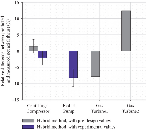
The new hybrid method is compared to the other analytical methods using the four validation cases. The results of the comparison are shown in Figure 13(a). The three previously published methods predict that the axial thrust is tens of times higher or lower than the measured thrust. In Figure 13(b), only the results of the hybrid method are shown when the preliminary design values (gray color) and experimental data (purple color) are used as input data. The maximum relative difference between the measurement and the prediction of the hybrid method of 13% is achieved with the high-pressure gas turbine. For the centrifugal compressor, radial pump, and low-pressure gas turbine, the relative difference between the predicted and measured thrust is less than 10%.

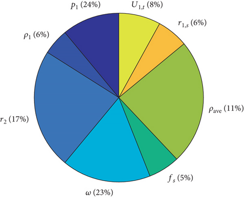
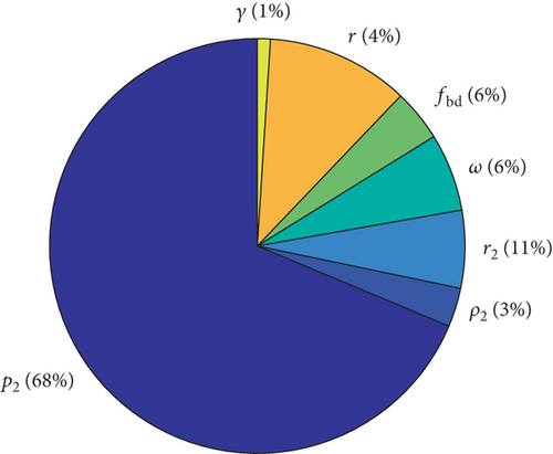
The sensitivity of the input data parameters of the hybrid method on the predicted pressure distributions on the shroud side (48 and 49) and on the back disk side (54, 55, and 56) was analyzed similarly as with the measurement uncertainty, i.e., by calculating the partial derivatives. Figure 14(a) presents the effect of the parameters in (48 and 49) on the pressure distribution on the shroud side. Figure 14(b) presents the effect of the parameters in (54, 55, and 56) on the pressure distribution on the back disk side. The effect on the pressure distribution is more equally divided between different parameters on the shroud side than on the back disk side. On the back disk side, the impeller outlet pressure (rotor inlet pressure in the case of the turbine) affects mostly the pressure distribution. The fractions fs and fbd on the shroud and back disk sides affect the pressure distributions by only 5 and 6%, respectively.
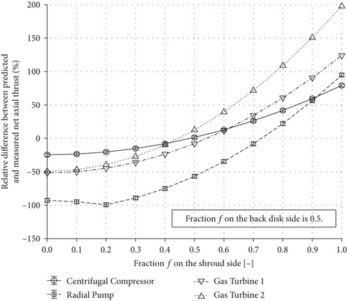
The fractions fs and fbd on the shroud and back disk sides have only a marginal impact on the pressure distributions, as shown in Figure 14. Generally, the average circumferential velocity in the back disk cavity is half the impeller’s local circumferential velocity (f = 0.5) [3–5]. The sensitivity of the net axial thrust on the fraction on the shroud side is analyzed in Figure 15, whereby the fraction on the back disk side remains constant while the fraction on the shroud side varies. The results in Figure 15 indicate that the fraction of 0.5 on the shroud side gives the best prediction of the net axial thrust in the case of the centrifugal compressor and the gas turbines. In the case of the radial pump, the fraction of 0.7 gives a better prediction than the fraction of 0.5.
9. Conclusions
This study compared three analytical axial thrust estimation methods to the numerical and experimental results to analyze their accuracy. According to the results, Japikse’s method gave the most accurate estimation for the pressure distribution at the shroud and Larjola’s method gave the most accurate estimation for the pressure distribution on the back disk side from the outlet of the impeller of the centrifugal compressor to the outer radius of the radial labyrinth seal. Compared to the methods proposed by Japikse and Nguyen-Schäfer, the prime advantage of Larjola’s method was that the pressure distribution was not approximated to change linearly in the back disk cavity; rather, it was estimated to vary as a function of radius.
To offer a simple and more accurate axial thrust estimation tool for designers, engineers, and scientists working with radial turbomachines, the best elements of the compared analytical methods were combined into the hybrid method and the linear change in pressure was assumed from the outer radius of the radial labyrinth seal to the shaft. The hybrid method was validated against the experimental data of the centrifugal compressor and radial pump. The new method showed its superior predictive capability also in the case of two gas turbines. The maximum deviation between the predicted axial thrust by the hybrid method and the measured one was less than 13%, whereas the other methods deviated by tens of percent. Therefore, the hybrid method improves the turbomachine design process and bearing sizing because it predicts the axial thrust at the operating point of maximum expected thrust more accurately than the other methods. It is also a simpler approach because it only requires data that are available at the preliminary design phase.
As future work, it is recommended to extend the validation of the hybrid method to different radial turbomachines including multistage machines.
The hybrid method is shared under the CC BY-SA 4.0 license.
Conflicts of Interest
The authors declare that they have no conflicts of interest.
Open Research
Data Availability
The numerical and experimental data of the centrifugal compressor modeled and measured at the Lappeenranta-Lahti University of Technology LUT, Finland, and used to support the findings of this study are available from the corresponding author upon request. The hybrid method is shared under the CC BY-SA 4.0 license in the publication repository of the Lappeenranta-Lahti University of Technology.


