Flink-ER: An Elastic Resource-Scheduling Strategy for Processing Fluctuating Mobile Stream Data on Flink
Abstract
As real-time and immediate feedback becomes increasingly important in tasks related to mobile information, big data stream processing systems are increasingly applied to process massive amounts of mobile data. However, when processing a drastically fluctuating mobile data stream, the lack of an elastic resource-scheduling strategy limits the elasticity and scalability of data stream processing systems. To address this problem, this paper builds a flow-network model, a resource allocation model, and a data redistribution model as the foundation for proposing Flink with an elastic resource-scheduling strategy (Flink-ER), which consists of a capacity detection algorithm, an elastic resource reallocation algorithm, and a data redistribution algorithm. The strategy improves the performance of the platform by dynamically rescaling the cluster and increasing the parallelism of operators based on the processing load. The experimental results show that the throughput of a cluster was promoted under the premise of meeting latency constraints, which verifies the efficiency of the strategy.
1. Introduction
With the explosive development of mobile computing devices, the Internet of Things, and virtual reality (VR) [1], a large amount of data that requires immediate processing with extremely low latency has been generated. Meanwhile, big data stream processing systems (DSPSs) provide exact real-time data processing services. The statistical data from Seagate show that the total amount of data will reach 163 ZB before 2025 [2], a quarter of which will be generated by mobile information devices and require real-time processing [3]. Therefore, to handle real-time mobile streaming data that exhibit volatility, burstiness, disorder, and infiniteness [4], DSPSs have been widely applied in multiple scenarios of big data stream computing, especially for mobile data processing. In addition, due to advantages such as low latency, high-throughput performance, efficient fault tolerance [5, 6], and elegant backpressure mechanisms, Apache Flink [7, 8] has been widely used in industry and has drawn increasing attention in academia, making it superior to similar software programs and one of the most popular DSPSs in the mobile data-processing domain.
However, under stream computing fluctuations, Flink has disadvantages in terms of elasticity and scalability. The input load of stream processing usually fluctuates drastically over time, but the Flink cluster cannot be promptly rescaled. Therefore, a performance decline always occurs under peak load due to the insufficiency of computing resources, while energy overuse always occurs during times of low load. Since Flink does not provide an elastic resource-rescheduling strategy, performance decline and energy overuse have become serious challenges that have drawn much attention from the open-source community.
- (1)
We propose abstracting the stream computing topology as the model of a flow network. By taking it as the basis for building the resource allocation model and data redistribution model, we provide a theoretical foundation for developing Flink-ER.
- (2)
We propose the capacity detection algorithm based on the flow-network model. The algorithm calculates the initial capacity based on the network transmission performance and adjusts it by periodic feedback to determine an appropriate capacity for each edge, thus laying the foundation for the elastic resource reallocation algorithm.
- (3)
We propose the elastic resource reallocation algorithm based on the resource allocation model. This algorithm optimally dispatches the increasing load and creates the resource-rescheduling plan by identifying the performance bottleneck, thus improving the performance by effectively utilizing computing resources.
- (4)
We propose the data redistribution algorithm based on the data redistribution model. This algorithm reduces the overhead required to execute the resource-rescheduling plan by improving the efficiency of the checkpoint and restore process in Flink.
The rest of this paper is organized as follows. Section 2 presents models built based on the flow network as the theoretical foundation of Flink-ER. Section 3 details the three algorithms of the elastic rescaling strategy and its implementation. Section 4 evaluates the performance improvement and overhead of the strategy by comparing it with strategies from closely related studies. Section 5 introduces the strengths and weaknesses of related works. Section 6 briefly concludes the paper and discusses future work.
2. Model Topology
In this section, the basic paradigm of big data stream computing is first presented and modeled as a flow network by analyzing the capacity and flow of every edge in the DAG. Second, the resource allocation model is built based on a flow network to identify the bottleneck of a cluster and create the resource-rescheduling plan. Finally, the data redistribution model is developed by considering the features of stateful data in stream computing as a theoretical foundation for the data redistribution algorithm.
2.1. Stream Computing Paradigm
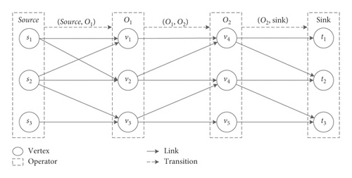
In the big data stream computing platform, data are directly processed in the memory of the computing nodes, whereas Figure 1 shows the user-defined function is used as an operator and the unprocessed data are sent by the source, sequentially processed by the operators and finally written into storage by a sink. Generally, the data source reads data from a message queue such as Kafka, while a data sink writes results into the Hadoop distributed file system (HDFS) or Redis et al. according to the practical requirements.

However, in parallel stream processing engines such as Flink, the corresponding logic of each operator is deployed and executed in multiple nodes called vertices. Since Apache Flink adopts a master-slave architecture, the streaming job is represented as a JobGraph, as shown in Figure 1. However, in the parallel streaming processing platform, the ExecutionGraph of a job, as presented in Figure 2, serves as a guide for the JobManager to deploy the job and schedule tasks. Figure 2 illustrates that the topology structure of a streaming job is a DAG in which s represents the source, vi represents vertices for processing the data, ti represents the sinks used to output results, and (vi, vj) represents links used to transmit data between vertices. Generally, given that the processing logic of the operator Oi is deployed to vertices v1, v2, …, vm, these vertices are called the instances of the operator, defined as vi ∈ Oi. In addition, given that the data transition between operators Oi and Oj is mapped by links (va, vb), (vc, vd), …, (vn, vm), these links are called the instances of transition (Oi, Oj), defined as (vn, vm) ∈ (Oi, Oj). Therefore, the relationships between the logical operator and physical vertex and between the logical transition and physical links are clarified and then used in the following descriptions.
2.2. Model of Flow Network
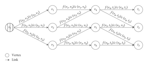
The stream computing paradigm shows that the data transition performance of edges and the processing capacity of vertices are crucial for achieving good cluster performance. The data that are not processed on time are stored in the buffer of the nodes and lead to data accumulation in Kafka. In other words, a lack of processing capability and redundancy of the input load lead to a latency increase. Therefore, the source corresponding to the most accumulated partition in Kafka formulates the flow-network paradigm [9]. For example, suppose that s2 in the topology of Figure 2 leads to the most accumulations; then, the corresponding flow network is as presented in Figure 3.
-
Algorithm 1: Capacity detection algorithm.
-
Input:
-
Topology of the job: T = {V, E}
-
Output:
-
Flow network of the job: G = {V, E}
-
Begin
-
Initialize the flow network from the topology.
-
foreach (vi, vj) ∈ G.E do
-
Calculate the initial capacity of the edge according to equation (10).
-
end foreach
-
if S.f > 0 then
-
/∗Feedback regulation executes when a processing load exists∗/
-
foreach vj ∈ G.V do
-
if avg(latency) > θ and f(vi, vj) ≤ c(vi, vj) then
-
c(vi, vj) ⟵ c(vi, vj) – η/∗Reduce the capacity∗/
-
else if avg(latency) << θ && f(vi, vj) ≈ c(vi, vj) then
-
c(vi, vj) ⟵ c(vi, vj) + η/∗Enlarge the capacity∗/
-
end if
-
end foreach
-
end if
-
return G
-
End
According to the flow-network model, c(vi, vj) is the peak value of the data transition rate, which represents the transition capability of the link and the processing capability of the corresponding vertex. It provides the foundation of the model for the elastic resource allocation algorithm, as presented in Section 4.2, to identify the performance bottleneck of the cluster and to reschedule computing resources. Accurate detection of the capacity of each edge is very important; thus, a capacity detection algorithm is proposed in Section 4.1 to calculate the capacity of each edge, construct the model of the flow network, and lay a foundation for creating the resource-rescheduling plan.
As shown in Figure 4, given the flow network G = (V, E) with stream f, the corresponding improving network of G on f is Gf = (Vf, Ef), which describes the optimization space for the throughput of the cluster. Moreover, Vf = V is the set of vertices and Ef is the set of edges in the topology. For each edge (vi, vj) ∈ E in the improving network, there is an improve space and a reduce space for the edge. The improve space p(vi, vj) = c(vi, vj) − f(vi, vj) represents the space within which the data transition speed of the corresponding edge can be increased. The reduce space r(vi, vj) = f(vi, vj) represents the space within which the data transition speed of the corresponding edge can be decreased.
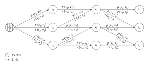
Specifically, in the original flow network, the flow f(vi, vj) represents the data transition speed on the corresponding edge, and c(vi, vj) is the maximum data transition speed. Accordingly, the data transition speed of the corresponding edge can be no larger than the improve space p(vi, vj), while the data transition rate can be no smaller than the reduce space. In conclusion, the improve and reduce spaces represent the ranges within which the data transition rate of the corresponding edge can be increased or reduced, respectively. Therefore, the processing load distribution can be optimized and the data processing efficiency can be improved by making full use of existing computing resources.
The promotion capacity in the same direction as the original network is the difference between the capacity and the flow of each edge, which represents the space for improving the capacity of the original network. By contrast, the promotion capacity in the opposite direction of the original network represents the space for reducing the transition load of the corresponding edges. Therefore, we can optimize the load distribution among nodes according to the promotion capacity of every edge. Meanwhile, the optimization path with the minimum promotion capacity of the edges on the path provides a scheme for promoting the throughput from the source to one of the sinks.
Supposed that G = (V, E) is a flow network with flow f and the corresponding improving network Gf = (Vf, Ef) with optimization path P. Thus, the promoted flow f ↑ fp is also one of the streams of the original network, and the promoted value is |f′| = |f↑fp| = |f| + |fp| > |f|, which means that the promoted flow is always larger than the original flow. Therefore, since we can find a greater flow of the topology by the optimization path, a scheme to promote the value of the stream in the original flow network and to dispatch data more effectively is achieved. Thus, the latency to dispatch stored data in the direction of the optimization path should be reduced when data accumulation is formulated at the source. Therefore, the core idea of Flink-ER is to find the optimization path, dispatch accumulated data, and identify the performance bottleneck.
2.3. Model of Resource Allocation
The mathematical relationships between the processing capability of nodes and the input load in practice are quantified by proposing a flow-network model. However, when the cluster performance declines due to a lack of computing resources, optimization of the data distribution strategy is unnecessary; thus, it is crucial to develop the resource allocation model as a basis of an elastic resource reallocation algorithm.
In particular, the partition with the minimum capacity is the minimum partition of the flow network.
According to the description above, a partition divides the flow network into two parts, for which the source and sinks are always on different sides and the instances of the same operators are always in the same set. Therefore, each partition of the network represents a potential performance bottleneck, where the processing load is beyond the transition capability across the partition. Consequently, partitioning is the most effective way to identify the bottleneck and supply the computing resources necessary to break it accurately.
Let G = (V, E) be a flow network and Gf = (Vf, Ef) be the improving network on stream f. If it does not exit any optimization path in Gf, then there is not any room to improve the throughput; all the computing nodes are fully occupied with data processing tasks, and the cluster meets the conditions of the performance bottleneck. There must be an operator whose instances are not capable of processing incoming data on time due to the lack of computing resources, and f must be the stream with the maximum flow of the network. As a result, there is at least one partition Dmin = (X, Y) as the minimum partition of G that makes |f| = f(X, Y) = c(X, Y) true [10], and this Dmin indicates that the operator lacks computing resources. In other words, the minimum partition represents the actual performance bottleneck of the cluster that is not capable of processing arrival data on time. Therefore, Flink-ER identifies the performance bottleneck through the minimum partition and supplies computing resources to address it.
2.4. Model for Data Redistribution
To address the bottleneck, the job should be rescheduled, and tasks should be migrated among nodes to provide enough computing resources. However, the intermediate results of computing are retained in every node as the stateful data in stateful stream processing, which is the major challenge to propose an elastic resource-scheduling strategy.
With the improved data redistribution model, the scattered stateful data are integrated as several buckets in nodes, which significantly improves the efficiency of the checkpoint and data restore process. Consequently, the data redistribution algorithm is designed based on the model and used to execute the elastic resource-rescheduling plan by adding computing resources and effectively migrating stateful data among nodes.
3. Elastic Resource Reallocation Strategy
Based on the models developed in Section 3, the three core algorithms of Flink-ER are presented in this section. First, the capacity detection algorithm is designed to calculate the capacity of each edge in the flow network by feedback regulation. Second, the elastic resource reallocation algorithm is proposed based on the resource allocation model to optimize the data dispatching strategy, identify the performance bottleneck, and create the resource-rescheduling plan. Finally, the data redistribution algorithm is presented to invoke the resource-rescheduling plan by effectively migrating data to the nodes. Furthermore, the deployment of the strategy and the structure of Flink-ER are presented.
3.1. Capacity Detection Algorithm for Flow Network
According to the definition of the flow network, the capacity value c(vi, vj) represents the processing and transition capability of corresponding vertices and edges, which is crucial to evaluate the performance of a cluster. As a result, an accurate value of the capacity must be acquired to lay the foundation for efficient elastic resource scheduling. Practical experience and the experimental results show that the CPU, RAM, and network bandwidth impact the performance of computing nodes, with the network bandwidth being the determinant factor because the transition overhead contributes the most latency to data processing. Therefore, the algorithm takes network performance as a basis for defining the initial value of the capacity, and it takes the remaining factors into consideration by feedback regulation.
Based on the analysis above, the specific process of the capacity detection algorithm is as follows.
First, as shown in Algorithm 1, the flow network of the topology, which consists of all vertices and edges in the DAG topology, is initialized. Second, the initial capacity c(vi, vj) of every edge is calculated according to equation (10). However, a deviation occurs in the representation of the transition capability of the corresponding edges. Therefore, feedback regulation is executed repeatedly on every edge. If the average processing latency exceeds the user-defined threshold, i.e., the capacity is beyond the exact capability of the vertex, then the capacity is reduced. In contrast, if the average processing latency is far below the user-defined threshold, i.e., resources still exist in the computing nodes, then the capacity is increased. Finally, the capacity of each edge is converted to a value within an ideal range by initial value calculation and continuous feedback regulation.
Therefore, the DAG topology of the job is transformed into a flow network by detecting the capacity of every edge, which provides a modeling foundation for the elastic resource reallocation algorithm to identify the performance bottleneck and create the resource-rescheduling plan. Moreover, η is an important parameter representing the step size of feedback regulation; we will discuss how to acquire the value of η in Section 4.4.
3.2. Elastic Resource Reallocation Algorithm
According to the model of resource allocation and the analysis given above, the elastic resource reallocation algorithm is as follows.
First, as shown in Algorithm 2, the improving network is formulated according to the definition, and the optimization path is sought based on the flow network. Second, the accumulated data are dispatched along the optimization path when there is a path in the improving network to improve the throughput of the cluster. In contrast, when no optimization path exists in the improving network, which means that the unprocessed data arrival rate exceeds the highest throughput of the cluster, then the bottleneck of the cluster is identified by the minimum partition, and extra resources are supplied to improve the processing capability and throughput of the cluster. Finally, the data redistribution algorithm is used to migrate stateful data and reschedule tasks.
-
Algorithm 2: Elastic resource reallocation algorithm.
-
Input:
-
Flow network: G = {V, E}
-
Current flow of the network: f
-
Accumulation of every partition in source: lags[]
-
Output:
-
Rescaled flow network: G′
-
Begin
-
Build the improving network from the flow network.
-
P ← BFS(Gf, Gf.s, Gf.T)/∗ Search for the optimization path∗/
-
while Max(lags[]) ≥ φ AND P ! = ∅ do
-
|fp| ← min{cf(vi, vj)|(vi, vj) ∈ P}
-
G ← enlargeFlow(G.E, P, |fp|)
-
P ← BFS(Gf, Gf.s, Gf.T)
-
end while
-
if Max(lags[]) ≥ φ then
-
Enlarge the parallelism of each operator that meets the criterion of equation (11)
-
end if
-
G′ = taskMigration(operator[])
-
return G′
-
End
In summary, resource utilization is maximized, and the performance bottleneck of the cluster is identified by using an elastic resource-rescheduling algorithm proposed based on the resource allocation model. Meanwhile, the resource and task scheduling plan is formulated by determining which operators should be scaled. Therefore, we propose the data redistribution algorithm for migrating stateful data and carrying out the task scheduling plan.
3.3. Data Redistribution Algorithm
As described above, it is important to migrate the stateful data when carrying out the resource and task scheduling strategy. However, traditional stateful data management is not appropriate for migration, which involves too much communication with too much scattering and low data management granularity. To address this problem, the data redistribution algorithm is proposed based on the data redistribution model to reduce the communication overhead during the stateful data and task migration.
As shown in Figure 5, suppose that the parallelism of an operator is increased from 3 to 4. The stateful data managed by 3 instances are first pushed to the HDFS in bulk. Then, the mapping from the data to the corresponding instances is modified according to the new parallelism. Finally, the stateful data are pulled from the HDFS according to the new mapping. Based on the description, the detailed process of the data redistribution algorithm is as follows.
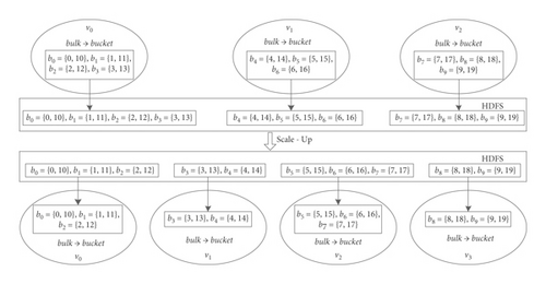
Algorithm 3 shows that, for each operator to be scaled, the stateful data managed by instances are first pushed to the HDFS, and the handler, which records the location and size of the data, is stored in Zookeeper. Second, the supplementary nodes are requested and added to the operator, while the stateful data mapping is revised according to equations (7) and (8), as shown in Figure 5. Finally, each instance requires the data handler to obtain the location of stateful data and pull the data from the HDFS. Moreover, Algorithm 1 is used to regulate the capacity of each edge based on the new structure of the flow network.
-
Algorithm 3: Data redistribution algorithm.
-
Input:
-
Operator to be rescaled: operator[]
-
Resource pool: pool
-
Output:
-
Rescaled flow network: G′
-
Begin
-
foreach O ∈ operator[] do
-
foreach v ∈ O do
-
Send the stateful data of vertex v to the HDFS and the data handler to Zookeeper.
-
end foreach
-
v ← pool.getNode()
-
O.add(v)/∗Enlarge the parallelism of the Operator∗/
-
bucket[]←JobManager.remapping(bucket[],|O|)
-
/∗Remapping stateful data as shown in Figure 5∗/
-
foreach vi ∈ O do
-
Require stateful data from Zookeeper and restore the corresponding stateful data from the HDFS
-
end foreach
-
end foreach
-
flowNetwork_selfLearning(G′)
-
return G′
-
End
By proposing the data redistribution algorithm, the scattered distribution of the data and frequent HDFS access are resolved. Therefore, the overhead of data migration is reduced, and the efficiency of Flink-ER is improved.
3.4. Discussion of Selected Parameter Values
In the capacity detection algorithm (Algorithm 1), parameter η represents the step size of capacity regulation. A value of η that is too high will lead to capacity fluctuation due to overregulation. In contrast, a value of η that is too low will lead to a decrease in the efficiency of the algorithm due to too many rounds of regulation before convergence. Therefore, an accurate and dynamic value of η is the key to achieving efficiency.
In conclusion, parameter η can be calculated dynamically by continuously tracking the latency of the system response time and calculating the deviation between the current and idea value. Therefore, we can obtain the maximum possible capacity if the latency constraint is met.
3.5. Implementation and Deployment of the Strategy
To implement Flink-ER, the basic architecture of the platform should be improved. The architecture of Flink-ER is developed based on the Original Apache Flink.
- (1)
Zookeeper: Zookeeper saves the architecture of the flow network and the metadata of the stateful data at the checkpoint and coordinates among TaskManagers.
- (2)
Capacity detector: this detector, which is a traditional Java thread using Algorithm 2, is responsible for detecting the capacity of the flow network and developing the flow-network model.
- (3)
Rescheduler: the Rescheduler is a traditional Java thread invoking Algorithm 1 that is responsible for optimally dispatching the accumulated data and creating the resource-rescheduling plan.
- (4)
Data migrator: this component, which is a traditional Java thread executed by each TaskManager and uses Algorithm 3, is responsible for pulling the stateful data from the HDFS according to the metadata stored in Zookeeper.
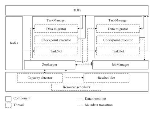
Regarding the data transition, since the controlling information is transformed by Akka [11] between TaskManager and JobManager, TaskManager sends the data handler to JobManager by the Akka actor named AcknowledgeCheckpoint. To implement Flink-ER, the actor named ReportNetwork is developed for the TaskManager to report the current capacity and flow to the JobManager. Moreover, the Rescheduler writes the scheduling plan and other metadata to Zookeeper, while the data migrator reads from it. Therefore, Zookeeper is a crucial coordinator for realizing Flink-ER.
4. Experimental Results and Analysis
To verify the performance improvement of Flink-ER on various kinds of jobs, a practical experiment was set up, and different benchmarks were executed on different platforms. For comparison with related state-of-the-art methods, we realized the core ideology of Sra-Stream [12] on Flink and ran the same benchmarks with Flink-ER for the same experimental setup. The experimental results verify the superiority and evaluate the overhead of Flink-ER compared with those of the Original Flink and Sra-Stream.
4.1. Experimental Setup
To simulate the practical use case, the cluster consisted of 21 personal computers, and the deployment architecture is as shown in Figure 6, in which one node was deployed as JobManager, 6 nodes were deployed as TaskManager, and 4 nodes were deployed in the resource pool as the standby TaskManager for elastic supplementation. Furthermore, 3 nodes were deployed as Hadoop, 3 nodes were deployed as Zookeeper, and 1 node was deployed as the Resource Scheduler. The hardware and software setups are shown in Tables 1 and 2, respectively.
| Item | Value |
|---|---|
| CPU | Intel (R) Core (TM) i7-4790 CPU @ 3.60 GHz |
| RAM | 4 GB DDR3 1600 MHz |
| Disk | 1 TB, 7200 RPM |
| Network | 100 Mb/s |
| Item | Value |
|---|---|
| OS | CentOS 6.5 |
| JDK | jdk1.8.0–181-Linux-x64 |
| Apache Flink | 1.6.0 |
| Apache Hadoop | 2.7.4 |
| Apache Kafka | 2.10–0.8.2.0 |
| Apache Zookeeper | 3.4.10 |
| Redis | 5.0.2 |
Sra-Stream, which is an elastic scheduling strategy for stateful stream processing, is the most closely related contribution to that in this paper. We realized its core ideology and plugged it into Flink as the resource and task scheduling strategy for comparison with Flink-ER. The experimental results and analysis are presented below.
4.2. Experimental Results and Analysis
To compare the performance of Flink-ER with those of Sra-Stream and the Original Flink under different practical application scenarios, four benchmarks, i.e., WordCount, TwitterSentiment, IncrementalLearning, and Streaming-Benchmarks, which come from the source code of Flink (v1.6.0) [13] and a contribution from Intel on GitHub [14], were executed on the three platforms, as they are representative Flink use cases.
In the experiment, the processing latency and data accumulation were gathered through latency tracking in the metrics by periodically sending an HTTP request to the REST API, which is the web UI of Flink, with a 60 s interval. These two indicators directly reflect the performance of the cluster, and the experimental results are as follows.
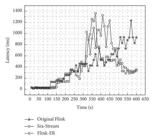
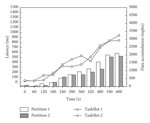
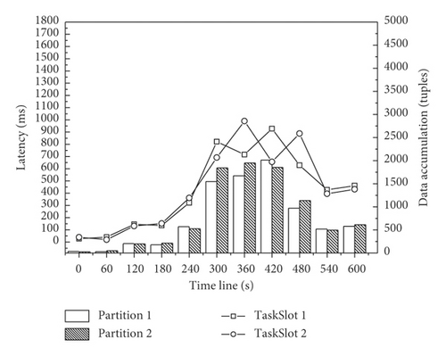
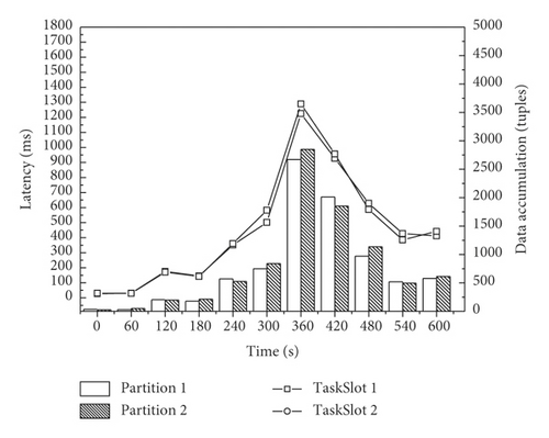
As a CPU-intensive job, WordCount is used to count the frequency of each word that appears in an article. We set the input data as a continuous data flow. The experimental results are presented in Figure 7. The processing latency increased as the data accumulated, which verifies that data accumulation leads to processing latency. Furthermore, without any elastic scheduling strategy, the latency of the Original Flink continued to grow, exceeding 900 ms, which is unacceptable in practice. In contrast, the latency of Flink-ER increased first and then decreased to an acceptable range because Algorithm 2 dispatched accumulated data while supplementing computing resources for 5-6 min. As Figures 7(c) and 7(d) show, during the elastic resource-scheduling process (∼300–480 s), both strategies reduced the processing latency by resource and task rescheduling, but Sra-Stream took longer to schedule resources and was involved in the performance fluctuation. In contrast, Flink-ER took approximately 60 s to schedule tasks and effectively reduced the latency because the data redistribution algorithm reduced the communication overhead during the stateful data migration. After that, both strategies limited the latency within an acceptable range.
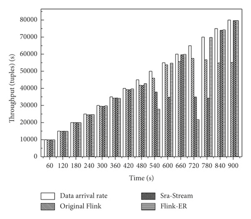
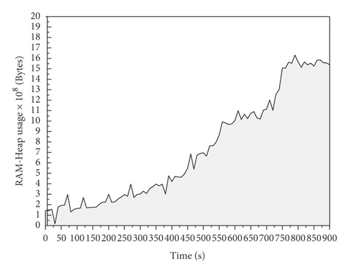
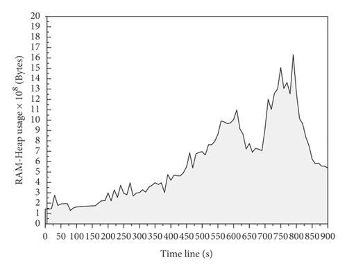
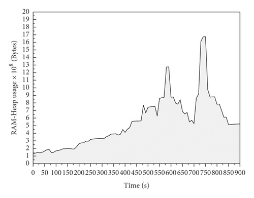
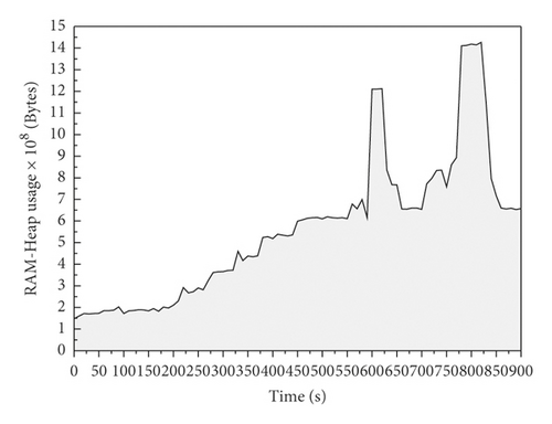
As a memory-intensive job, TwitterSentiment is a standard benchmark used to analyze user sentiment through tweets, reflecting the data accumulation by memory usage. Therefore, the continuous data flow of user tweets on Twitter in JSON format is set as the input data source. Since each vertex retains complicated stateful data during the execution of TwitterSentiment, the overhead of data migration by Algorithm 3 is verified. Therefore, Figure 8(a) illustrates that, with the increase in input load, the throughput of the cluster decreases due to a lack of computing resources, while both elastic resource scheduling strategies promoted throughput by optimizing the load distribution and supplementing resources, which contributed a significant improvement. In addition, Figures 8(c) and 8(d) illustrate that memory utilization is reduced in both strategies. However, Sra-Stream required more time for stateful data migration and exhibited scheduling fluctuation. Flink-ER required less time for scheduling but had higher memory utilization for data accumulation during the stateful data restore process from the HDFS. In general, the memory overhead for task scheduling in Flink-ER is acceptable in practice.
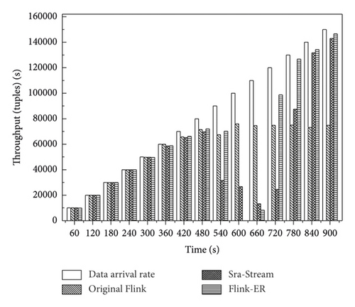
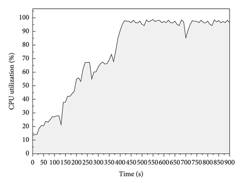
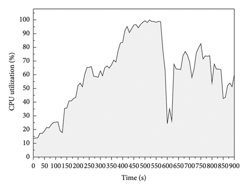
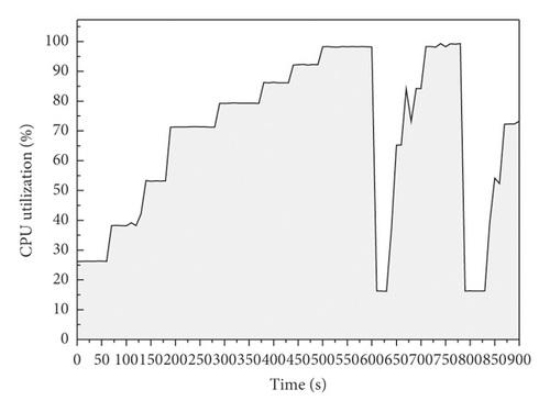
As a CPU-intensive job, IncrementalLearning is a complicated iterative computation on a large-scale matrix in which the CPU is the typical scarce resource during execution. Figure 9(a) illustrates that the bottleneck of the Original Flink limited less than 80000 tuples/s, while both strategies provided significant improvement with acceptable overhead. Figures 9(b)–9(d) show the CPU utilization of one TaskManager in the cluster. With the increase in processing load, the CPU utilization approached 100%, which means that the lack of CPU resources limited the throughput and performance of the cluster. In contrast, both scheduling strategies decreased CPU utilization by supplying more computing resources, enlarging the parallelism of CPU-intensive operators (iterative computation in this job) and distributing the processing load. However, the imperfections of the two strategies are different. Sra-Stream showed fluctuations in the system response latency and resource utilization, while Flink-ER had a short processing break (approximately 3 s) for stateful data migration; the job was then restored to normal execution with better performance. Future research will focus on shortening or reducing breaks. Moreover, since all the systems executed the same learning benchmark during the experiment, their learning accuracies are exactly the same, but their executing efficiencies and performance results are different.
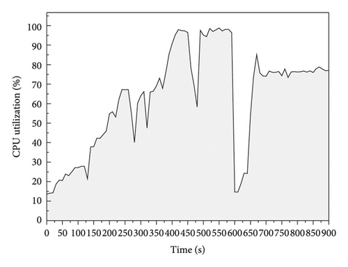
Streaming-Benchmarks is used for advertisement analysis and was contributed by Yahoo on GitHub [15]; it is a typical use case in data analysis for mobile devices. As Figure 10 illustrates, because of the high input load, complicated computation, and large-scale stateful data, the execution of the benchmark occupied both the CPU and memory resources of the TaskManager nodes. However, the Original Flink is not capable of processing data regarding the arrival rate on time, which results in data accumulation and latency increase. Therefore, the cluster executed both resource scheduling strategies over 600 s and 780 s while improving the performance by supplementing resources. The decrease in data accumulation and processing latency verified that resource rescheduling effectively improves the performance of a cluster by supplementing the resource and rescheduling tasks. In addition, before rescheduling, Flink-ER provided a higher throughput by optimally dispatching accumulated data. During rescheduling, Flink-ER reduced the overhead through efficient stateful data management and migration. After rescheduling, the cluster was likely to stabilize faster. Therefore, compared with Original Flink and Sra-Stream, Flink-ER is more suitable for practical application scenarios with complicated stateful data and is more applicable to data analysis in mobile information systems with complicated computing.
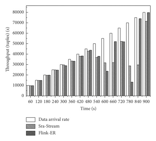
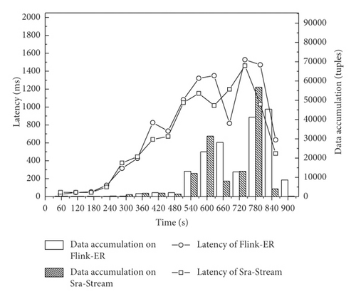
In conclusion, by dynamically rescheduling resources and efficiently migrating stateful data, Flink-ER promotes cluster throughput via latency constraints. Compared with Original Flink, Flink-ER improves the job execution efficiency by proposing an elastic resource-rescheduling strategy. Compared with Sra-Stream, Flink-ER reduces the overhead of rescheduling by proposing an efficient stateful data management and migrating strategy. The specific conclusions of the experiment are presented in Table 3.
| DSPS | Scheduling strategy | Advantage | Disadvantage | Applicable scenario |
|---|---|---|---|---|
| Flink | Default scheduling strategy | Exactly once processing | Performance bottleneck | Constant and invariable processing load |
| Sra-stream [12] | First-fit and latency-sensitive runtime-aware-based scheduling | Stateful data scheduling | Scheduling performance fluctuation | Little stateful data |
| Flink-ER | Flow-network-based dynamic scheduling | Accurate breaking of bottleneck with lower overhead | Instantaneous break out | Large-scale stateful data |
4.3. Overhead Evaluation
Since the migration of stateful data involves transition overhead that might affect the performance of the cluster, the data transmission during the checkpoint and restore process was evaluated. Streaming-Benchmarks and TwitterSentiment are streaming jobs with complicated stateful data; hence, they were used to evaluate the transition overhead, while the network transition monitoring operations for Linux, i.e., iftop and tcpdump, were used to monitor transmission among the nodes. The captured data are presented in Figure 11.
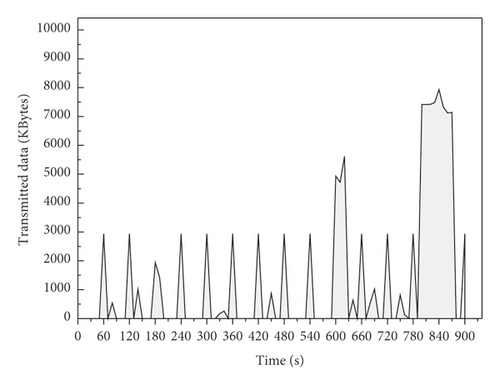
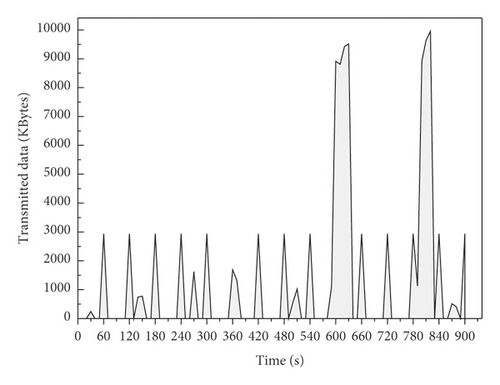
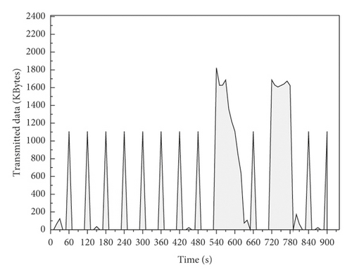
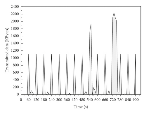
Figure 11 clearly shows that the checkpoint is involved in a small periodic transition because of the execution of the incremental checkpoint. Regarding the restoration process, the quantity of restored data was the same in both platforms, but Flink-ER took less time to restore data because stateful data are stored in the HDFS centralized in the data management system by a bucket. In addition, the frequency of HDFS access is significantly reduced by the data redistribution algorithm. In conclusion, Flink-ER efficiently reduced the overhead of data transition compared to original Flink.
4.4. Analysis of the Task Break Out
According to the experimental results, since existing work on elastic resource scheduling suffers from the problem of instantaneous break out, Flink-ER effectively shortens the break by about half due to the load migration process. The execution of the data processing thread will modify the stateful data. However, it is important that the stateful data remain consistent during migration among nodes, as consistency is crucial for ensuring the accuracy. Therefore, the data processing thread in each node should be paused during stateful data and task migration to maintain the consistency of stateful data. However, the task break out still affects the performance of the continuous mobile stream data processing within an acceptable range.
Therefore, completely eliminating the break out remains a goal for future work. To realize online elastic resource scheduling without any break out, the stateful data of each node should be migrated when the data processing thread is running while changes in stateful data should be merged. By considering the characteristics of the checkpoint mechanism in Flink, future work will focus on implementing both task scheduling and data processing and merging stateful data. By proposing an online stateful data and task migration algorithm, the problem of task break out will be resolved, and the performance of elastic resource scheduling will be improved.
5. Related Work
To address the performance decline DSPSs face with fluctuating data streams with different arrival rates, great efforts have been made by researchers to improve the performances of various stream processing engines. Three main approaches are used to address the problem: (1) improve the performance of clusters by optimizing the task scheduling strategy; (2) improve the job execution efficiency by reducing the communication overhead among computing nodes; and (3) improve the scalability of clusters by proposing an elastic resource-rescheduling strategy. The strengths and weaknesses of these methodologies as well as representative contributions are summarized below.
First, optimizing the task scheduling strategy is the most representative traditional technique for improving the performance of DSPSs while guaranteeing the latency constraint. Sun et al. [16, 17] propose different task scheduling strategies on a directed acyclic graph (DAG) of the topology, which achieve outstanding performance in terms of reducing both processing latency and energy consumption. Additionally, previous studies [18–21] formulate a variety of task-scheduling methods by analyzing various characteristics of the topology. In terms of latency, throughput, and resource utilization, they create a task rescheduling plan and improve the topology structure of the job, which is an effective methodology for improving the performance and efficiency of the data stream processing system. However, the task scheduling strategy fails to identify the performance bottleneck or resolve the performance decline when the data arrival rate fluctuates over time. Second, reducing the communication overhead is a popular task scheduling strategy in which tasks are scheduled according to communication performance metrics. Eskandari et al. [22] implement T3-Scheduler for Storm, which can efficiently identify the tasks that communicate with each other and assign them to the same node. Silva et al. [23] propose a methodology for monitoring communication metrics on the edges of DAGs as the training set of reinforcement learning to reconfigure the topology. Moreover, previous studies [24–26] propose different task scheduling strategies for minimizing communication overhead and reducing processing latency. Since data transition contributes the most overhead to the cluster, they reschedule tasks with the most data transitions to the same computing node to reduce communication overhead across nodes, which is an effective method for improving the efficiency of data transition and processing. However, the communication overhead may change drastically with changes in the topology structure and processing load. Therefore, scheduling strategies based on communication metrics are usually not able to respond on time.
In comparison with the two methodologies above, the elastic resource rescheduling strategy is an effective way to overcome the performance bottleneck when handing a continuously fluctuating data stream [27]. Jonathan et al. [28] discuss the trade-off between the reconfiguration of query executions and the adaptation of existing reconfiguration techniques. They find that the best adaptation technique depends on the network conditions, type of query, and optimization metrics. Hidalgo et al. [29] propose a methodology for measuring the elasticity and scalability of distributed stream processing systems, which is very useful for benchmarking the performance of DSPSs when the data arrival rate fluctuates over time. Russo et al. [30, 31] propose different elastic data stream scheduling strategies with a reinforcement learning approach that autorescales the DSPSs by using self-learning algorithms and the performance metrics of the cluster. The integration of machine learning in elastic resource scheduling strategies in DSPSs is promising but still not applicable to industry. Meanwhile, previous studies [32–37] propose a variety of elastic resource dynamic scheduling strategies from the perspectives of self-adaptation, resource constraints, and topology features, which are suitable for different application scenarios. By taking performance metrics and architectural characteristics of specific platforms into consideration, they propose different elastic resource scheduling strategies for disrupting the performance bottleneck. However, some of the above strategies may involve scheduling overhead, and others cannot be applied to Flink.
- (1)
To execute elastic resource scheduling, tasks and stateful data should be migrated to computing nodes, which requires significant communication overhead, and the long instantaneous break out may exceed the acceptable range [41]
- (2)
Existing online data migrating and task scheduling strategies may produce results with performance fluctuations and declining cluster stability, which are not appropriate for industry application
- (3)
As a resource optimizing method, the existing scheduling strategy requires excessive computing resources, which affect the performance of data processing and is not acceptable in resource-intensive application scenarios
- (1)
Existing studies change the scale and operator parallelism without considering the utilization of existing resources. This paper makes full use of existing computing resources by improving the throughput before executing elastic resource scheduling.
- (2)
Existing studies do not take the stateful data [36] into consideration during task scheduling. This paper proposed a stateful data management model and stateful data migration algorithm that efficiently reduced communication overhead during task scheduling.
- (3)
In general, the existing studies propose resource scheduling strategies based on resource utilization (including CPU, RAM, and network bandwidth). This paper comprehensively considers the processing latency and throughput of the cluster to directly and effectively disrupt the performance bottleneck.
6. Conclusions and Future Work
As the most popular DSPS, Apache Flink has been widely applied for processing the mobile information data stream. However, the lack of a resource-rescheduling strategy results in a decline in performance and limits the further development of the platform. Therefore, Flink with an elastic resource scheduling strategy (Flink-ER) is proposed in this paper. The experimental results show that the strategy efficiently promotes the throughput of the cluster and reduces the communication overhead of stateful data migration under latency constraints by optimizing the data distribution strategy, elastically rescheduling the resources and effectively reducing the data migration overhead.
- (1)
To solve the problem of instantaneous break out, an online stateful data and task migration algorithm should be designed and implemented
- (2)
To reduce dependence on outside components such as Zookeeper, the Flink master should be improved to independently carry out elastic resource scheduling
- (3)
To widely apply a data stream processing system in the mobile information processing area, more relevant problems should be resolved in more application scenarios
Conflicts of Interest
The authors declare that they have no conflicts of interest.
Acknowledgments
This research was supported by the National Natural Science Foundation of China (Grant nos. 61862060, 61462079, and 61562086), Natural Science Foundation of Xinjiang Uygur Autonomous Region of China (2017D01A20), Educational Research Program of Xinjiang Uygur Autonomous Region of China (XJEDU2016S106), and Doctoral Innovation Program of Xinjiang University (Grant no. XJUBSCX-201902).
Open Research
Data Availability
The data used to support the findings of this study are available from the corresponding author upon request.


