
Continuum Robots for Manipulation Applications: A Survey
Abstract
This paper presents a literature survey documenting the evolution of continuum robots over the past two decades (1999–present). Attention is paid to bioinspired soft robots with respect to the following three design parameters: structure, materials, and actuation. Using this three-faced prism, we identify the uniqueness and novelty of robots that have hitherto not been publicly disclosed. The motivation for this study comes from the fact that continuum soft robots can make inroads in industrial manufacturing, and their adoption will be accelerated if their key advantages over counterparts with rigid links are clear. Four different taxonomies of continuum robots are included in this study, enabling researchers to quickly identify robots of relevance to their studies. The kinematics and dynamics of these robots are not covered, nor is their application in surgical manipulation.
1. Introduction
1.1. Why Continuum Robots?
In the manufacturing industry, robots have steadily gained importance in assembly-line operations due to their compelling value proposition: reduced cycle-time and increased accuracy, along with a skillset [1]. A typical industrial robot is floor-mounted for safety and consists of discrete rigid links that are actuated for gross movement of the end effector and of a task-appropriate end effector with fine motor control. Sophisticated control software operates individual robots or coordinates multiple robots in order to maximize their value in a specific industrial operation [2].
Against this backdrop, continuum robots are emerging as a novel concept, at least in research, with the potential to be used across a wide range of industrial applications [3]. Continuum robots are hyperflexible electromechanical structures with infinite degrees of freedom which provide them with the ability to maneuver complex curvilinear pathways (a survey on continuum manipulators [4]). A key advantage of continuum robots over those with rigid links is that, due to their considerably lower weight for the same maximum output force, they can be ceiling-mounted as opposed to floor-mounted. This advantage significantly increases their safety when they are used in joint operations with humans on the factory floor [5]. On the flip side, continuum robots are inherently more nonlinear and thereby harder to control than their discrete rigid-link counterparts, thereby presenting a barrier to adoption in the industry [6].
Continuum robots have increased flexibility, and thereby dexterity, compared to their rigid-link counterparts (the importance of continuum robots [7]). Figure 1 from [8] illustrates the essential difference between a discrete, a serpentine, and a continuous-link structure. It is clear from this figure that continuum structures have more degrees of freedom to move, and thereby, they are able to move more precisely along the shape of an object. In addition, their ends can position themselves in many more 3D facing directions compared to rigid-link structures. Researchers are developing continuum robots for a variety of navigation [9] and exploration [10], manufacturing and assembly [11], and medical and surgical applications [12].

1.2. Bioinspired Robots
When it comes to continuous actuated structures, biological systems from nature (Figure 1) have some compelling characteristics worth mimicking: symmetric and optimized design, evolution-enabled uniqueness for the task at hand, and, finally, energy-efficient kinematics and dynamics for survival (survey of bioinspiration [13]). Researchers have been inspired by the animal and plant kingdoms when it comes to designing their continuum robots, and Table 1 presents our first taxonomy, namely, the bioinspiration behind various robots surveyed herein: our survey includes multiple references to Walker’s research group publications—they are not only one of the earliest to investigate biological structures for continuum robots, starting with the elephant’s trunk [27], but they have also had the largest footprint of any research group, the left column of Table 1 [14–31].


1.3. Survey Organization
Continuously articulated structures in the bio-kingdom are made up of muscles, tendons, fibers, and joints. One of the three focus areas of this paper is a survey and taxonomy of continuum robots from the standpoint of their mechanical structure (Section 2). The influence of the bio-kingdom on continuum robots is so complete that an overwhelming majority of continuum robots are made of soft materials that allow these robots to have the required flexibility. The second focus area of this paper is a survey and taxonomy of continuum (soft) robots in terms of materials (Section 2). Continuous robotics use hydraulic, pneumatic, and electrical actuators. Our final taxonomy of continuum robots is based on a survey of the types of actuators used to achieve their motion (Section 4). The paper concludes with some broad remarks regarding the robots surveyed and some observations on where the field is headed (Section 5). More than two hundred references are cited herein, and the citation details are at the end of this paper (References). We reiterate that the kinematics and dynamics of these robots, including sensors and control, as well as their application in various surgical applications, are beyond the scope of this paper. For those topics, we refer to the following excellent surveys: [12, 184, 185].
2. Structure and Material
The taxonomy and evolution, along with the materials used, of continuum robot development inspired by biostructures are discussed in this section.
2.1. Structure
The structure of the continuum robot used for manipulation is broadly classified into a single or multisegment robot in the early phases of research [186]. In order to enhance the functionality, multiple discs are inputted as a backbone for these robots in order to mimic a continuum structure, examples of which are shown in Table 2. Every continuum robot developed falls into the category of bioinspiration mentioned in Table 1, and the description in Table 2 provides a brief outline of the models developed.
| Robot structure | Description | Application | Advantage | References (examples) |
|---|---|---|---|---|
| Single segment | Robot body consists of a single backbone-like structure with limited constant curvature freedom of motion. | Cleaning | Simple structure | Elephant: [15] |
| Human arm: [156] | ||||
| Octopus: [76] | ||||
| Vine: [179] | ||||
| Multisegment | Robot body consists of multiple segments, each with the freedom to move as a single element structure, but independent of other elements. | Inspection | Connected control | Elephant: [14] |
| Human arm: [51] | ||||
| Vine: [173] | ||||
| Tongue and tail: [183] | ||||
| Snake: [70] | ||||
| Single segment-multidisc | The robot body is composed of multiple discs of the same or varying radii arranged equidistant from each other, along with a backbone structure that is a single segment. | Medical surgery | Maneuverability | Elephant: [28] |
| Mammalian spine: [35] | ||||
| Snake: [32] | ||||
| Tentacle: [87] | ||||
| Tongue and tail: [182] | ||||
| Vine: [166] | ||||
| Multi segment-multidisc | The robot body is composed of multiple discs of the same or varying radii arranged equidistant from each other, along with a backbone structure that is of multiple segments. | Mobility | Multipurpose | Elephant: [24] |
| Mammalian spine: [42] | ||||
| Snake: [63] | ||||
| Tentacle: [91] | ||||
| Human arm: [157] | ||||
| Vine: [180] | ||||
| Continuous structure | Robot body consists of multiple fibers braided together. The fiber ends are connected to cables that can be individually wound up/down from a pulley. | Manipulation | Flexibility | Snake: [68] |
| Octopus: [72] | ||||
| Tentacle: [90] | ||||
| Biological vine: [161] | ||||
| Human arm: [149] | ||||
| Plant: [181] |
In the early phases of research [14–20], known as first-generation continuum robots, the elephant trunk models [187] were constructed with a maximum of three segments with pneumatic actuation. Jones and Walker, along with researchers at Clemson University, had developed two robots, OctArm [14] and Air-Octor [16], with a single segment mimicking a trunk (Figure 2(a)). The soft gripper developed in the shape of a cone [18] is an example of the single-segmented robot. The soft manipulator [17] is bisegmented, and the granular robots [20] are the additional models with dual and triple segments (Figure 2(b)). As an advancement, the research on the second-generation robots consists of trunks with a backbone and multiple discs, with the increased complexity of actuation and manipulation. These trunks consist of multiple segments with dual actuation, i.e., electric motor and pneumatic [21–28]. In the current research scenario, the third-generation continuum robot, which is known as the bionic handling assistant (BHA) model developed by Festo [29–31], has entered the production environment. This is an advanced prototype that is constructed using the concepts of lightweight design and possesses the capability to operate with increased flexibility. This model consists of three segments with variable curvatures supported by tendons and with a weight of 1.8 kg. The structure and components of the BHA are shown in Figure 2(c), along with the three-fingered end effectors to grasp the objects.


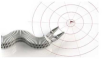
Continuum models inspired by the spine of the mammal [32–55] and snake [56–71] are the most common examples of the multidisc biomodels with single or multiple segments that consist of a structured alignment of discs, as shown in Figure 3(a). Spine structures can possess only bending movements with limited angular constraints and with a fixed base, and snakes belong to the class of reptiles that have the capability to elongate their bodies without limbs to grasp or manipulate objects with precision in a confined space. The single-segment-multidisc models, spine [32–42] and snake [56–62], are generally made up of circular metal structures equidistantly placed along the backbone. The discs are magnetically polarized so that the distance between the discs remains constant and can take up the shape of constant curvature to achieve the hemispherical surface of the end effector. These discs are either made up of steel or hard polyamide material. The multisegmented models of the spine [43–55] are aligned with metal intervertebral discs aligned at a constant distance that provide nonlinear damping characteristics, and snake [63–67] is constructed with cylindrical tubes connected with joints with rotational and translational degrees of freedom and mostly used for inspection through holes, as shown in Figure 3(b). To reach the model of a continuum structure, snake models [68–71] are developed that are made up of braided or shape memory alloy materials and consist of dual actuation, i.e., are cable or pneumatic driven.


Octopus- and tentacle-inspired [84–131] models are mostly single-segmented examples. Octopus is a class of cephalopods whose structure is symmetric along the axis bisecting its two eyes, whereas tentacle is a long-elongated organ (example of tentacle inspired robot [121]) present in many invertebrates that usually occurs in pairs. The legs of the octopus have the unique capability to perform locomotion and manipulation [188], and tentacles are tiny thread-like structures that are used for grasping and feeding along with sensory reception, which proves the easy choice for robotics enthusiasts to develop continuum structures that are single-segmented (Figure 4(a)). Laschi et al. [72–76] are one of the early researchers who developed continuum robot models built with longitudinal and transverse actuators using silicone and braided fiber as materials (Figure 3(b)). To develop a realistic case scenario, Guglielmino et al. [78] had obtained consent with respect to EU regulations to perform morphometric analysis on several anaesthetized octopuses with the support of a marine biologist. This experiment provided detailed information regarding the structure of octopus limbs, which assisted in developing prototypes [79–83] using shape memory alloys (current sensitive) and fluid actuators mimicking the animal behavior.


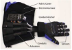
The human arm is the most complex biomodel, and researchers have developed models that augment safety in manipulation applications with respect to physical human interaction. All such robot structures can be categorized into two models, i.e., multifingered hand robots (Figure 5) and multijoint extendable arms (Table 3). All the multifingered hand robots [132–146] were developed to have a similar structure, with a metal or plastic base and fingers made up of hardened polyamide material. The human arm robots [147–159, 189] are designed with multijoints and a unique end effector and are categorized based on the application perspective, as shown in Table 3.


|
|
|
|
|
|
|
|
|
|
|
|


 0
0 1
1 2
2 3
3 4
4
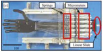
All the biomodels discussed in the previous sections are animal-inspired robots. In this section, the continuum robots that are vine and plant inspired are explored. The hyperflexible manipulator (HFM) developed by Suzuki et al. [160] is one of the best examples of vine inspired, consisting of multiple underactuated links and nonelastic passive joints resembling a rope used for better casting and winding along the object. The primary application of vine-inspired robots is in the field of space and planetary exploration. Scientists at NASA, Mehling et al. [161] and Tonapi et al. [163], developed a tendril robot (Figure 6(a)) and a robotic manipulator for minimally invasive inspection along with manipulation for space operations [160–170]. The tendril robot consists of three subsystems with nine motors of actuation, body mechanism, and avionics, as shown in Figure 6(a) [161]. In order to utilize the capability of extending their segments longitudinally, the class of continuum robots [175–181] inspired by biological plants was developed. Their structure is pneumatically actuated [181], which controls the longitudinal height and is made up of a polyamide structure that is widely used in deploying antennas [177–179] or in operations that require a periscope [175, 180]. To enhance the application areas of vine robots, researchers found advantages of using these structures [171–174] in further applications, including autonomous refueling, exploration [174], water spraying [171], aircraft fueling [173], body inspection [170, 176], and engine repair [172], as shown in Figure 6(b).


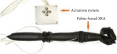
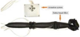
The final categorization of the continuum robots is the structure inspired by the tail and chameleon tongue of an animal. The chameleon tongue-inspired robot (Figure 7(b)) [183] consists of a mechanism that can accommodate the principle of elastic energy storage and release, which can elongate to 1.5 times its body length and can exert a force of 500 m/s2. The tail (Figure 7(a)) [182] on the structures has very few engineering applications, which are envisioned for use on board a mobile robot to provide a means separate from the locomotion mechanism (e.g., legs or wheels) to generate external forces and moments to stabilize and/or maneuver the robot.


2.2. Material
The material of choice for bioinspired continuum robots is polyamide—a polymerized molecular chain made of nylon braided blend or carbon amalgamation (e.g., borax and vinyl alcohol) whose strength, elasticity, and flexibility can be customized per the application. Other materials used in construction of continuum robots are silicone, nitinol, aluminum, braided fabrics, and shape memory alloys. Tables 4 and 5 provide a taxonomy of various materials used in the construction of continuum robots.
| Polyamide material | Advantages | Robots (examples) |
|---|---|---|
| Polycarbonate | Durability, high impact, and low scratch resistance | Exploration robot [174] |
| Polyamide-rubber amalgamation | Contraction and elongation | Artificial muscles [190] |
| Polyurethane | Lightweight design, temperature resistance | Engine repair robot [172] |
| Polyethene | Elasticity and bending, low cost | Periscope and antenna robot [178] |
| Polyamide-carbon amalgamation | Highly flexible, oxidation and corrosion resistance, electrical conductivity, resistance, and elasticity | Bionic trunk [29–31] |
| Other materials | Advantages | Robots (examples) |
|---|---|---|
| Silicone | Abundantly available with lost cost and provides extraneous flexibility; resistant to abrasion, acidic, and basic ambience | Octopus arm [72, 73] |
| Nitinol | Inert material with maximum nickel composition, very dexterous, and manipulative | Vine-inspired robot [163], spine robot [34] |
| Aluminum | Low cost and lightweight | Hybrid robots—multidisc [191] |
| Braided surface | High strength and lightweight | Dual-segmented [34] elephant trunk [17] |
| Shape memory alloy | Strong and corrosion resistance | Octopus limbs [79–83], elephant trunk [21, 23] |
3. Force Actuator
Force actuator refers to the component of a continuum robot that drives its physical movement. The most common actuators used within continuum robots are either pneumatic or electrical motors. Although not as common, other actuators such as hydraulic, twisted polymer, thermal, or magnetic are also used in fewer applications.
3.1. Pneumatic Actuator
Pneumatic actuators [46, 190–220] are the most commonly used kind in continuum robots because they are less complex and are low cost. The drive is produced by forced air injected or withdrawn from the body of the continuum structure (Table 6). These were first developed under the name of McKibben actuators arranged symmetrically along the central axis of the robot’s body with flexible pairs on opposite sides pressurized by one solenoid valve, which controls the volume and direction of the airflow using a pressure sensor. The dissection of the artificial pneumatic muscle actuator (PMA), along with the body modeled using fiber [209] or braided [206] material, is shown in Figure 8. PMA provides a good balance of actuation performance and power-to-weight ratio, the description of which is significantly explained in the survey [221]. Further examples of continuum robotic structures developed using the PMA are shown in [46, 190, 191, 212–220].
| PMA | Description | Usage | Advantage |
|---|---|---|---|
| Braided material [192–207] | Produced using weaving and knitting methodology. | Mostly used in the manufacturing industry and lightweight machine operations. | This structure possesses the useful property of elongation and compression with respect to the input air pressure. |
| Fiber material [208–211] | Two kinds of fibers are currently used in the industry, depending on the application, produced by plants, animals, and geological processes. | Used in every technical engineering application. Suitable for heavyweight operation. | Possesses excellent twisting and longitudinal strength. |

3.2. Electrical Motors
The tendon-driven continuum manipulators are the first structures developed with bending segments of adjustable length. These structures assist the body to generate curves with variable curvature radii, which augments the efficiency of grasping. Researchers examined the properties of tentacle-like continuum robots and arranged tendons in pairs that are actuated by motors. Almost every structure with a built-in tendon is actuated by electric motors (direct current, servo, or stepper motors) (Table 7).
3.3. Drive Mechanisms
In general, the articles referenced in this paper do not discuss the underlying drive mechanism in detail as they focus on the novelty of their continuum robots with respect to design elements and mobility. The drive mechanism of the continuum robot is generally categorized into either tendon or nontendon driven (Figure 9). These mechanisms have common functionality of manipulation along with defining the body shape and the end-effector position of the robot (Table 8).


| Drive mechanism | Force actuation | Advantages | Disadvantages | Material |
|---|---|---|---|---|
| Tendon driven [32–71] | Electric or pneumatic | Simple calculation and low error in estimating the end-effector position | Complex body structure | Polyamide structure |
| Nontendon driven [192–211] | Pneumatic (PMA) | Simple body structure to contract and elongate | Complex calculation and high error in estimating the end-effector position | Braided and fiber |
4. Additional Design Elements
In this section, we briefly outline some additional information with respect to dual actuation and sensors. Some of the primary continuum robotic structures have a built-in dual actuator (pneumatic and electrical motor), which provides the additional advantage of increased actuation capability and reduced errors in movement, i.e., manipulating the end effector to the desired location, obtaining the desired shape of the robot with increased degrees of freedom, and so on. The bionic arm is the latest example that utilizes the advantage of the dual actuator mechanism. One of the main challenges for developing continuum robots for manipulation is estimating the required amount of actuation, the shape of the robot, and the position of the end effector at an instant in real time. The information regarding these parameters can be obtained using various sensors inbuilt in the system, which can hugely assist in the robotic control to achieve the defined task. Although the control techniques are out of the scope of this survey, we briefly mention different kinds of sensors [222–240] used in the current research scenario. Sensors in the field of soft robots are broadly classified into three categories based on their application, i.e., force actuation, shape, and end-effector position estimation. Among the various sensors adopted, the optical sensor proves the best because of its lower error tolerance and its ability to be utilized for the dual purpose of shape and end-effector position estimation (Table 9).
| Application | Sensor type | Description |
|---|---|---|
| Force actuation | Pressure sensor | The pressure sensor provides the feedback of the air pressure applied by the pneumatic actuator [226]. |
| Torque sensor | The torque output by the electrical motor is measured by the torque sensor [222]. | |
| Robot body shape estimation | Potentiometer | Potentiometers consist of sliding or rotating contacts, which are installed to know the length of each segment of the continuum robot based on the change in the voltage [224]. |
| Image camera | An image camera consists of a high-resolution lens with a maximum frame rate to estimate the shape in real time using image processing and machine vision techniques. Common examples include Dalsa camera, Kinect camera, XCD X710 digital camera, AK 4, and AK7 [229, 230, 232–234]. | |
| Resistor shape sensor | The resistive sensor is sensitive to twisting or elongation and changes its resistance proportional to the deflection [237, 240]. | |
| Fiber Bragg gratings | FBG are similar to optical sensors. These sensors are mostly used to obtain the curvature of the robot body in the static and dynamic mode by obtaining the strain information at different locations along the structure [223, 227]. | |
| Dielectric elastomer | This sensor is embedded into the actuators with distributed actuation points that could cover soft bodies. It is highly flexible and can be adaptable to soft structures to obtain information regarding surface deflections. The examples used in robotics include DEAs, VHB 4910 [236, 238]. | |
| Magnetoresistive sensor | The magnetoresistive sensor is mostly used to detect any kind of geometrical deflection or thermal sensitivity and provides an output based on the desired parameters, e.g., contraction of a bundled actuator [225]. | |
| End-effector position estimation | 3D electromagnetic sensor | These sensors are generic sensors that are electromagnetic wave emitters and are installed onto the shape of the robot and emit the signals in regular intervals captured by receivers [192]. |
| Infrared sensor | An infrared sensor is less accurate when compared to other electromagnetic sensors because of temperature sensitivity. It emits radiation to estimate the relative coordinate position, e.g., MicroScribe MX [180]. | |
| Optical sensor | The optical sensor is the most accurate sensor for estimating the coordinate positions of any robotic component. It is used for modulating the intensity of light from the specific position to estimate the relative distance, which can also be used to estimate the shape of the robot, e.g., Micron Tracker SX60 [235]. | |
| Laser sensor | The laser sensor is a type of optical sensor that is capable of projecting electromagnetic radiation to a specific point on the end effector to obtain the relative position coordinates, e.g., FARO Edge laser [34]. |
5. Conclusion
Innovation and creativity are two of the essential ingredients in the evolution of robotics and automation, which started a century ago. Developing continuum robots that mimic biologically inspired species began more recently—two decades ago. Here, the natural design elements present in humans, animals, birds, plants, etc. provide a template for scientific progress. As a result, continuum bioinspired robots have been investigated for numerous applications.
In this literature survey, we covered numerous bioinspired continuum robot models that have been developed and provided a framework for examining them, namely, bioinspiration, mechanical design, construction material, and force actuation. The progress made in continuum robotics is very compelling and provides a great foundation to tackle the major challenges required for their use in manufacturing—low cost, reduced cycle-time, and safe human interaction.
Conflicts of Interest
The authors declare that they have no conflicts of interest.
Acknowledgments
The authors thank Prof. Dr. Alireza Mohammadi, University of Michigan, USA, for participating in initial discussions and William J. Clifford, General Motors Inc., Warren Technical Center, Michigan, USA, for supporting this research.