Volume 2019, Issue 1 9854187
Research Article
Open Access

Coupled Responses in a Partially Liquid-Filled Cylindrical Tank with the Single Flexible Baffle under Pitching Excitations

Jiadong Wang

Corresponding Author

Jiadong Wang

Faculty of Civil Engineering & Mechanics, Jiangsu University, Zhenjiang, China ujs.edu.cn

Search for more papers by this author
Jinxing Liu

Jinxing Liu

Faculty of Civil Engineering & Mechanics, Jiangsu University, Zhenjiang, China ujs.edu.cn

Search for more papers by this author
Dan Wang

Dan Wang

Army Engineering University of PLA, Nanjing, China ust.com.cn

Search for more papers by this author
First published: 2019
Citations: 5
Academic Editor: Emiliano Mucchi

Abstract

Antisloshing baffles are widely used in many engineering fields, including aerospace, ocean engineering, and nuclear engineering. The semianalytical scheme is proposed to explore the effect of the single flexible baffle on the coupled responses in the rigid cylindrical tank partially filled with ideal liquid undergoing the pitching excitation. The function series for the velocity potential, the dynamic deflection of the flexible baffle, and the surface wave height are given by introducing the time-dependent generalized coordinates. The Stokes–Joukowski potentials which are contained in the liquid velocity potential can be solved analytically. According to the dynamic and kinematic equations for the free surface and the coupled vibration equation for the flexible baffle, the coupled dynamic response equations are obtained. The additional damping terms are introduced to account for the sloshing damping. The semianalytical method is validated by the comparison study with the numerical results. Parameter studies are conducted to investigate the effects of the parameters of the flexible baffle on the coupled responses of the system.

1. Introduction

The liquid sloshing in moving tanks partially filled with liquid is of great practical importance in many engineering applications, such as LNG (liquefied natural gas) tanks undergoing seismic excitation and fuel tanks in moving spacecrafts. Baffles are usually used to control the liquid sloshing.

The experimental investigations for the effectiveness of the antisloshing baffle in various tanks were reported in several literatures. Goudarzi et al. [1] carried out experiments to investigate the sloshing damping which was provided by horizontal and vertical baffles installed in the rectangular tank, in which the liquid has the free surface. Xue et al. [2] designed the liquid sloshing experimental rig, which is driven by the wavemaker, to investigate the free surface fluctuation and pressure distribution in the rectangular tank with the perforated baffle. Hosseinzadeh et al. [3] conducted shaking table experiments to examine the effect of the antisloshing baffle on the surface wave height of the liquid in the cylindrical tank. Xue et al. [4] conducted experimental studies on the effects of different baffles on the hydrodynamic pressure in the rectangular tank partially filled with liquid undergoing the lateral excitations. Yu et al. [5] studied experimentally the effectiveness of two floating plates in reducing the liquid sloshing in the membrane-type LNG tank under pitching excitations. Chu et al. [6] performed experimental investigation on the sloshing phenomenon in the rectangular liquid-filled tank with multiple bottom-mounted baffles undergoing lateral excitation. Experimental results reveal that the antisloshing baffle can help in effectively reducing the surface wave height and change hydrodynamic pressure distribution of the tank wall.

The motion of the free surface of the liquid in various tanks which are equipped with the antisloshing baffle has been widely simulated using the numerical methods. Xue and Lin [7] developed the three-dimensional numerical model NEWTANK to investigate the viscous liquid sloshing in the rectangular tank with internal baffles of different shapes and arrangements. Akyildiz [8] studied the effect of the vertical baffle on the nonlinear liquid sloshing in the two-dimensional rectangular tank by the numerical algorithm based on the volume of the fluid technique. The results showed that, as the baffle height increases, the intensity of the vortex generated at the sharp edge of the baffle became weaker. Using the modal analysis and the BEM (boundary element method), Noorian et al. [9] developed the reduced order model to explore the interactions of the liquid and the flexible structure in the baffled tanks. It was concluded that the baffles with a large flexibility has a significant effect on the coupled dynamics characteristics. Koh et al. [10] examined the effectiveness of the constrained floating baffle (CFB) in reducing the surface wave height in the tank. Based on the noninertial reference system, Lu et al. [11] investigated the sloshing of the viscous liquid in baffled rectangular tanks. The numerical results indicated that the dissipation due to the viscosity has a significant effect on the sloshing responses. Goudarzi and Danesh [12] proposed the finite volume-type model to study the sloshing damping of the vertical baffle in the liquid-filled tank. Based on the Open-FOAM code, Jin et al. [13] presented the numerical algorithm to explore the resonant sloshing in the swaying tank equipped with a horizontal perforated plate and provided a better explanation of the energy dissipation caused by the horizontal perforated plate. Wang et al. [14] presented the numerical technique to examine the effects of several different baffles on the liquid oscillations in partially liquid-filled toroidal tanks. Sanapala et al. [15] conducted the numerical simulations to explore the sloshing dynamics of the liquid with free surface in the baffled rectangular tank undergoing vertical harmonic and seismic excitations. An advantage of the numerical method is that liquid sloshing in the complex-shaped tank can be simulated under generic excitation. In addition, the damping caused by vortex shedding at the sharp baffle edge can be considered in the numerical method. The disadvantage of the numerical method is that it is time-consuming, which makes the systematic parameter analysis very difficult.

The analytical model, which has the high precision, can be used to solve the FSI (fluid-structure interaction) problem considering liquid sloshing efficiently, especially in the optimization design of baffles. Amabili [16] developed the analytical method to investigate the coupled frequencies and mode shapes of the horizontal circular cylindrical shells, which is partially filled with liquid. Amabili et al. [17] studied the coupled vibration of the vertical partially liquid-filled cylindrical container with the flexible bottom, in which the effect of the free surface wave was considered. Maleki and Ziyaeifar [18] presented the analytical method to investigate the sloshing damping in a tank equipped with the antisloshing baffle undergoing lateral excitations. They pointed out that the annular baffle has more effectiveness in reducing the liquid sloshing. Askari et al. [19] proposed an analytical method to investigate the effects of a rigid internal body on bulging and sloshing frequencies and modes of the flexible vertical cylindrical tank partially filled with liquid. Based on the liquid-domain decomposition, Faltinsen and Timokha [20] developed the analytical technology to explore the natural mode of the liquid sloshing in the rectangular tank with the slat-type screen installed at the tank middle. Based on the linear potential theory, Hasheminejad et al. [21] developed the rigorous analytical models for the two-dimensional transient sloshing of the liquid in the horizontal cylindrical tank with baffles under lateral excitations by using the conformal mapping technique. Kolaei et al. [22] investigated lateral sloshing force and overturning moment in the partially liquid-filled moving horizontal cylindrical tank with different longitudinal baffles. They concluded that the baffle mounted on the top of the tank has more effectiveness in reducing the resultant force caused by liquid sloshing. Wang et al. [23] provided the analytical solution of the coupled responses in a partially filled cylindrical tank with the flexible baffle undergoing lateral excitations. Sakai et al. [24] modeled the free surface of the liquid in a pitching horizontal cylindrical tank equipped with perforated plates. In the context of linear sloshing theory, Cho et al. [25] presented the semianalytical scheme to explore the effectiveness of the porous baffle in dissipating the sloshing energy and reducing the sloshing pressures acting on tank walls in the two-dimensional tank undergoing lateral excitations. The results suggested that the porous baffle positioned on the wall of the tank has more effectiveness than the porous baffle installed at the bottom. Analytical methods offer high computational efficiency and accuracy. They make it possible to derive the analytical expression for dynamic response, which can be used for revealing the physical mechanism of the liquid sloshing in baffled tanks. Analytical researches on the effectiveness of the flexible baffle in reducing the liquid sloshing in the cylindrical tank under pitching excitations in the literatures are relatively rare.

Wang et al. [26] presented the analytical method to investigate the sloshing response of the liquid in a cylindrical tank equipped with the rigid annular baffles undergoing pitching excitations, and the dynamic deflections of the baffles and the sloshing damping were ignored. However, the fluid-structure interaction and the sloshing damping play important roles in the baffled tank. For this purpose, the semianalytical method is presented to study the coupled responses for the partially liquid-filled tank equipped with the single flexible annular baffle subjected to the pitching excitations. Using the analytical method [26], the Stokes–Joukowski potential can be solved. Substituting Stokes–Joukowski potential into the dynamic and kinematic equations for the free surface and the coupled vibration equation for the flexible baffle, the coupled response equations can be obtained. Additional damping terms are introduced to consider the energy dissipation of the liquid sloshing in the baffled tank. The semianalytical method is verified by comparing with the numerical results which were simulated by ADINA. The effect of the flexible baffle parameters on the coupled response is discussed in detail. In the subsequent study, we will quantitatively study the coupled responses in the partially liquid-filled cylindrical tank equipped with multiple flexible baffles with a different inner radius under lateral and pitching excitations.

2. Physical Model
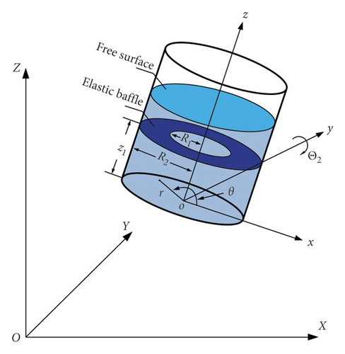
As plotted in Figure 1, the rigid cylindrical tank equipped with the single flexible baffle is partially filled with ideal liquid. O-XYZ denotes the inertial coordinate, while o-xyz and o-rθz are, respectively, the Cartesian and cylindrical coordinates which are fixed to the moving tank. The outer boundary of the annular baffle is clamped to the container, and the inner boundary of the baffle is free. The surface wave height relative to the static liquid level can be expressed as z = f(r, θ, z). The tank is undergoing the pitching excitation denoted as Θ2(t). The rotation axis of the pitching tank is y-axis. The linearized boundary-value problem for the velocity potential Φ is
1 r r r Φ r + 1 r 2 2 Φ θ 2 + 2 Φ z 2 = 0 in Ω , (1)
Φ r = z Θ ˙ 2 cos θ on the wall of the tank , (2)
Φ z = r Θ ˙ 2 cos θ on the bottom of the tank , (3)
in which Ω denotes the liquid domain. The velocity of the liquid particle on the free surface should be equal to the velocity of the liquid-free surface. One can obtain the kinematic boundary condition on the free surface [27]:
Φ z = r Θ ˙ 2 cos θ + f t on the free surface . (4)
Details are in the caption following the image
Cylindrical container with single elastic baffle under pitching excitations.
The liquid pressure is equal to the gas pressure above the liquid-free surface. This gives the dynamic boundary condition on the free surface [27]:
Φ t = g r Θ 2 cos θ f g on the free surface , (5)
where g is the gravitational acceleration. There is no liquid outflow or inflow in this problem. Thus, the volume of the liquid remains constant, namely,
Σ 0 f r d r d θ = 0. (6)
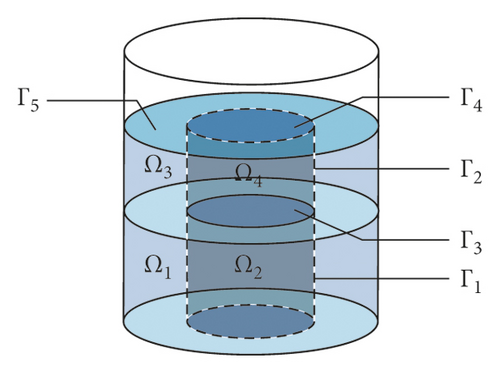
As plotted in Figure 2, the single flexible baffle is positioned at z1 and the liquid domain Ω can be divided into 4 subdomains by 3 artificial interfaces. The notation Φi (i = 1, 2, 3, and 4) represents the velocity potential within the subdomain Ωi. The compatibility condition requires the liquid velocity in contact with the flexible baffle to be the same as the velocity of the baffle, that is,
Φ z z = z 1 = r Θ ˙ 2 cos θ + w t , (7)
where w is the dynamic deflection of the baffle. The baffle is modeled by a thin elastic plate and is assumed to be made of linearly elastic, homogeneous, and isotropic material. Moreover, the effect of shear deformation and rotary inertia is neglected. According to [28, 29], the dynamic deflection satisfies the coupled dynamic equation:
D 4 w + ρ τ 2 w t 2 = ρ l Φ 3 t z = z 1 ρ l Φ 1 t z = z 1 , D = E τ 3 12 1 ν 2 , (8)
where τ, ρ, ν, and E denote the thickness, density, Poisson’s ratio, and Young’s modulus for the single flexible baffle, respectively; ρl denotes the density of the liquid; R2 is the baffle’s outer radius which is equal to the inner radius of the tank; h denotes the static liquid level; and R1 represents the baffle’s inner radius. Five dimensionless coordinates, i.e., ξ = r/R2, ξ1 = R1/R2, ς = z/R2, ς1 = z1/R2, and ς0 = h/R2, are introduced. For purpose of solving the boundary-value problem (Equations (1)–(8)), the velocity potential can be decomposed into two parts: the potential ΦR representing the rigid body motion of the liquid which is concerned with the container motion and the potential ΦS representing the liquid motion relative to the container which is concerned with the liquid sloshing. In order to describe the pitching motion of the container, the Stokes–Joukowski potential is introduced. According to [27], the potential ΦR can be expressed as follows:
Φ R = Θ ˙ 2 Ψ 2 ξ , θ , ς , (9)
where Ψ2 denotes the component of the Stokes–Joukowski potential along y-axis, which is associated with the pitching motion about y-axis. The potential ΦS, the surface wave height f, and the dynamic deflection w can be expressed as a summation of the coupled modes. Introducing the time-dependent generalized coordinates qmn(t), q m n t , and Rmn(t), one can obtain the following function series:
f = q m n t f m n ξ cos m θ , (10)
w = q m n t W m n ξ cos m θ , (11)
Φ = Φ R + Φ S = Θ ˙ 2 Ψ 2 ξ , θ , ς + R m n t φ m n ξ , ς cos m θ , (12)
in which φmn is the coupled mode of the liquid, fmn(ξ) satisfies fmn(ξ) = φmn(ξ, ς0), and Wmn is the coupled mode of the flexible baffle. The detailed definitions of coupled modes Wmn and φmn are referred to the coupled eigenvalue problem [30]. In the literature, the liquid in the baffled tank was partitioned into several subdomains. By the method of separation of variables, the trial solution for the velocity potential corresponding to each subdomain was solved. The eigenfrequency equation can be established by expanding the free surface condition, the artificial interface conditions and coupled vibration equations into the Fourier series in the liquid height direction, and the Bessel series in the radial direction. The natural modes and frequencies ωmn can be obtained by solving the eigenfrequency equation. According to the literature, the coupled modes satisfy the following equations:
φ m n 1 ς ς = ς 1 = φ m n 3 ς ς = ς 1 = R 2 W m n , D 4 W m n cos m θ = g Λ m n 2 R 2 ρ τ W m n + ρ l φ m n 1 φ m n 3 ς = ς 1 cos m θ , (13)
where φ m n i (i = 1, 2, 3, and 4) denotes the coupled mode corresponding to the subdomain Ωi and the dimensionless frequency Λmn satisfies Λ m n 2 = ω m n 2 R 2 / g . Substituting Equations (10)–(12) into the kinematic conditions, Equations (4) and (7) on the free surface and the flexible baffle, respectively, gives
R m n t Λ m n 2 φ m n = q ˙ m n t φ m n on the free surface , R m n t g Λ m n 2 R 2 ρ τ W m n + ρ l φ m n 1 φ m n 3 ς = ς 1 = q ˙ m n t g Λ m n 2 R 2 ρ τ W m n + ρ l φ m n 1 φ m n 3 ς = ς 1 on the baffle . (14)
Details are in the caption following the image
Subdomains and interfaces.
The orthogonality condition of the coupled modes [30] leads to the following relations among the generalized coordinates:
R m n t = R 2 q ˙ m n t Λ m n 2 , q m n t = R 2 q m n t Λ m n 2 . (15)

3. Stokes–Joukowski Potential

The notation Ψ is introduced as the Stokes–Joukowski potential. According to Wang et al. [26], Ψ satisfies the following equations:
Δ Ψ = 0 in Ω , (16)
Ψ n = r × n on S 0 Σ 0 , (17)
where Σ0 represents the mean liquid-free surface, S0 denotes the wetted surface of the tank and the baffle, r denotes the radius vector with respect to the origin of o-xyz, and n is the outer normal vector of Σ0 and S0. According to Equation (12), only the component Ψ2 along y-axis needs to be considered. According to Equations (16) and (17), Ψ2 satisfy
Δ Ψ 2 = 0 in Ω , (18)
Ψ 2 ς = R 2 2 ξ cos θ on the bottom of the tank ,  the free surface ,  and the baffle , (19)
Ψ 2 ξ = R 2 2 ς cos θ on the wall of the tank . (20)
Obviously, the dimensionless component ψ 2 = Ψ 2 / R 2 2 can be introduced. According to Equations (19) and (20), we have
ψ 2 = ς ξ ψ cos θ , (21)
where ψ satisfies the following equations:
2 ψ ξ 2 + 1 ξ ψ ξ ψ ξ 2 + 2 ψ ς 2 = 0 in Ω , ψ ξ = 0 on the wall of the tank , ψ ς = 2 ξ on the bottom of the tank ,  the free surface, and the baffle . (22)
The liquid domain in the baffled tank is divided into 4 subdomains, and the function ψ within the subdomains can be expressed as
ψ ξ , ς = ψ i ξ , ς in Ω i i = 1234 , , ,  and  , (23)
where ψi satisfies the Laplace equation Δψi = 0 and Γk denotes the interface between two neighboring subdomains (Ωi and Ω i ). Apparently, the neighboring subdomains satisfy the following continuity conditions:
ψ i = ψ i , ψ i n k = ψ i n k on Γ k , (24)
where n k denotes the vector normal to the interface and ψi (i = 1, 2, 3, and 4) can be solved using the analytical method, which was proposed by Wang et al. [26].

4. Coupled Response Equations

Substituting Equations (11) and (12) into the dynamics conditions on the flexible baffle, Equation (8) yields
q m n t Λ m n 2 g R 2 ρ τ W m n + ρ l φ m n 1 φ m n 3 ς = ς j cos m θ + q ¨ m n t ρ τ W m n cos m θ = R 2 2 ρ l Θ ¨ 2 ψ 1 ψ 3 ς = ς 1 cos θ + R ˙ m n t ρ l φ m n 3 φ m n 1 ς = ς 1 cos m θ . (25)
According to Equation (15), Equation (25) can be rewritten as
q m n t g ρ τ W m n + ρ l φ m n 1 φ m n 3 ς = ς 1 cos m θ + R 2 q ¨ m n t Λ m n 2 ρ τ W m n cos m θ = R 2 2 ρ l Θ ¨ 2 ψ 1 ψ 3 ς = ς 1 cos θ + R 2 q ¨ m n t Λ m n 2 ρ l φ m n 3 φ m n 1 ς = ς 1 cos m θ . (26)
Substituting Equations (10) and (12) into the dynamics condition on the free surface, Equation (5) gives
R 2 q ¨ m n t Λ m n 2 f m n ξ cos m θ + g q m n t f m n ξ cos m θ g Θ 2 ξ + Θ ¨ 2 ψ Σ 0 ς 0 ξ R 2 R 2 cos θ = 0. (27)
According to the orthogonality of the cosine functions, Equations (26) and (27) can be rewritten as
q ¨ 1 n t Λ 1 n 2 τ W 1 n ρ ρ l + φ 1 n 1 φ 1 n 3 ς = ς 1 + g R 2 q 1 n t τ W 1 n ρ ρ l + φ 1 n 1 φ 1 n 3 ς = ς 1 + R 2 Θ ¨ 2 ψ 3 ψ 1 ς = ς 1 = 0. q ¨ 1 n t Λ 1 n 2 f 1 n ξ + g R 2 q 1 n t f 1 n ξ g Θ 2 ξ + Θ ¨ 2 ψ Σ 0 ς 0 ξ R 2 = 0 , (28)
According to the orthogonality condition of the coupled modes [30], the dynamics equation corresponding to the generalized coordinate qn(t) can be obtained:
M 1 n q ¨ 1 n t + q 1 n t K 1 n = F t , (29)
in which M1n, K1n, and F(t) can be written as
M 1 n = 0 1 f 1 n f 1 n ξ d ξ + ξ 1 1 τ W 1 n ρ / ρ l + φ 1 n 1 φ 1 n 3 ς = ς 1 W 1 n ξ d ξ Λ 1 n 2 , (30)
K 1 n = Λ 1 n 2 g R 2 M 1 n , (31)
F t = g Θ 2 0 1 f 1 n ξ 2 d ξ + Θ ¨ 2 0 1 f 1 n ψ Σ 0 ξ d ξ ς 0 0 1 f 1 n ξ 2 d ξ R 2 + R 2 Θ ¨ 2 ξ 1 1 ψ 1 ψ 3 ς = ς j W 1 n ξ d ξ . (32)
The liquid sloshing in the baffled container will be damped. The convenient way to account for the sloshing damping phenomenon generally happening in the real world is to introduce additional damping terms. So, Equation (33) takes the form:
M 1 n q ¨ 1 n t + 2 ζ q ˙ 1 n M 1 n K 1 n + q 1 n t K 1 n = F t , (33)
in which ζ denotes the damping ratio. According to the Bernoulli principle, the hydrodynamic pressure is solved using the following formula:
P ξ , θ , ς , t = ρ Φ t = ρ R 2 cos θ Θ ¨ 2 ς ξ ψ R 2 + q ¨ 1 n t φ 1 n Λ 1 n 2 . (34)
Integrating the pressure function P(ξ, θ, ς, t) on the tank wall, the resultant force for the hydrodynamic pressure which acts on the tank wall can be calculated. The component of the resultant force along the θ = 0 direction can be written as follows:
F x = ρ R 2 3 π q ¨ 1 n t Λ 1 n 2 0 ς 0 φ 1 n ξ = 1 d ς + ρ R 2 4 π Θ ¨ 2 0 ς 0 ψ ξ = 1 d ς ς 0 2 2 . (35)
The moment caused by liquid pressure which acts on the tank wall about the θ = π/2 axis can be written as follows:
M wall y = ρ R 2 4 π q ¨ 1 n t Λ 1 n 2 0 ς 0 φ 1 n ξ = 1 ς d ς ρ R 2 5 π Θ ¨ 2 0 ς 0 ψ ξ = 1 ς d ς ς 0 3 3 . (36)
The moment caused by liquid pressure which acts on the bottom of the tank about the θ = π/2 axis can be written as follows:
M bottom y = ρ R 2 4 π q ¨ 1 n t Λ 1 n 2 0 1 φ 1 n ς = 0 ξ 2 d ξ ρ R 2 5 π Θ ¨ 2 0 1 ψ ς = 0 ξ 2 d ξ . (37)
The moment caused by liquid pressure which acts on the flexible baffle about the θ = π/2 axis can be written as follows:
M baffle y = ρ R 2 4 π q ¨ 1 n t Λ 1 n 2 ξ 1 1 φ 1 n 3 φ 1 n 1 ς = ς 1 ξ 2 d ξ R 2 Θ ¨ 2 ξ 1 1 ψ 3 ψ 1 ς = ς 1 ξ 2 d ξ . (38)
According to Equations (36)–(38), the resultant moment can be written as
M y = M wall y + M bottom y + M baffle y . (39)

5. Method Validation

The analytical model was validated by comparing with the numerical results, which were simulated using the finite element software ADINA (version 9.3.4). The potential-based fluid elements of ADINA are the efficient way to model the fluid. The elements have only one degree of freedom per node and can be coupled to ADINA structural elements and the pressure boundary condition by the interface elements. In many cases, ADINA can automatically generate the interface elements along the boundary of the liquid. The fluid-structure interface element connects the potential-based fluid element with an adjacent structural element. The free surface interface element is placed onto the boundary of a potential-based fluid element where the pressure has to be prescribed and the displacements of the fluid are required.

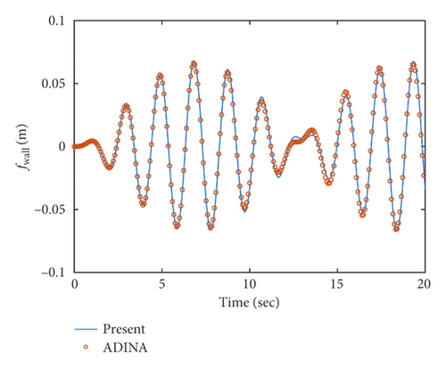
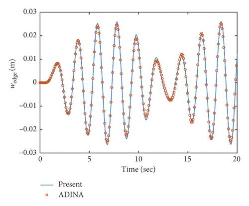
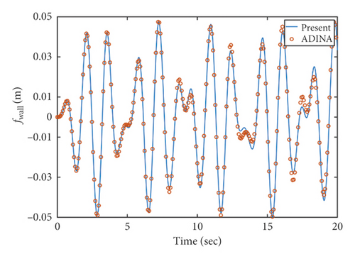
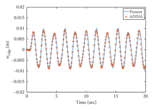
The angular displacement of the pitching excitation follows a sinusoidal function Θ2 = Θ0sin ω0t, where ω0 and Θ0 denote the frequency and amplitude of the excitation, respectively. The parameters for the liquid, the flexible baffle, and the tank in the comparison study have been listed in Table 1. The inner radius of the baffle was set as R1 = 0.5 m, and the baffle was installed at z1 = 0.6 m. The excitation frequencies were taken as ω0 = 3 rad/s, 4 rad/s, and 5 rad/s. As depicted in Figures 35, the deflection of the flexible baffle at the inner edge for θ = 0 and the surface wave heights on the wall fwall at θ = 0 obtained from the present analytical method were compared with those which were obtained from the ADINA model. Figures 35 show that the analytical solutions are in good agreement with the numerical results simulated by the ADINA.

Table 1. Parameters for the liquid and the baffled container in the comparison analysis.
Description Parameter Value
Inner radius of the container (m) R2 1
Height of the liquid (m) h 1
Density of the liquid (kg/m3) ρl 1000
Thickness of the baffle (mm) τ 2
Density of the baffle (kg/m3) ρ 2870
Poisson ratio of the baffle ν 0.3
Elastic modulus of the baffle (Pa) E 7.2e10
Amplitude of the excitation (rad) Θ0 0.01
Details are in the caption following the image
The time histories of the surface wave height on the wall (θ = 0) and the dynamic deflection of the baffle at the inner edge (θ = 0) for ω0 = 3 rad/s. (a) surface wave height on the wall, (b) dynamic deflection of the baffle at the inner edge.
Details are in the caption following the image
The time histories of the surface wave height on the wall (θ = 0) and the dynamic deflection of the baffle at the inner edge (θ = 0) for ω0 = 3 rad/s. (a) surface wave height on the wall, (b) dynamic deflection of the baffle at the inner edge.
Details are in the caption following the image
The time histories of the surface wave height on the wall (θ = 0) and the dynamic deflection of the baffle at the inner edge (θ = 0) for ω0 = 4 rad/s. (a) surface wave height on the wall, (b) dynamic deflection of the baffle at the inner edge.
Details are in the caption following the image
The time histories of the surface wave height on the wall (θ = 0) and the dynamic deflection of the baffle at the inner edge (θ = 0) for ω0 = 4 rad/s. (a) surface wave height on the wall, (b) dynamic deflection of the baffle at the inner edge.
Details are in the caption following the image
The time histories of the surface wave height on the wall (θ = 0) and the dynamic deflection of the baffle at the inner edge (θ = 0) for ω0 = 5 rad/s. (a) surface wave height on the wall, (b) dynamic deflection of the baffle at the inner edge.
Details are in the caption following the image
The time histories of the surface wave height on the wall (θ = 0) and the dynamic deflection of the baffle at the inner edge (θ = 0) for ω0 = 5 rad/s. (a) surface wave height on the wall, (b) dynamic deflection of the baffle at the inner edge.

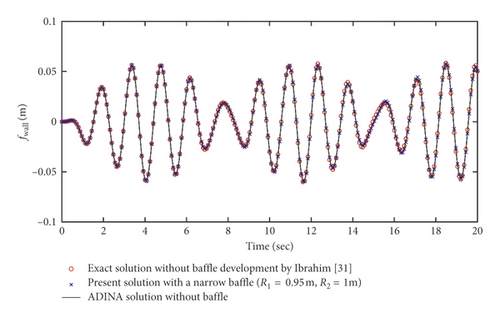
When the inner radius of the baffle approaches that of the tank, the radial width of the annular baffle is very small. Currently, the baffle has very small effects on the liquid sloshing. To further verify the correctness of this method, the solution from the present analytical method was compared with the exact solution without the baffle developed by Ibrahim [31]. In this case, the inner radius of the baffle was set as R1 = 0.95 m and the baffle was installed at z1 = 0.5 m. The excitation frequency was taken as ω0 = 5 rad/s. It can be observed from Figure 6 that the difference between the solution obtained by the present analytical and the exact solution is very small. To verify the correctness of the ADINA model, a liquid storage model without the baffle was established to compare the numerical solution with the exact solution. From Figure 6, the numerical solution is in good agreement with the exact solution.
Details are in the caption following the image
Comparisons of the time histories of the surface wave height on the wall (θ = 0) among the exact solution, ADINA solution and present analytical result for ω0 = 5 rad/s.

6. Steady-State Response

The steady-state solution of the coupled response undergoing the pitching sinusoidal excitations is conducted to explore the effectiveness of the flexible baffle in reducing the liquid sloshing. Substituting the pitching sinusoidal excitations into Equation (32), one can obtain the following formula:
F t = F 1 n sin ω 0 t , (40)
in which F1n satisfies the following equation:
F 1 n = Θ 0 g 0 1 f 1 n ξ 2 d ξ ω 0 2 R 2 0 1 ψ ς ξ Σ 0 f 1 n ξ d ξ + ξ 1 1 ψ 1 ψ 3 ς = ς 1 W 1 n ξ d ξ . (41)
According to Equation (33), the steady-state response can be obtained in the following form:
q 1 n t = A 1 n sin ω 0 t B 1 n cos ω 0 t , (42)
in which A1n and B1n satisfy
A 1 n = F 1 n K 1 n 1 β 1 n 2 1 β 1 n 2 2 + 2 ζ β 1 n 2 , B 1 n = F 1 n K 1 n 2 ζ β 1 n 1 β 1 n 2 2 + 2 ζ β 1 n 2 , β 1 n = ω 0 / ω 1 n . (43)
Substituting Equation (42) into Equation (10) gives the steady-state response for the surface wave height on the wall of the tank at θ = 0:
f wall = sin ω 0 t A 1 n f 1 n ξ = 1 cos ω 0 t B 1 n f 1 n ξ = 1 . (44)
Substituting Equation (42) into Equation (35) gives the steady-state response for the resultant force along the x-axis:
F x = F x 1 sin ω 0 t + F x 2 cos ω 0 t , (45)
in which Fx1 and Fx2 satisfy the following equation:
F x 1 = ρ R 2 3 π ω 0 2 A 1 n Λ 1 n 2 0 ς 0 φ 1 n ξ = 1 d ς R 2 Θ 0 0 ς 0 ψ ξ = 1 d ς ς 0 2 2 , F x 2 = ρ R 2 3 π ω 0 2 B 1 n Λ 1 n 2 0 ς 0 φ 1 n ξ = 1 d ς . (46)
Substituting Equation (42) into Equation (39) gives the steady-state response for the resultant moment about the y-axis:
M y = M y 1 sin ω 0 t + M y 2 cos ω 0 t , (47)
in which My1 and My2 satisfy the following equation:
M y 1 = ρ R 2 4 π ω 0 2 R 2 Θ 0 0 ς 0 ψ ξ = 1 ς d ς + 0 1 ψ ς = 0 ξ 2 d ξ + ξ 1 1 ψ 3 ψ 1 ς = ς 1 ξ 2 d ξ ς 0 3 3 A 1 n Λ 1 n 2 0 1 φ 1 n ς = 0 ξ 2 d ξ + 0 ς 0 φ 1 n ξ = 1 ς d ς + ξ 1 1 φ 1 n 3 φ 1 n 1 ς = ς 1 ξ 2 d ξ , M y 2 = ρ R 2 4 π ω 0 2 B 1 n Λ 1 n 2 0 1 φ 1 n ς = 0 ξ 2 d ξ + 0 ς 0 φ 1 n ξ = 1 ς d ς + ξ 1 1 φ 1 n 3 φ 1 n 1 ς = ς 1 ξ 2 d ξ . (48)
According to Equations (44), (45), and (47), fwall, Fx, and My can be written as
f wall = f max sin ω 0 t ϕ 1 , F x = F max sin ω 0 t ϕ 2 , M y = M max sin ω 0 t ϕ 3 , (49)
in which fmax, Fmax, and Mmax are the maximum amplitudes of the steady-state responses. ϕ1, ϕ2, and ϕ3 are the phases of fwall, Fx, and My. The maximum amplitudes of the steady-state responses satisfy the following equations:
f max = A 1 n f 1 n ξ = 1 2 + B 1 n f 1 n ξ = 1 2 , F max = F x 1 2 + F x 2 2 , M max = M y 1 2 + M y 2 2 . (50)

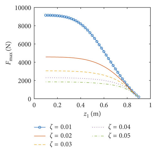
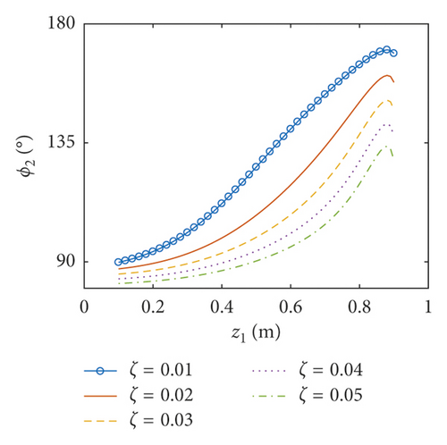
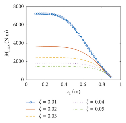
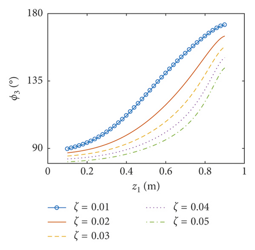
The coupled steady-state responses versus the parameters of the elastic baffle (the inner radius R1, the position z1, and the thickness τ) are systematically investigated. Five different artificial damping ratios are considered: ζ = 0.01, 0.02, 0.03, 0.04, and 0.05. The excitation frequency is taken as ω0 = 4.14 rad/s, which is close to the first natural frequency of the liquid sloshing in the container with no baffle. To study the influence of the baffle’s inner radius R1, the baffle is installed at z1 = 0.7 m and the thickness of the baffle is fixed at τ = 2 mm. To study the effect of the baffle’s position z1, the inner radius of the baffle is taken as R1 = 0.4 m and the thickness of the baffle is fixed at τ = 2 mm. The effect of the thickness of the baffle is discussed when the baffle is located at z1 = 0.7 m, and the baffle’s inner radius is fixed at R1 = 0.5 m. Other parameters for the steady-state analysis have been listed in Table 2.

Table 2. The parameters for the baffled container in the steady-state analysis.
Description Parameter Value
Inner radius of the container (m) R2 1
Height of the liquid (m) h 1
Density of the liquid (kg/m3) ρl 1000
Density of the baffle (kg/m3) ρ 2870
Poisson ratio of the baffle ν 0.3
Elastic modulus of the baffle (Pa) E 7.2e9
Amplitude of the excitation (rad) Θ0 0.01

6.1. Coupled Responses versus the Inner Radius of the Baffle

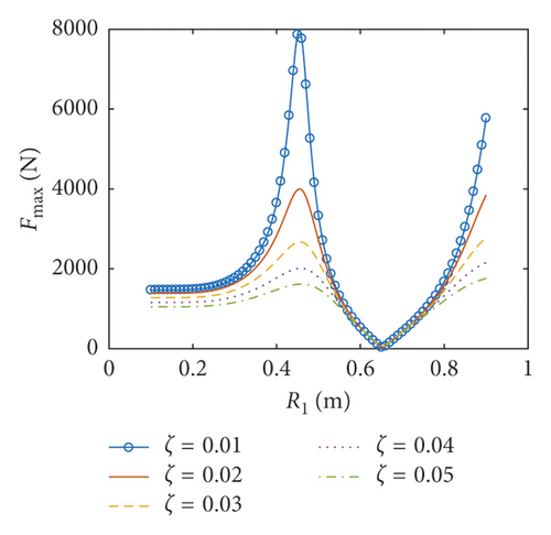
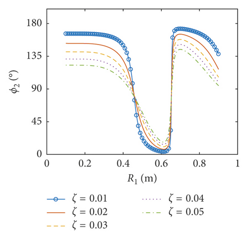
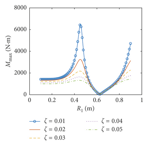
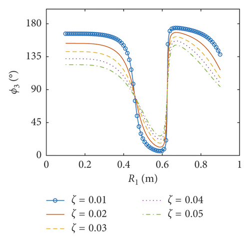
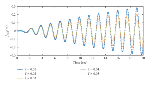
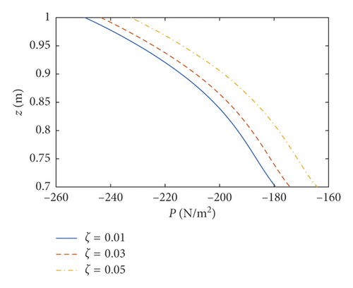
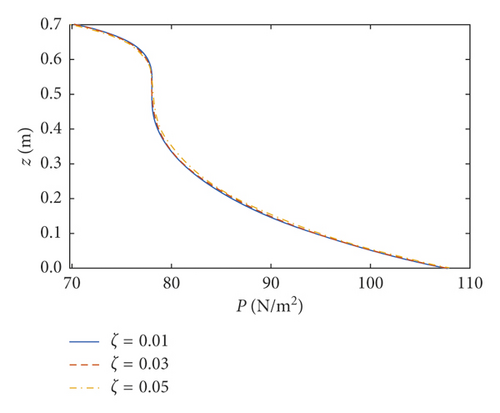
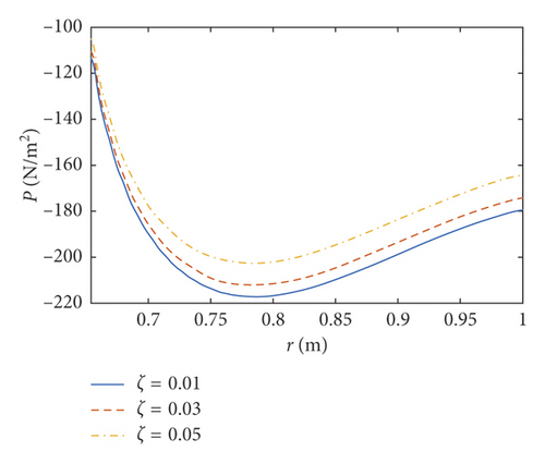
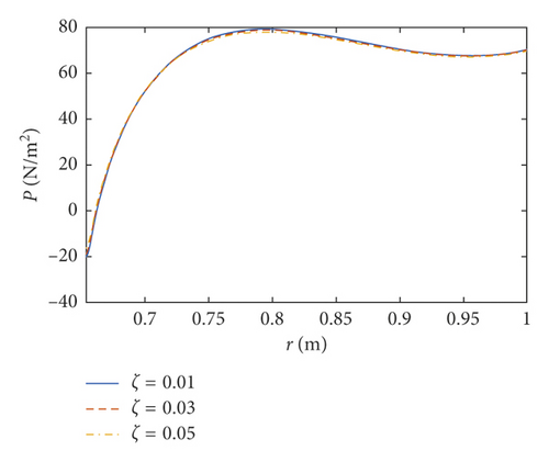
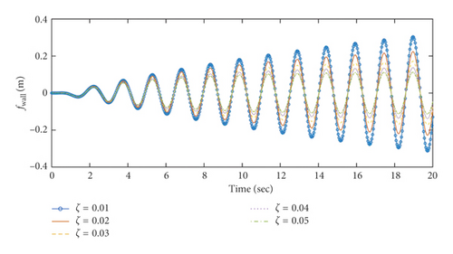
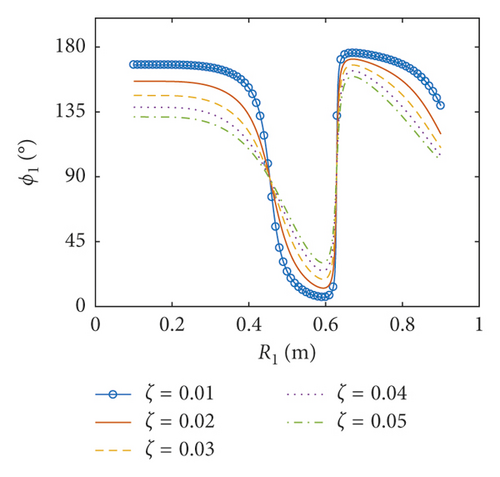
The amplitudes of the surface wave height, the resultant force, and the moment versus the inner radius of the baffle are plotted in Figures 79, respectively. The corresponding phases are also illustrated. According to Figures 79, when the inner radius of the flexible baffle is smaller than 0.3 m, the coupled dynamic responses do not change significantly as the inner radius increases. In fact, the change in the area of the baffle is the main factor leading to the variation of the coupled response. When the inner radius of the baffle is small, the rate of change of its area is small. Therefore, the variation of the coupled response is negligible. When the inner radius is bigger than 0.3 m, the coupled dynamic responses increase rapidly with the increase of the inner radius. When the inner radius is 0.45 m, there are peaks in the curves. The excitation frequency is close to the natural frequency of the coupled system, and the corresponding phases are 90°. Therefore, the resonance will occur, which increases the amplitude of the coupled response rapidly. However, such an increase can be effectively reduced by the damping ratio. Figure 10 gives the resonant time histories of the surface wave height for different damping ratios. As the inner radius increases continuously, fmax, Fmax, and Mmax decrease rapidly, reaching the minimum values when the inner radius is 0.628 m, 0.652 m, and 0.626 m, respectively. At the minimum of the coupled response, the corresponding phase will undergo the abrupt change from close to 0° to almost 180°. When Fmax reaches the lowest point (R1 = 0.652 m and z1 = 0.7 m), the pressure distributions on the tank wall and baffle are plotted in Figure 11. The effect of sloshing is more profound in the liquid above the baffle, and the pressure due to the sloshing portion at θ = 0 is out of phase with the excitation. The pressure due to the liquid below the baffle at θ = 0 is in phase with the excitation. The effect of the damping ratio on the pressure due to the sloshing portion is more significant than on the pressure due to the liquid below the baffle. The coupled dynamic responses increase rapidly with the continuously increasing inner radius. When the baffle is narrow, the effects of the baffle on liquid sloshing are sharply reduced with the increase of the inner radius of the baffle, and the natural frequency is close to the case without the baffle, which causes the resonance.

Details are in the caption following the image
The amplitudes and the phases of the surface wave height versus the inner radius of the flexible baffle for z1 = 0.7 m and τ = 2 mm. (a) the amplitude of the surface wave height, (b) the phase of the surface wave height.
Details are in the caption following the image
The amplitudes and the phases of the surface wave height versus the inner radius of the flexible baffle for z1 = 0.7 m and τ = 2 mm. (a) the amplitude of the surface wave height, (b) the phase of the surface wave height.
Details are in the caption following the image
The amplitudes and the phases of the resultant force versus the inner radius of the flexible baffle for z1 = 0.7 m and τ = 2 mm. (a) the amplitude of the resultant force, (b) the phase of the resultant force.
Details are in the caption following the image
The amplitudes and the phases of the resultant force versus the inner radius of the flexible baffle for z1 = 0.7 m and τ = 2 mm. (a) the amplitude of the resultant force, (b) the phase of the resultant force.
Details are in the caption following the image
The amplitudes and the phases of resultant moment versus the inner radius of the flexible baffle for z1 = 0.7 m and τ = 2 mm. (a) the amplitude of the resultant moment, (b) the phase of the resultant moment.
Details are in the caption following the image
The amplitudes and the phases of resultant moment versus the inner radius of the flexible baffle for z1 = 0.7 m and τ = 2 mm. (a) the amplitude of the resultant moment, (b) the phase of the resultant moment.
Details are in the caption following the image
The resonant time histories of the surface wave height on the wall (θ = 0) for z1 = 0.7 m, R1 = 0.45 m and τ = 2 mm.
Details are in the caption following the image
The pressure distributions on the tank wall and baffle at θ = 0 when ω0t = π/2 for z1 = 0.7 m, R1 = 0.652 m and τ = 2 mm. (a) The pressure distribution of the tank wall above the baffle, (b) The pressure distribution of the tank wall below the baffle, (c) The pressure distribution acting on the upper surface of the baffle, (d) The pressure distribution acting on the lower surface of the baffle.

6.2. Coupled Responses versus the Position of the Baffle

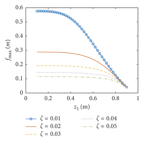
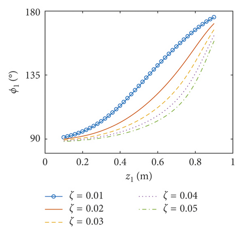
The amplitudes of the surface wave height, the resultant force, and the moment versus the position of the baffle are plotted in Figures 1214, respectively. The corresponding phases are also illustrated. According to Figures 1214, the coupled dynamic responses become stronger when the baffle approaches the bottom of the container. When the flexible baffle is far from the free surface of the liquid, the baffle has relatively little influence on the liquid sloshing, and the excitation frequency is close to the first natural frequency of the coupled system. Therefore, the system generates resonance under the external excitation, leading to large amplitude of the coupled response. Currently, the amplitude of the coupled response decreases with the increase of the damping ratio. In addition, the phases for ζ = 0.01 approximate 90°. When the baffle is located at z1 = 0.1 m, the resonant time histories of the surface wave height for different damping ratios are plotted in Figure 15. As the flexible baffle ascends, the coupled dynamic responses corresponding to different damping ratios gradually reduce to the same minimum value. Meanwhile, the natural frequency of the system is less than the excitation frequency, and the amplitude of the coupled response is very small. This is mainly because the direction of external excitation changes so fast that the liquid sloshing cannot change accordingly as a result of the inertial effects. At this moment, the phases for ζ = 0.01 approximate 180°. Thus, the effectiveness of the sloshing reduction can be improved when the flexible baffle is installed near the free surface (Figures 1618).

Details are in the caption following the image
The amplitudes and the phases of the surface wave height versus the position of the flexible baffle for R1 = 0.4 m and τ = 2 mm. (a) the amplitude of the surface wave height, (b) the phase of the surface wave height.
Details are in the caption following the image
The amplitudes and the phases of the surface wave height versus the position of the flexible baffle for R1 = 0.4 m and τ = 2 mm. (a) the amplitude of the surface wave height, (b) the phase of the surface wave height.
Details are in the caption following the image
The amplitudes and the phases of the resultant force versus the position of the flexible baffle for R1 = 0.4 m and τ = 2 mm. (a) the amplitude of the resultant force, (b) the phase of the resultant force.
Details are in the caption following the image
The amplitudes and the phases of the resultant force versus the position of the flexible baffle for R1 = 0.4 m and τ = 2 mm. (a) the amplitude of the resultant force, (b) the phase of the resultant force.
Details are in the caption following the image
The amplitudes and the phases of resultant moment versus the position of the flexible baffle for R1 = 0.4 m and τ = 2 mm. (a) the amplitude of the resultant moment, (b) the phase of the resultant moment.
Details are in the caption following the image
The amplitudes and the phases of resultant moment versus the position of the flexible baffle for R1 = 0.4 m and τ = 2 mm. (a) the amplitude of the resultant moment, (b) the phase of the resultant moment.
Details are in the caption following the image
The resonant time histories of the surface wave height on the wall (θ = 0) for z1 = 0.1 m, R1 = 0.4 m and τ = 2 mm.
Details are in the caption following the image
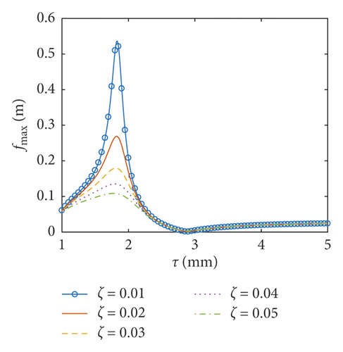
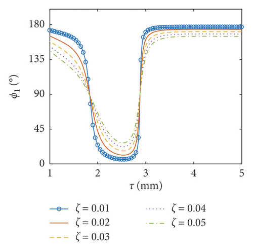
The amplitudes and the phases of the surface wave height versus the thickness of the flexible baffle for R1 = 0.5 m and z1 = 0.7 m. (a) the amplitude of the surface wave height, (b) the phase of the surface wave height.
Details are in the caption following the image
The amplitudes and the phases of the surface wave height versus the thickness of the flexible baffle for R1 = 0.5 m and z1 = 0.7 m. (a) the amplitude of the surface wave height, (b) the phase of the surface wave height.
Details are in the caption following the image
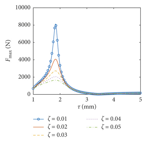
The amplitudes and the phases of the resultant force versus the thickness of the flexible baffle for R1 = 0.5 m and z1 = 0.7 m. (a) the amplitude of the resultant force, (b) the phase of the resultant force.
Details are in the caption following the image
The amplitudes and the phases of the resultant force versus the thickness of the flexible baffle for R1 = 0.5 m and z1 = 0.7 m. (a) the amplitude of the resultant force, (b) the phase of the resultant force.
Details are in the caption following the image
The amplitudes and the phases of resultant moment versus the thickness of the flexible baffle for R1 = 0.5 m and z1 = 0.7 m. (a) the amplitude of the resultant moment, (b) the phase of the resultant moment.
Details are in the caption following the image
The amplitudes and the phases of resultant moment versus the thickness of the flexible baffle for R1 = 0.5 m and z1 = 0.7 m. (a) the amplitude of the resultant moment, (b) the phase of the resultant moment.

6.3. Coupled Responses versus the Thickness of the Baffle

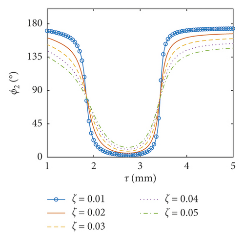
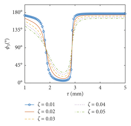
In this part, the thickness of the baffle ranges between 0.001 m and 0.005 m and the inner radius of the baffle is taken as 0.5 m. Obviously, the thickness of the baffle is much less than the dimensions of the baffle. As a result, the assumption of the thin plate can be applied here. The amplitudes of the surface wave height, the resultant force, and the moment versus the thickness of the flexible baffle are plotted in Figures 1214, respectively. The corresponding phases are also illustrated. The coupled responses increase rapidly the increase of the thickness of the baffle. When the thickness of the baffle increases to 1.83 mm, there are peaks in the curves. This is because the excitation frequency is close to the third natural frequency of the coupled system, and the peak decreases with the increasing damping ratio. At this point, the phases are 90°. As the thickness increases continuously, fmax, Fmax, and Mmax decrease rapidly, reaching the minimum values when the thickness of the baffle is 2.88 mm, 3.43 mm, and 2.82 mm, respectively, and the phases approximate 90°. The influence of the damping ratio on the amplitudes of the coupled dynamic response can be ignored when the thickness of the baffle is bigger than 2.55 mm. This is mainly because the baffle has a greater influence on the natural frequency of the liquid sloshing as the stiffness increases, making the natural frequency of the liquid sloshing far away from the excitation frequency.

7. Conclusion

The coupled dynamic response of partially liquid-filled cylindrical tank equipped with single flexible baffle subjected to the pitching excitation has been analytically investigated. Introducing the generalized coordinates, the velocity potential containing the Stokes–Joukowski potential is formulated. The Stokes–Joukowski potential can be calculated using the analytical method [26]. According to coupled conditions on the flexible baffle and the boundary conditions on the free surface, the coupled dynamic response equation can be obtained. Compared with the numerical results which were simulated by ADINA, the analytical method is verified. The following observations are drawn:
  • (1)

    The introduction of the damping term can reflect the dissipation effect when the excitation frequency is close to the natural frequency of the coupled system.

  • (2)

    The effectiveness of the sloshing reduction can be improved when the flexible baffle is installed near the free surface.

  • (3)

    The baffle has a greater influence on the natural frequency of the liquid sloshing as the stiffness increases, making the natural frequency of the liquid sloshing far away from the excitation frequency.

Conflicts of Interest

The authors declare that they have no conflicts of interest.

Acknowledgments

This work was supported by the grants from the Jiangsu Natural Science Fund Project (BK20160482), the Natural Science Fund for Colleges and Universities in Jiangsu Province (16KJB130001), and the National Natural Science Foundation of China (Grant no. 11702117).

    Data Availability

    The data used to support the findings of this study are available from the corresponding author upon request.

      The full text of this article hosted at iucr.org is unavailable due to technical difficulties.