Profile-Tracking-Based Adaptive Guidance Law against Maneuvering Targets
Abstract
For the terminal guidance problem of a missile intercepting a maneuvering target, a profile-tracking-based adaptive guidance law is proposed with inherent continuity in this paper. To flexibly and quantitatively control the convergence rate of the line-of-sight rate, a standard tracking profile is designed where the convergence rate is analytically given. Then, a nonsingular fast terminal sliding-mode control approach is used to track the profile. By estimating the square of the upper bound of target maneuver, an adaptive term is constructed to compensate the maneuver. Therefore, no information of target acceleration is required in the derived law. Stability analysis shows that the tracking error can converge to a small neighborhood of zero in finite time. Furthermore, a guidance-command-conversion scheme is presented to convert the law into the one appropriate for endoatmospheric interceptions. Simulation results indicate that the proposed law is effective and outperforms existing guidance laws.
1. Introduction
The terminal guidance law of a missile plays a crucial role in making a successful intercept, and the guidance performance of the law exerts a direct influence on miss distance, control efforts, etc. Proportional navigation (PN) and its variants are widely applied in a considerable variety of intercept engagements due to inherent simplicity and high effectiveness [1–3]. However, with enhancement of target maneuverability, PN suffers from a significant degradation of intercept performance because of limited capability to suppress rotation of the line of sight (LOS) between a missile and a target induced by target maneuver. Then, the augmented PN was proposed to compensate target maneuver, but the price paid is the information of target acceleration which cannot be measured directly and is difficult to be accurately estimated [4, 5]. To meet the challenge of precisely intercepting agile targets, some advanced control algorithms have been used to develop robust guidance laws, such as sliding mode control [6–11], nonlinear H∞ control [12], dynamic surface control [13], and finite time control [14–18].
Sliding mode control (SMC) is a simple and effective approach to handling external disturbances and system uncertainties, which attracts considerable attention paid to applying SMC to intercept guidance. The SMC-based guidance law can achieve the robustness to target maneuver and consequently outperforms the PN law [6–11]. However, most of the SMC-based guidance laws provide only the asymptotic or exponential stability of a guidance system, which indicates that the LOS rate (LOSR) is driven to zero or its small neighborhood only as time approaches infinity. Since the terminal phase of interception is of short duration, it is the convergence property of the LOSR that is a main influence on guidance performance. Compared with the asymptotic stability, the finite-time stability firstly proposed in 1986 demonstrates that a dynamical system from an unstable state can converge to its equilibrium point in finite time [19–21]. In recent years, driving the LOSR to zero or its small neighborhood in finite time has become increasingly prevalent during the design of a guidance law. On basis of the finite-time stability theory [20], the finite-time guidance law was designed in [14–16] which obtained high accuracy and good performance. To acquire the robustness to target maneuver, the aforementioned guidance laws require the introduction of a discontinuous switching term whose gain is generally larger than the upper bound of target maneuver. However, the term is followed by chattering of guidance command, and the bound is difficult to be accurately given in most cases. To alleviate chattering, a common technique is to employ a continuous function instead of the signum function in the switching term, such as the sigmoid function [8] and the saturation function [14].
In the design of the guidance law against maneuvering targets, the approach is crucial to addressing target maneuver which is generally considered as a bounded external disturbance with respect to a guidance system. It is known that the way to introduce a switching term easily brings about chattering. Then, estimation and adaptive control theories are adopted to deal with target maneuver in [22–29]. A nonhomogeneous disturbance observer was used to estimate disturbances in a guidance system, and the chattering was eliminated in [22]. Ma and Zhang [23] proposed a finite-time convergent guidance law, and the target maneuver was estimated using an extended state observer and compensated. However, the finite-time stability theory was no longer strictly satisfied due to the presence of an estimation error. Based on the finite-time stability theory and a nonlinear disturbance observer, Zhang et al. [24] presented a composite guidance law where the gain of the switching term was reduced to being only larger than the upper bound of a disturbance estimation error. The finite-time convergent characteristic of the LOSR was proven under the composite law. In [25], a finite-time guidance law was given without the bound knowledge of a disturbance estimation error by an adaptive exponential reaching law. Different from the observer method in [22–27] considered the target maneuver as a disturbance with unknown bound and employed an adaptive algorithm to approach the bound. Furthermore, the proposed controllers for a guidance system were inherently continuous by substituting the saturation function for the sign function and asymptotically converged to the origin in theory in spite of the substitution. In [28], an adaptive nonlinear guidance law was developed, and two adaptive terms were involved to estimate target acceleration. Although the finite-time convergence of the LOSR was guaranteed to zero, the convergence process was of long duration and the bounds of target acceleration and jerk were required. By combining nonsingular terminal SMC and adaptive control, Zhou and Yang [29] constructed an adaptive finite-time guidance law which contained an adaptive continuous term to reject target maneuver. Without the information of target acceleration, it was ensured that the system state could converge to a small neighborhood of zero. In terms of robust guidance laws, the antichattering and the finite-time convergence of the LOSR are two significant qualities. From the previous discussions, the chattering problem has been solved well and the finite-time convergence can be guaranteed in theory and simulation senses. However, the convergence time is difficult to be quantitatively controlled. Moreover, the simple but radical concept is embraced that the LOSR decreases as rapidly as possible. Sometimes, a rapid convergence may be unnecessary which signifies more control efforts in most cases.
Based on the above discussions, this paper is devoted to flexibly and accurately regulate the convergence rate of the LOSR in considering of saving energy consumption. Then, a novel profile-tracking-based adaptive guidance law is proposed against maneuvering targets with inherent continuity. The main contributions of this paper are summarized as follows: (1) a standard tracking profile is designed which describes the convergence rate of the LOSR analytically. A nonsingular fast terminal SMC method is employed to track the profile. (2) An inherently continuous adaptive term is constructed to compensate target maneuver without the information of target acceleration. The finite-time convergence to a small neighborhood of zero is strictly guaranteed of the tracking error. (3) To be suitable for endoatmospheric interceptions, a guidance-command-conversion scheme is put forward to change the action orientation of guidance command. Compared with existing guidance laws, the proposed law has smaller miss distance and less control efforts.
The rest of this paper is organized as follows. The following section gives the modeling description of intercept guidance. Section 3 presents a standard tracking profile. In Section 4, a novel profile-tracking-based adaptive guidance law is derived in details. Numerical simulations are performed in Section 5, followed by conclusions in Section 6.
2. Preliminaries
An appropriate coordinate system is conducive to revealing relative-motion characteristics between a missile and a target and simplifying the design of a guidance law. In existing literatures, there are mainly two coordinate systems used to describe intercept engagement. One is the commonly used spherical LOS coordinate system, as shown in [9]. The other is the rotating LOS coordinate system proposed in [5]. In this paper, we adopt the rotating LOS coordinate system where a decoupled relative-motion equation set is obtained.
The three-dimensional engagement geometry is presented in Figure 1 where a missile M is intercepting a maneuvering target T. The missile and the target are assumed as point masses. oIxIyIzI represents the inertial reference frame. vm and vt denote the velocities of the missile and the target, respectively.
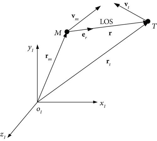
Before proceeding with the guidance law design, the following assumptions are made.
Assumption 1. Consider that the target acceleration cannot be infinite in practice. Then, it is reasonable to suppose that its magnitude is bounded, i.e., at ≤ d, where d is difficult to be precisely determined prior in practical interceptions. Thus, in the subsequent design, it is regarded as an unknown parameter to be estimated.
Assumption 2. After the handover from the midcourse to the terminal guidance, the closing velocity satisfies , where t0 is the initial time of terminal guidance and L is a positive constant.
3. Standard Tracking Profile
The typical design principle of a guidance law is that nullifying the LOSR results in the missile being in a desired collision triangle with the target, as described in Figure 2 where the LOSR is zero [7]. The lines of sight are parallel to each other at different instants. It is indicated that the relative motion between the missile and the target is in line with the LOS and a direct collision occurs in the end.
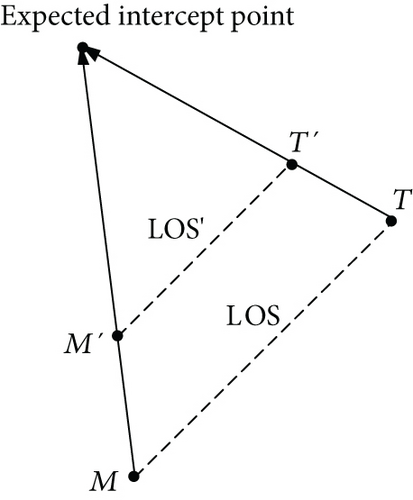
According to the principle, the guidance problem is to find an efficient commanded acceleration amθ in (5), which reduces ω to zero. In practical interceptions, however, it is almost impossible that the collision triangle is strictly satisfied because of the initial nonzero LOSR and random target maneuver. In fact, reducing the LOSR to a low level is adequate for performing a collision because of the body sizes of the missile and the target. Motivated by the concept of the standard profile tracking in the trajectory generation of entry vehicles [30], we introduce a standard profile of vθ versus r into the guidance law design, as shown in Figure 3.
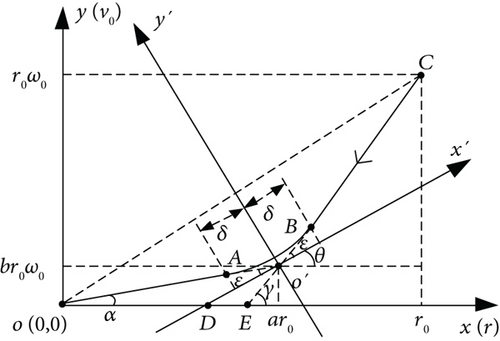
By examining the left and right derivatives of A and B, it is known that the designed profile is continuously differentiable. The change trend of the profile is formulated as the parameters a, b, and δ. Generally, δ is set as a small constant. When an accurate profile tracking is guaranteed, we can flexibly control the convergence rate of the LOSR by adjusting a and b.
4. Adaptive Guidance Law Based on Profile Tracking
4.1. Guidance Law Design
4.2. Stability Analysis
In this subsection, the stability analysis of the adaptive guidance law is performed. First, we give the following lemma required in the analysis.
Lemma 1 [21]. Suppose that there is a continuously differentiable and positive definite function V(x) defined in a neighborhood U ⊂ Rn of the origin and that where p, q > 0, and 0 < η < 1, then, x converges to zero in finite time and the settling time T satisfies the inequality
Theorem 1. For the guidance system (15) with the sliding-mode surface (16), if the guidance law is chosen as (22) with the updating law (23), then the sliding-mode variable s and the system states x1 and x2 will converge to the regions
Proof. Consider the Lyapunov function
Substituting (22) into (19) yields
By using (23) and (28), (27) is written as
Noting that
According to (32), when k1 > ζ/2ε2 and k2 > ε2/2|s|μ+1, V2 satisfies Lemma 1. Therefore, s will, in finite time, converge to the region
After that, the system states satisfy the following equation:
When |x1| ≥ ξ, (34) can be rewritten as
Choose the Lyapunov function
Then, taking the derivative of (36) with respect to time and substituting (35) into the resulting equation, we obtain
From Lemma 1, x1 will converge towards zero when
Thus, the convergence region of x1 is obtained as
Simultaneously, the convergence region of x2 is given as
The proof is complete.
4.3. Guidance Command Conversion
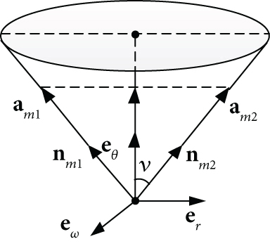
4.4. Guidance Law Realization in Practical Interceptions
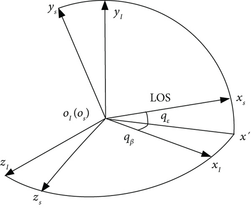
From (41) and the derivation, the involved guidance information includes the relative range r, the closing velocity , the LOSR ω, the unit vector eθ, and the missile velocity vector vm. The missile seeker (usually Doppler radar or the combination with optical sensor) can directly obtain the measurements as r, , the elevation angle qε, and the azimuth angle qβ of the LOS in the inertial reference system. The relation between the LOS angles and the inertial reference system is given in Figure 5. With filtering techniques, the LOS angle rates and can be achieved.
5. Simulations
| Guidance law | Required information | |||||||
|---|---|---|---|---|---|---|---|---|
| r | qε | qβ | tm | atθ | ||||
| PTB-AGL | ✓ | ✓ | ✓ | ✓ | ✓ | ✓ | ✓ | ✗ |
| PTB-GL | ✓ | ✓ | ✓ | ✓ | ✓ | ✓ | ✓ | ✗ |
| OE-FTC-GL | ✓ | ✓ | ✓ | ✓ | ✓ | ✓ | ✓ | ✗ |
| PPN | ✗ | ✗ | ✓ | ✓ | ✓ | ✓ | ✓ | ✗ |
| TPN-C | ✗ | ✓ | ✓ | ✓ | ✓ | ✓ | ✓ | ✗ |
| ATPN-C | ✗ | ✓ | ✓ | ✓ | ✓ | ✓ | ✓ | ✓ |
- Note: ✓ denotes “the information is required”; ✗ denotes “the information is not required.”
In addition, ΔJ is defined as the total energy consumption during the guidance process, that is, ΔJ = J(tf), where tf is the final time of guidance. The simulations below are performed on a laptop with Intel Core i5-3470 3.20 GHz CPU. The result in this section is obtained by using MATLAB 2016a.
5.1. Case 1: Pursuing a Low-Velocity Maneuverable Target
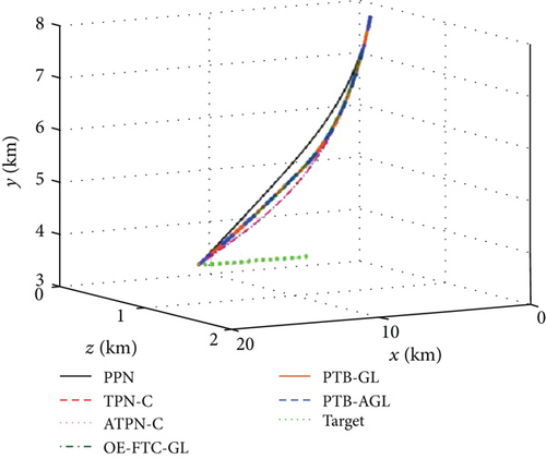
The first set of simulations is carried out for the case where a missile with a velocity advantage is pursuing a maneuverable target. The initial state of the missile and the target in oIxIyIzI is given in Table 2.
| Initial state | Missile | Target |
|---|---|---|
| Position (km) | (2, 8, 0.5) | (12, 4, 1.5) |
| Velocity (m/s) | (1101.24, -459.84, 125.76) | (500, 0, 0) |
Three different types of target motion are considered as follows: (1) constant velocity (CV): at = (0, 0, 0); (2) constant maneuvering (CM): at = (0, 3g0, 4g0), g0 = 9.80665 m/s2; and (3) sinusoidal maneuvering (SM): at = (0, 3g0, 5g0cos0.5t). The simulation step is 1 ms when r ≥ 2 km and 0.1 ms when r < 2 km. The simulation terminates when , and the miss distance is defined as the minimum value of r. The missile acceleration is limited by amax = 10g0. The seeker blind-zone distance is selected as 100 m, and the guidance command keeps unchanged when r is less than the distance. The time constant of the autopilot dynamics is set as 0.1 s. At the initial time t0, nm = (0.3948, 0.9092, -0.1324), and are adopted. The key parameter settings involved in the guidance laws are listed in Table 3, and the other parameters for modification are chosen as δ = 0.05r0, σ = 0.01, and χ = 5.
| Guidance law | Parameter |
|---|---|
| PTB-AGL | a = 0.5, b = 0.05, α1 = α2 = 2, γ = 0.8, ξ = 0.01, k1 = k2 = 2, μ = 0.1, k3 = 0.1, k4 = 0.001, ε = 0.8 |
| OE-FTC-GL | N1 = 3.0, α = 10.0, υ = 0.1, δω = 5.0 × 10⁻⁴ |
| PPN/TPN-C | N2 = N3 = 3.0 |
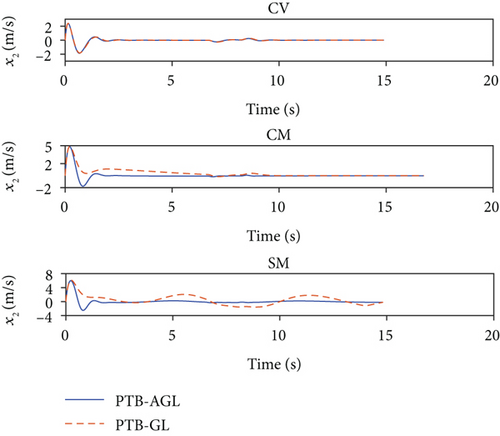
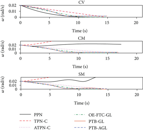
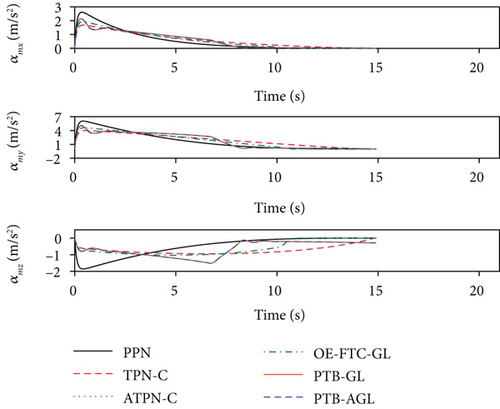
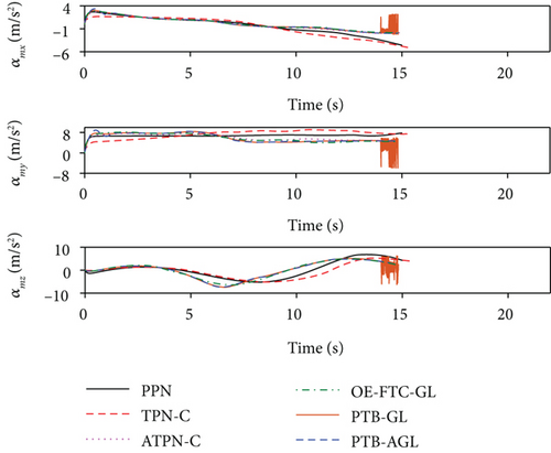
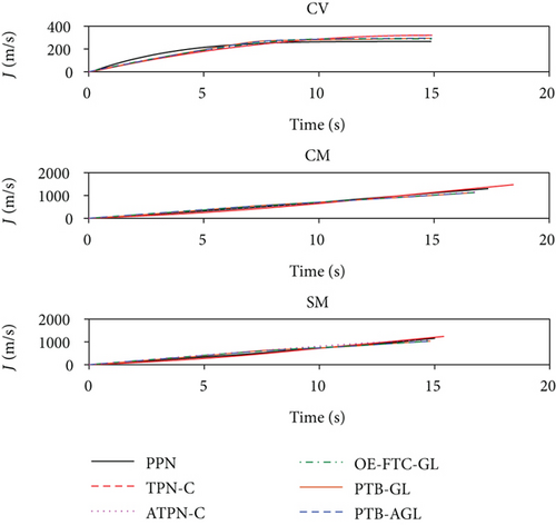
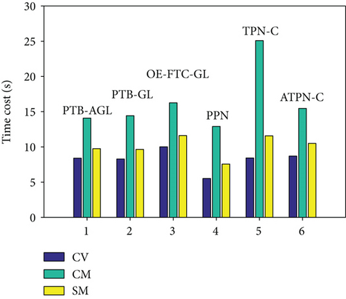
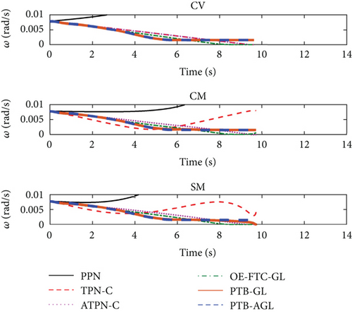
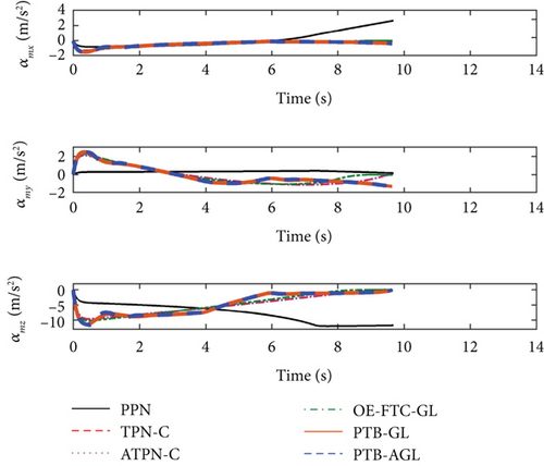
Based on the above conditions, the simulation results are presented in Figures 6(a)–6(j) and Table 4. In Figure 6(d), the profile-tracking error of PTB-AGL rapidly converges to a small neighborhood of zero in comparison to that of PTB-GL, especially when against the CM and SM targets. This indicates that the addition of the adaptive term can better reject the target maneuver disturbance in PTB-AGL. It can be seen in Figure 6(e) that all the laws are able to reduce the LOSR to a low level in terms of intercepting the CV target. In addition, the least energy is consumed in PPN from Table 4. However, when dealing with the maneuvering targets, PPN and TPN-C, compared with the other four laws, cannot suppress the LOS rotation well because the target maneuver disturbance is not addressed. Thus, as shown in Table 4, they have larger miss distance and total energy consumption. Because of the direct target maneuver compensation, ATPN-C is significantly better than TPN-C. The histories of the guidance acceleration command are plotted in Figures 6(f)–6(h). When intercepting the SM target, the command of PTB-AGL is smooth while the unexpected chattering emerges in PTB-GL and ATPN-C, which demonstrates that the designed adaptive term works well. The CPU time costs of the laws are presented in Figure 6(j) where PTB-AGL has an advantage over OE-FTC-GL. This may be because an additional observer for estimation is required in OE-FTC-GL while the target maneuver is addressed by a simply adaptive term in PTB-AGL. PPN possesses the least time cost as predicted, but the unsatisfactory miss distance when against the SM target.
| Guidance law | Miss distance (m) | Total energy consumption (m/s) | ||||
|---|---|---|---|---|---|---|
| CV | CM | SM | CV | CM | SM | |
| PTB-AGL | 0.0042 | 0.0116 | 0.0222 | 294.99 | 1148.87 | 1037.89 |
| PTB-GL | 0.0048 | 0.0158 | 0.1234 | 294.99 | 1149.48 | 1044.18 |
| OE-FTC-GL | 0.0325 | 0.0241 | 0.0175 | 289.03 | 1146.27 | 1036.69 |
| PPN | 0.0206 | 0.0276 | 4.4362 | 266.20 | 1323.66 | 1174.06 |
| TPN-C | 0.0141 | 59.9252 | 74.5088 | 321.11 | 1525.42 | 1252.22 |
| ATPN-C | 0.0141 | 0.0075 | 0.1555 | 321.11 | 1182.19 | 1061.31 |
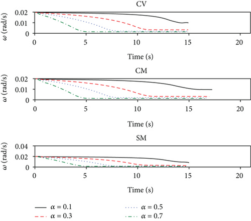
According to the above results, the guidance performance of PTB-AGL is superior to those of PTB-GL, PPN, TPN-C, and ATPN-C and, regardless of the CPU cost, comparable to that of OE-FTC-GL where the unknown target maneuver is accurately estimated and compensated due to the employment of the true guidance information. In addition, the convergence rate of the LOSR can be flexibly and quantitatively regulated by adjusting a. By contrast, OE-FTC-GL can only roughly control the convergence time of the LOSR because of the guidance scheme and the uncontrollable estimation error. The time histories of the LOSR under the different profile parameters are presented in Figure 7(a) where the convergence rate of the LOSR is flexibly controlled. Figure 7(b) shows the trends of the guidance performance versus the profile parameter at a proper interval. It can be observed that the miss distance always fluctuates within a low level and the total energy consumption varies with a. For intercepting a maneuverable target, PTB-AGL can easily give a proper convergence rate via a when the energy consumption is taken into account.
5.2. Case 2: Head-On Intercepting a High-Velocity Maneuverable Target
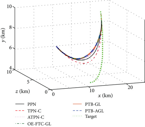
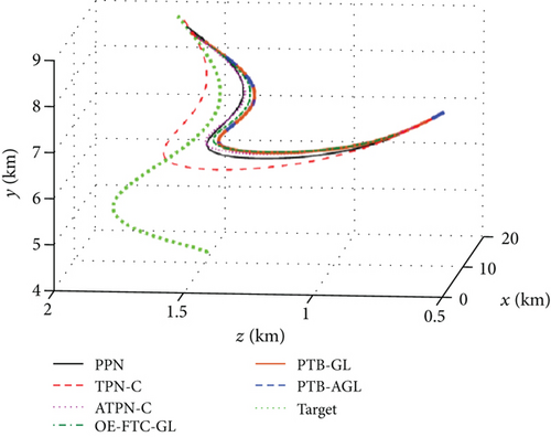
In this subsection, an engagement scenario is constructed where a missile with a velocity disadvantage is head-on intercepting a high-velocity maneuverable target. The initial state of the missile and the target in oIxIyIzI is given in Table 5.
| Initial state | Missile | Target |
|---|---|---|
| Position (km) | (45, 10, 1) | (5, 15, 1.5) |
| Velocity(m/s) | (1691.10, 497.52, 364.14) | (2400, 0, 0) |
Similarly, three different patterns of target motion are considered as follows: (1) CV: at = (0, 0, 0); (2) CM: at = (0, 2g0, 3g0); and (3) SM: at = (0, 2g0, 4g0cos0.5t). The simulation step jumps to 0.1 ms when r < 5 km. The missile acceleration is limited by amax = 12g0, and the seeker blind-zone distance is set as 300 m. At the initial time t0, nm = (−0.1369, 0.2383, −0.9615) is adopted. The parameters for the guidance laws are the same as in the previous subsection expect for δ = 0.1r0 and b = 0.1.
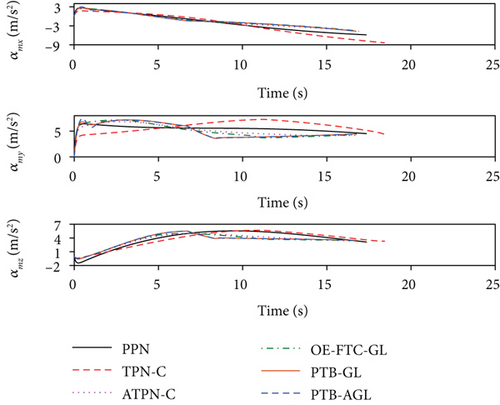
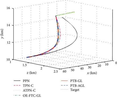
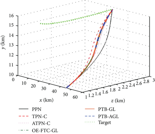
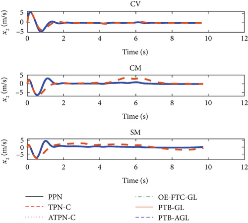
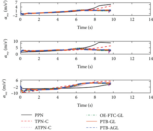
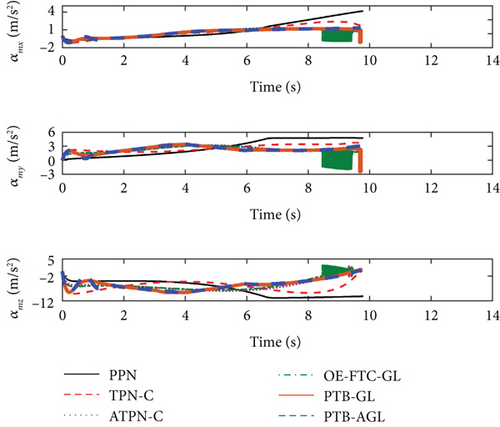
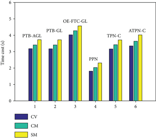
With the above conditions, the simulation results are shown in Figures 8(a)–8(j) and Table 6. From Figure 8(d), the adaptive term in PTB-AGL dramatically enhances the tracking precision of the profile, as shown in Figure 6(d). In Figure 8(e), PPN has no capacity to control the rotation of the LOS, which leads to the target missing as listed in Table 6. Likewise, the guidance acceleration of PTB-AGL is always smooth in Figures 8(f)–8(h). By contrast, ATPN-C, OE-FTC-GL, and PTB-GL yield different levels of chattering against the maneuvering targets. In terms of the energy consumption, PTB-AGL is less than TPN-C, especially when against the CM and SM targets, since the target maneuver is not considered in TPN-C. Therefore, the performance of PTB-AGL is preferable to the other four laws. Figure 8(j) gives the CPU time cost of the each law. It can be found from Figures 6(j) and 8(j) that the CPU cost is larger when intercepting the maneuvering targets, which mirrors the difficulty of dealing with maneuvering targets to some extent.

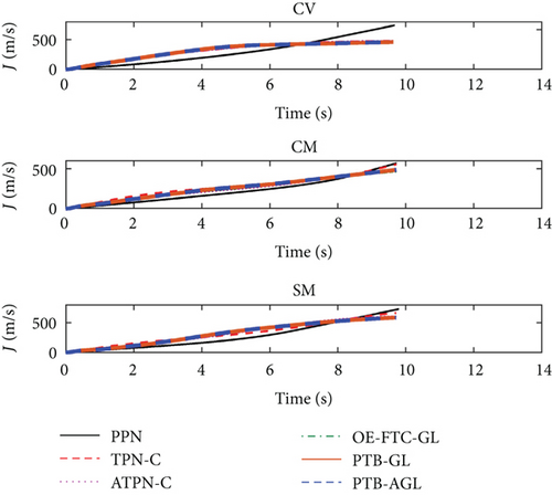
| Guidance law | Miss distance (m) | Total energy consumption (m/s) | ||||
|---|---|---|---|---|---|---|
| CV | CM | SM | CV | CM | SM | |
| PTB-AGL | 0.1682 | 0.1455 | 0.0291 | 462.41 | 492.34 | 592.21 |
| PTB-GL | 0.1615 | 0.1641 | 0.1875 | 462.43 | 492.17 | 589.86 |
| OE-FTC-GL | 0.0730 | 0.0442 | 0.1322 | 455.15 | 472.23 | 591.76 |
| PPN | 193.6181 | 91.5074 | 495.5556 | 749.64 | 579.92 | 730.59 |
| TPN-C | 0.1831 | 0.0106 | 0.0800 | 478.04 | 564.50 | 668.25 |
| ATPN-C | 0.1831 | 0.1507 | 0.1338 | 478.04 | 476.30 | 609.25 |
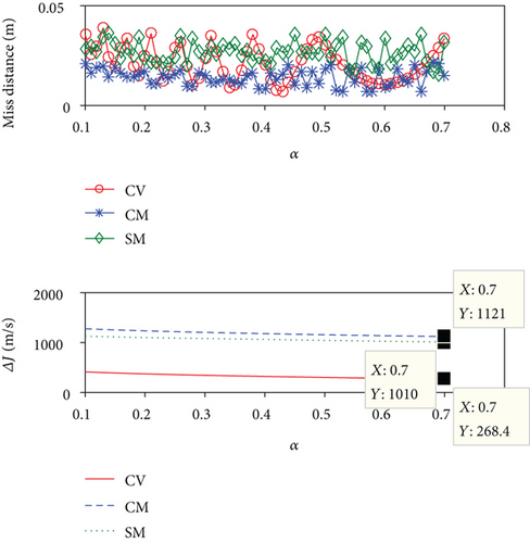
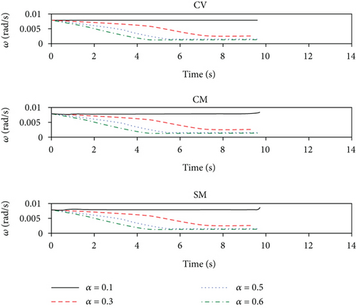
Figures 9(a)–9(b) give the time histories of the LOSR under the different profile parameters and the variations of the guidance performance versus the profile parameter, respectively. Generally, the parameter a should not be too large in view of finite tracking capability. As same as in Figure 7(a), the LOSR convergence rate of PTB-AGL can be regulated easily through adjusting a moderately in Figure 9(a). In Figure 9(b), the miss distance is kept at a low level, and the trend of the total energy consumption is different in terms of the different maneuvering types of targets. It is indicated that lowering the LOSR excessively requires more overload consumption when intercepting the CM target.

5.3. Monte Carlo Simulations with Measurement Noises
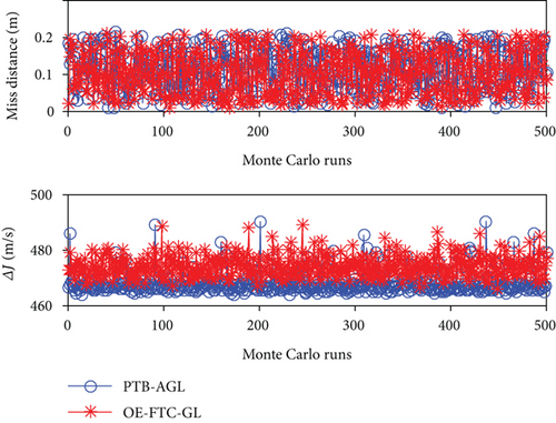
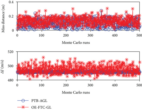
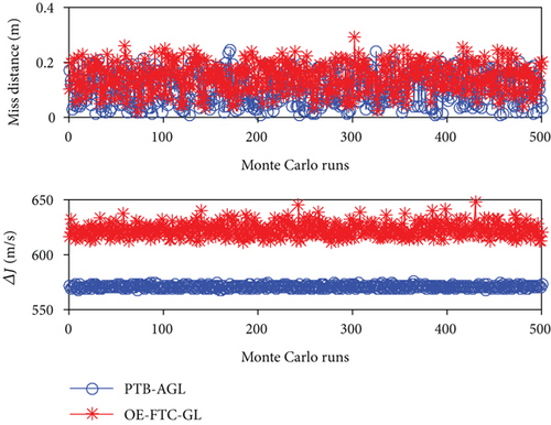
In the previous simulations, the guidance laws are implemented in a perfect scenario without measurement noise. However, in realistic scenarios, the required guidance information is inevitably contaminated with inherently noisy sensors. To examine the robustness of PTB-AGL, Monte Carlo simulations of Case 2 are conducted consisting of 500 sample runs. For the performance comparison, OE-FTC-GL is also examined. The measurement noises of the relative distance r and the closing velocity are taken as normal distributions with zero mean and triple standard deviation of 100 m and 10 m/s, respectively, and those of the LOS angle and the LOS angle rate are zero mean and triple standard deviation of 0.1 deg and 0.01 deg/s, respectively. The measurement frequency of seeker is 50 Hz. According to Figure 9(b), the value of a is modified into 0.5, 0.4, and 0.6 when intercepting the CV, CM, and SM targets, respectively, and the other simulation settings are the same as in Case 2.
The Monte Carlo simulation results of the miss distance and the total energy consumption are presented in Figure 10. The RMS values of the results are summarized in Table 7. It can be seen that the performance of PTB-AGL is satisfactory in the Monte Carlo sense, and largely better than that of OE-FTC-GL when intercepting the SM target.
| Guidance law | Miss distance (m) | Total energy consumption (m/s) | ||||
|---|---|---|---|---|---|---|
| CV | CM | SM | CV | CM | SM | |
| PTB-AGL | 0.1256 | 0.1148 | 0.1205 | 468.29 | 491.33 | 570.94 |
| OE-FTC-GL | 0.1175 | 0.1417 | 0.1548 | 474.28 | 494.95 | 622.55 |
6. Conclusions
- (1)
The combination of the nonsingular fast terminal SMC and the adaptive algorithm can reject the disturbance of target maneuver well. It is realized that the tracking error of the profile rapidly converges to a small neighborhood of zero in finite time and the convergence rate of the LOSR can be regulated flexibly and quantitatively
- (2)
The guidance-command-conversion scheme works well and can be served as a bridge from the law normal to the LOS to the one normal to missile velocity
- (3)
Reducing the LOSR as fast as possible may require more control efforts. When energy consumption is taken into account, PTB-AGL can give an appropriate convergence rate of the LOSR with respect to a maneuverable type of target
Conflicts of Interest
The authors declare that there is no conflict of interests regarding the publication of this paper.
Acknowledgments
This paper was sponsored by the Aerospace Science and Technology Foundation of China Aerospace Science and Industry Corporation Limited 2017-HT-GF-07.
Open Research
Data Availability
The data used in my manuscript is constructed by ourselves according to scenarios to be researched and completely shown in details in the manuscript. No additional data is involved.


