Joint Time and Power Allocation Algorithm in NOMA Relaying Network
Abstract
Nonorthogonal multiple access (NOMA) is one of the promising access techniques in 5G network. The application of relay in NOMA system is a hotspot in recent research. NOMA-based cooperative relay network can achieve a higher spectral efficiency and a lower outage probability. In this paper, we analyse the performance of the two-hop DF relay NOMA network scenario, where the number of cell edge users is more than the cell center user, and obtained the closed-form expression of the user′s ergodic rates and outage probabilities under the high signal-to-noise (SNR) ratio. Then, we establish an optimization model to maximize the system rates, and a joint optimal time and power allocation algorithm based on the exhaustive search and the binary algorithm is proposed. Simulation results show that the proposed scheme can outperform exiting scheme in terms of achieving a higher ergodic sum rate, a lower outage probability under the premise of fairness.
1. Introduction
As the demand for smart terminals and new mobile services continues to grow, wireless transmission rates will increase exponentially and the 4G system will be difficult to meet the communications requirements of high-speed, low-latency. Besides, the unexpected excessive energy consumption of the fourth-generation (4G) and pre-4G wireless networks causes serious carbon dioxide emissions. To achieve green wireless networks, the fifth-generation (5G) wireless networks are expected to significantly increase the network energy efficiency while guaranteeing the quality of service (QoS) for time-sensitive multimedia wireless traffics [1]. NOMA has been recognized as one of the key technologies of the fifth-generation mobile communication (5G) for higher spectral efficiency [2–4]. The key idea of NOMA is accommodating multiple users in the same frequency band but each user has a different power. Compared with the traditional OMA system, NOMA can achieve a higher spectral efficiency [5, 6]. Since cooperative relay can improve system capacity and expand network coverage [7], NOMA-based cooperative relay network has become a hotspot in wireless field research.
A preliminary study has been conducted on the resource allocation of the NOMA relay network. In [8], the strong users work as the relay, and the proposed cooperative scheme is strong user decode and transmits the weak user’s signals. The ergodic sum rate and outage probability of this cooperative NOMA scheme are analysed. In [9], a dedicated relay node is used to provide services for users equipped with multiple antennas, and the literature obtains the lower bound of the outage probability. In [10], the author studied the outage performance of the NOMA system that relay operates in amplify-and-forward (AF) strategy and derived the exact approximation of the outage probability. In [11], the author has derived the system outage probability and the ergodic sum rate of the scenario where users are directly communication with the base station (BS) and the relay. The relay operates in decode-and-forward (DF) strategy. In [12], the time and power allocation of two-hop relay using DF protocol is studied. The closed-form expression of the outage probability is derived, and the optimal time allocation for minimizing the outage probability is obtained but without considering the fairness of the system and the user communicating directly with the base station. In [13], the author analyses the scenario that the user communicates either directly with the base station or through relay with the base station and derivate the system outage probability and the expression of user ergodic rate. The theoretical and simulation results show that the ergodic sum rate of cooperative NOMA system can be significantly improved compared with noncooperation. However, the paper only analyses the case where the number of users in the cell center is equal to the number of users at the cell edge, and the time shared by the two hops is not optimized. In [14], the author analyses the performance of the scenario, where the number of cell edge users are more than the cell center users by introducing time sharing technology. However, the user is considered to communicate with the BS through the relay, and the strategy of equal time slot division and fixed power allocation factor is adopted, and the fairness of the system is not considered.
- (1)
Modelled the scenario that the number of cell center users is lower than users at the edge
- (2)
Derived the ergodic rate and outage probability of the system under the new scenario
- (3)
Proposed the joint and power allocation algorithm to maximize the system sum rate
The rest of the paper is organized as follows: section 2 gives the system model of this paper, section 3 deduces the system performance, including the derivation of the system’s ergodic rates and the outage probability, section 4 proposes an optimal allocation algorithm for time and power factor, section 5 performs simulation analysis to analyse the effect of fairness factors on the overall system rates, and section 6 summarizes the full text.
2. System Model
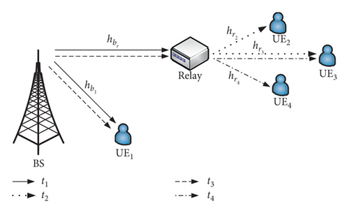
Figure 1 is the proposed system model for this paper, which contains one base station (BS), one relay (R), and four users (UE1, UE2, UE3, and UE4). We clarify that UE1 is the cell center user directly connected to the base station and has better channel conditions. UE2, UE3, and UE4 are cell edge users that need to forward information through the relay which operates in the half-duplex mode using DF strategy. The and indicate the channel coefficients from the BS to the UE1, from the BS to the relay. , , and denote the channel coefficients from the relay to each cell edge user. Channels are independent of each other and are subject to Rayleigh fading; we model these channels as , , , , and . We assume that UE2 and UE4 have similar channel conditions and the same variance, then . The channel condition of UE3 is significantly worse than other users. In the transmission process, relay forwards signals to UE2, UE3, and UE4 in NOMA strategy. We divide a transmission time slot into four subslots, and cell center users are paired with different cell edge users in different subslots for information transmission.
- (1)
During the t1 subslot, the BS transmits to the UE1 and the relay, where x1(t1), x2(t1), and x3(t1) are data symbols for UE1, UE2, and UE3 with . Ps is the transmission power of BS, and , , and are the power allocation coefficients, where and . The received signals at UE1 and relay are given by
(1)where n(•) is the additive white Gaussian noise (AWGN) at each node.
- (2)
In the t2 subslot, the relay first regenerates the superimposed signal of UE2 and UE3. Then, the relay transmits it to users. Pr is the transmission power of relay and and are the power allocation coefficients where and . The received signals at UE2 and UE3 are given by
(6)
- (3)
In the t3 subslot, the BS transmits the superimposed signals of the users 1, 3, and 4. The signal is , where , , and are the power allocation coefficients for users 1, 3, and 4, where and . The received signals at UE1 and relay are given by
(10)
- (4)
In the t4 subslot, the situation is similar to the t2 subslot, we can obtain the results as follows:
(14)where and are the power allocation factors of UE3 and UE4 in the t4 sub-time slot, respectively.
3. Performance Analysis
In this section, we analyse the system’s ergodic rates and the outage probabilities. The closed-form expression of user’s ergodic rates in high SNR is derived, and the outage probability of each user and system is obtained.
3.1. Ergodic Rates
3.1.1. Ergodic Rates of UE1
3.1.2. Ergodic Rates of UE2
3.1.3. Ergodic Rates of UE3
- (a)
If , we can obtain
(43) - (b)
If , we can obtain
(44)
3.1.4. Ergodic Rates of UE4
3.2. Outage Probability
- (1)
Outage probability of UE1
- (2)
Outage probability of UE2
- (3)
Outage probability of UE3
- (4)
Outage probability of UE4
Substituting equations (53), (56), (58), and (59) into (60), we can obtain the system outage probability.
4. Time and Power Optimization Allocation Algorithm
In this paper, we consider maximizing the system sum rate under the premise of the system fairness. Since the system sum rate in NOMA system is mainly determined by the cell center user [18, 19], it is necessary to allocate time and power resources to the cell center user as much as possible. However, due to the system fairness constrain, sufficient resources should allocate to the cell edge users to ensure users communication does not interrupt and meets the corresponding communication service quality. Therefore, the system sum rate is affected by the fairness factor F′: When the transmitting power of the base station is fixed, the more time and power resources the edge users are allocated, the higher the fairness index of the system will be, but the overall rate of the system will decrease. Therefore, the sum rates maximum is contradictory to the system fairness, and we need to compromise on the fairness and rates of the system.
From the above analysis, the system sum rate maximization is negatively correlated with the system fairness. Therefore, it is necessary to consider how to schedule time and power to maximize the system sum rate while ensuring the given fairness factor. Since the system sum rate is a piecewise function and the objective function contains multiple parameters such as time and power allocation factor, the KKT method [21] cannot be used to find the optimal value in our proposed scenario.
In this paper, we propose the joint optimal time power allocation algorithm based on exhaustive search and binary algorithm to obtain the optimal solution: firstly, the user′s power allocation factor is obtained by the following method, UE1 is the cell center user, and the allocated power is small. Since the user power allocation scheme of the t1∼t2 time slot is the same as the t3∼t4 time slot, the time slot t1∼t2 is taken as an example. According to equation (16), if , then , , , and . Let take values in a certain step in the interval [0.1, 0.5). When , searches in [0.1, (1 − k/2)). and are also obtained in this way, so that all the power allocation factor list PA_MATRIX satisfying the conditions can be obtained; secondly, according to each value set of power allocation factors in PA_MATRIX, the corresponding user outage probability can be obtained. If the user outage probability satisfies the given threshold value, the corresponding time set Li, i = 1,2,3,4 of each user when the outage probability is satisfied can be further calculated. The feasible time allocation list L can be obtained by taking the intersection of L1∼L4. Binary algorithm is then employed to find the optimal transmission time at a certain fairness factor index F′ premise; finally, the sorting algorithm is used to find the power allocation factor corresponding to the maximum system rates. This process shown in Algorithm 1.
-
Algorithm 1: Time and power optimization allocation algorithm.
- (1)
Initialization Power_list = zeros(m, n), Time_list = zeros(m, 1)
- (2)
fori = 1 : m
- (3)
Calculate user outage probability based on PA_MATRIX(i,:)
- (4)
Let then find the time set Tj meets the criteria and the intersection L
- (5)
Let tmax = L(en d) calculate system sum rates capacity(i), fairness factor fairnessIn de x
- (6)
Low = 1, High = en d, set calculation accuracy ε.
- (7)
- (8)
if Low ≠ High
- (9)
mid = ⌊High + Low⌋/2, ⌊•⌋ indicates rounding down
- (10)
tmax = L(mi d), calculate capacity(i) and fairness factor fairnessIn de x
- (11)
- (12)
- (13)
Low = mi d
- (14)
elseif fairnessIn de x < F′
- (15)
High = mi d
- (16)
elseif abs(fairnessIn de x − F′) ≤ ε
- (17)
Power_list(i,:) = PA_MATRIX(i,:), Time_list(i,:) = tmax
- (18)
break
- (19)
elseif low = = High
- (20)
break
- (21)
Time_Pa = [Time_list, Power_list], optimal time and power allocation factor matrix
- (22)
maxCapacity = maxIn de x = Optimal_Time_PA = 0, initial system maximum rate and index
- (23)
for j = 1 : length(Time_Pa)
- (24)
Calculate the system sum rates capacity(j) according to Time_Pa(j,:)
- (25)
if capacity(j) ≥ maxCapacity
- (26)
maxCapacity = capacity(j), maxIn de x = j
- (27)
Optimal_PA_Time = Time_Pa(maxIn de x,:)
When acquiring PA_MATRIX, the complexity of this algorithm to calculate , , and is O(n2), and the complexity to calculate and is O(n). Therefore, the algorithm complexity of obtaining the power allocation factor is O(n2). The calculation of time list L and system capacity can be completed in constant time, and the complexity is O(1). The complexity of the time allocation list under the feasible power set is O(log2 n).
After the feasible power and time solution set is obtained, the sorting algorithm is used to obtain the optimal time and power allocation scheme. The complexity of this step is O(n). The system complexity is T1(n) = O(n2 log2 n + n) = O(n2 log2 n). When the exhaustive search method is used, the corresponding system complexity is T2(n) = O(n3), and it can be seen that T1(n) < T2(n), so the proposed algorithm can effectively reduce the computational time complexity.
5. Numerical and Simulation Results
The simulation scenario is shown in Figure 1. It includes a base station (BS), a relay (R), and four users (UEi, i = 1,2,3,4). The relay operates in the half-duplex mode using DF strategy. UE1 is the cell center user, and denotes the channel coefficients from the BS to UE1. UE2, UE3, and UE4 are cell edge users, and , , and denote the channel coefficients from the relay to each cell edge user. We model these channels as , , , , and . The cell center user is more concerned with the ergodic rates, and the cell edge users are more concerned with the outage probability; we set different target outage probability for different users, and the simulation parameters are shown in Table 1.
| Parameter | Value | Notes |
|---|---|---|
| ρs, dB | 25∼50 | Transmits SNR of BS |
| ρr = 0.5ρs, dB | 12.5∼25 | Transmits SNR of relay |
| 1−4 | Channel variance of BS⟶UE1 | |
| 0.5−4 | Channel variance of BS⟶R | |
| , | 0.3−4 | Channel variance of BS⟶UE2,4 |
| 0.15−4 | Channel variance of BS⟶UE3 | |
| k2,3,4 | 10−3 | User outage probability target |
| RQ, bps/Hz | 0.2 | Target rates |
| F′ | 0.5 | System target fair factor index |
Figure 2 shows the theoretical and simulated rates of the user when F′ = 0.5. It can be seen from the figure that the simulation value agrees with the theoretical value. When ρs increases, the rates of each user gradually increase. UE1 rates increase rapidly at low SNR, and the growth become slower due to the constrain of system fairness index factor at high SNR. Users 2, 3, and 4 are the cell edge users, and the growth rate is slow.
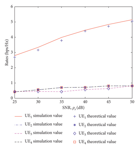
Figure 3 shows the ergodic sum rate under different fairness index factors. We have compared the system throughput optimized by Algorithm 1 with the equal time slot allocation scheme. It can be seen that the smaller the fairness index factor F′ is, the larger the system ergodic sum rate is. The larger the F′ is, the smaller the system ergodic sum rate is. When F′ = 0.4, the ergodic sum rate optimized by the proposed algorithm is greater than the equal-time transmission [11] at any SNR. When F′ = 0.5 and ρs < 45 dB, the ergodic sum rate is greater than equal-time transmission, and when ρs > 45 dB, the fairness factor of equal-time transmission is low, and the ergodic sum rate is higher than that in this paper. When F = 0.6, the value of the intersection of the ergodic sum rate by the proposed algorithm and the equal-time transmission becomes smaller.
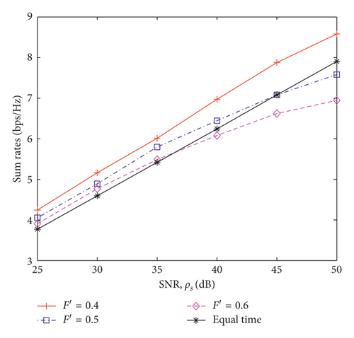
Figure 4 shows the relationship between user outage probability and ρs when F′ = 0.5. It can be seen that the user outage probability decreases as ρs increases. Since different power allocation methods are adopted for different ρs, the logarithm of the outage probability and ρs are nonlinear.
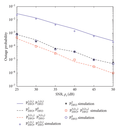
Figure 5 shows a comparison of the system outage probability of this paper and the equal-time transmission strategy. The algorithm proposed in this paper has a lower system outage probability when ρs is low. When ρs is high, the probability of two systems is close.
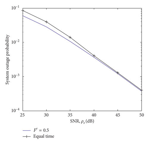
Figure 6 shows the relationship between the fairness index factor and ρs. It shows that in the case of equal-time transmission, the fairness index factor will gradually decrease as the ρs increases. However, the proposed algorithm enables the system fairness index factor maintained near the given fairness factor F′.
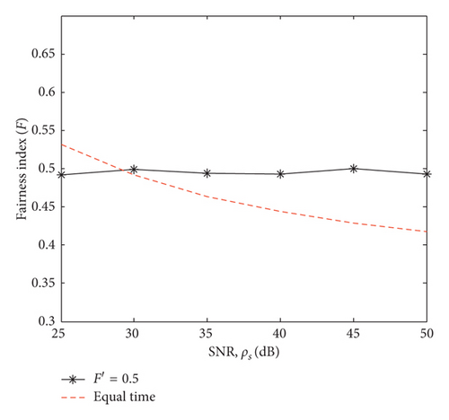
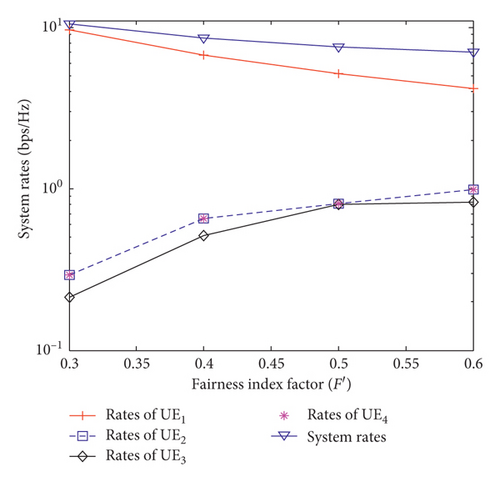
Figure 7 shows the relationship between user rates and F′ when ρs = 50 dB. It can be seen that the UE1 rates and the system sum rate are negatively correlated with F′, and users 2, 3, and 4 are positively correlated with F′. The rates of UE1 is always the largest, as F increases, and these rates of increase in users 2, 3, and 4 slow down. Because when F′ increases, the power and time resources allocated to the cell edge users rise, and the cell center user decreases accordingly. Besides, the throughput difference between users decreases. Since the cell center user has the greatest impact on system sum rate, although the cell edge users rates increase, the system sum rate still drops.
6. Conclusion
In this paper, we study the time and power optimization allocation algorithm in the NOMA relay network. Firstly, the scenario of two-hop DF relay is established. Based on this model, the expressions of user outage probability and ergodic rates are derived. Secondly, an optimization model for maximizing the system rates is constructed. Thirdly, the joint time and power factor allocation algorithm is proposed to obtain the solution of the model. The simulation result shows, under the premise of considering the fairness of the system, the system rates optimized by the proposed algorithm is significantly improved compared with the equal-time allocation.
Conflicts of Interest
The authors declare that there are no conflicts of interest regarding the publication of this paper.
Acknowledgments
This work was supported by the National Natural Science Foundation of China (61571234 and 61631020).
Open Research
Data Availability
All data included in this study are available upon request by contact with the corresponding author.


