System Performance of Cooperative NOMA with Full-Duplex Relay over Nakagami-m Fading Channels
Abstract
In this paper, we consider a dual-user nonorthogonal multiple access (NOMA) with the help of full-duplex decode-and-forward (DF) relay systems with respect to Nakagami-m fading channel environment. Especially, we derive the analytical expressions to evaluate system performance in terms of outage probability, achievable throughput, and energy efficiency. The main investigation is on considering how the fading parameters and transmitting power at the base station make crucial impacts on system performance in the various scenarios. Finally, simulations are conducted to confirm the validity of the analysis and show the system performance of NOMA under different fading parameters of Nakagami-m fading channels.
1. Introduction
With the fast growth related to cellular networks and WiFi network-aware transmission techniques, several wireless facilities to support smart devices are becoming more widespread trend. Massive connections and huge multimedia streaming are adapted to satisfy an explosive growth in the wireless data traffic transmission. As a widely recognized key technology for the fifth-generation (5G) mobile communication systems, nonorthogonal multiple access (NOMA) paradigm is proposed to support the tremendous demands on data traffic. NOMA recently investigated and the related novel architectures for NOMA have drawn great considerations in both academy and industry [1–3]. In the conventional orthogonal multiple access (OMA) schemes, in which at signal domains (i.e., frequency, time, or space), the different orthogonal channels are allocated for accommodated users. In contrast, NOMA assigns the same channel for such users. More specifically, different power levels are nominated to different data flows with assistance of the superposition coding (SC) at the transmitter. At the receiver, the successive interference cancellation (SIC) is deployed to detach separated signals. As a result, main advantages including massive connections, reduced communication latency, and increased spectral efficiency can be achieved by the deployment of NOMA [1, 2].
More recent works have considered the integration of cooperative relaying transmission with energy harvesting in systems [4–8] and with NOMA systems in [9–11]. The crucial advantage of the combined model is that users need the help of the dedicated relays cooperative in NOMA systems to further expand both transmission reliability and energy efficiency [12–20]. Specifically, users with strong channel conditions proceeded as relays to assist the users with weak channel conditions in a cooperative NOMA (C-NOMA) scheme proposed in NOMA-based cellular network [10]. Other trends are applications for wireless power transfer to NOMA as interesting investigation in [6, 8]; that is, simultaneous wireless information and power transfer (SWIPT) technique was used in relaying systems, in which trade-offs between outage performance and energy harvesting coefficients are examined. Additionally, the overlay cognitive radio (CR) networks can require C-NOMA, where a secondary transmitter [12] or a secondary receiver [13] helps as a relay and supports transmitting the primary messages, and hence, the primary network assigned the same frequency band can be able to deliver multiple access capabilities. To expand the performance, a dedicated relay can be employed in NOMA systems [14–20]. In [14, 15], the classical three-node cooperative relaying system (CRS) was applied in NOMA, where the source transfers two symbols with dissimilar power levels possessing superposition coding to a dedicated half-duplex relay so that the acquired symbols corresponding to two time slots are forwarded to the destination. In [16, 17], to increase the performance of the user with the poor channel condition, two-user NOMA systems were measured in two scenarios, including deploying a dedicated half-duplex relay [16] and deploying a dedicated full-duplex relay [17]. Additionally, a variable gain relay was presented to simplify the transmission between the source and NOMA users to serve multiusers in NOMA systems in the case of nonexistence of direct link transmissions as in [18]. System performance such as exact and asymptotic high signal-to-noise ratio (SNR) expressions were presented to illustrate the superiority of NOMA over orthogonal multiple access (OMA) with respect to applied Nakagami-m fading channels [20]. While a fixed gain relay and direct link transmissions were considered to examine performance in concerned NOMA-based relaying networks [18, 19]. With regard to wireless power transfer, a SWIPT-based decode-and-forward (DF) relay was considered in NOMA-based relaying network [21].
Recently, due to its potential to double the spectral efficiency, full-duplex (FD) wireless communication has attracted substantial attentions by permitting concurrent downlink (DL) and uplink (UL) transmission in the same frequency band [22–24]. The two-way communication links in a two-user FD scheme were inspected in terms of the rate region and the achievable sum rate [25, 26], respectively. Most of the researches on NOMA schemes rely on the Rayleigh fading channel model. Nevertheless, Rayleigh fading is considered as the special case of fading channels. Alternately, it is the most effective way to consider influences of Nakagami-m fading channels in the outage performance evaluation of NOMA with regard to the line of sight (LoS) transmission. To our best knowledge, the wide-ranging topic-related wireless analysis, i.e., Nakagami-m fading channels in relaying-aware NOMA, has not been well considered yet in the previous literature. In [18], the closed form and lower and upper bounds on the ergodic sum rate together with the outage probability have been provided in amplify-and-forward (AF) relaying over Nakagami-m fading channels, whereas the achievable rates over Rayleigh fading channels in the decode-and-forward (DF) scheme have been explored in [27]. Contrasting with the case single of antenna equipped in all nodes as recent works [18, 27], the outage performance analysis over Rayleigh fading channels deploying multiple antennas has been assigned for the source and all destinations in [28]. Furthermore, by resolving the combined power allocation and relay beamforming scheme, the maximum sum rate has been attained in the case of multiple antennas equipped in the relay, while the single antenna is equipped in source and all destinations [29]. In [30], the authors studied the performance of the cooperative relay scheme with a single relay over Nakagami-m fading channels in terms of downlink in NOMA, in which both DF and AF protocols are examined. To determine the decoding order of cell-edge users’ data, they adopt statistical channel state information (CSI) for such system and the closed form of the ergodic sum rate and outage probability are derived. In a similar trend, the authors in [19] developed new closed-form expressions of both precise and approximate outage probabilities of fixed gain AF relaying in NOMA.
- (i)
We investigate the outage performance for NOMA systems with the proposed FD relaying strategy, and it is derived in the closed form for the considering scenario. On the contrary, the performance comparisons among proposed NOMA, with FD and half-duplex (HD) relaying schemes are also provided.
- (ii)
We examine the achievable throughput based on the derived outage probability. To look insights regarding energy, we consider energy efficiency performance for the proposed system model.
- (iii)
Computer simulations are conducted to verify the accuracy of the theoretical analyses. Main results show that NOMA with the higher fading parameter and higher transmitting power of the BS outperforms the remaining cases in terms of outage performance and throughput. Such results exhibit a better behavior in NOMA with the improved channel condition, especially in the high transmitting power region.
The remaining of this paper is organized as follows. The overall system model and assumptions are introduced in Section 2. In addition, Sections 3 and 4 represent the detail analytical derivations of the outage probability for FD and HD transmission mode, respectively. In Section 5 provides simulation results, and Section 6 provides a conclusion for this research.
2. System and Signal Model
2.1. Network Topology and Channel Assumptions
2.1.1. Network Topology
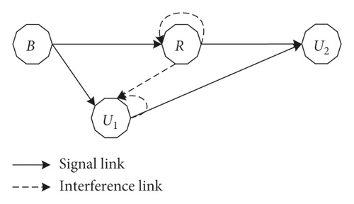
The considered FD cooperative relaying NOMA network is depicted in Figure 1, where a base station assigned with single antenna, denoted by B, transfers the information toward two single antenna equipment users, U1 and U2, by exploiting the power domain division technique, namely, NOMA. In such a model, it is assumed that existence of the B⟶U1 link can be seen due to nearer distance, while the connection of B⟶U2 link is nonexistence. Hence, B directly transmits messages to U1 and indirectly sends to U2 with help of the intermediate relay node which is denoted by ℛ. Specially, in order to enhance the spectral efficiency, ℛ is designed to operate in the full-duplex mode and thus ℛ facilitates two antennas as assumed in [9, 17]. It is worth noting that the multiple antenna relay node can further mitigate the self-interference power; however, this approach leads system to be more complex [31]. Thus, we assume the single antenna for transmitting and receiving at terminals in this work. It can refer as a typical situation of a multiantenna scheme as investigated in [9, 17].
2.1.2. Outdated Channel Model
2.1.3. Channel Statistic Distribution
Additionally, the channel coefficients are denoted as follows: the channels from B to U1 and from B to ℛ are h1 and hr, respectively. The connection between ℛ (or U1) and U2 be g2 (or g1), while the self-interference link at ℛ and interference of ℛ⟶U1 link are symbolized as fr and f1, respectively. In general, the channel gain |x|2 follows the gamma distribution with parameter mx and λx with x ∈ {h1, hr, g2, g1, fr, f1}.
Remark 1. It is noted that, although the considered system in this study is as same as in [9, 17], the channel conditions investigated in our system undergo imperfect knowledge of the Nakagami-m fading environment. Since such channel condition is more general than the Rayleigh fading environment in [9], and this research can be considered as a generalized version of previous work in [17] when considering nonideal interference cancellation hardware for both co-channel interference at U1 and self-interference at ℛ, taking imperfect CSI noise into account.
Remark 2. In this paper, the severity fading parameter, i.e., m, is strictly supposed as an integer value. Thus, the analytical expression is only true for such considerations. The general case of noninterger values of m is beyond the scope of this study.
2.2. Full-Duplex NOMA Relaying Scheme and Signal Analysis
2.2.1. Cooperative NOMA FD Relaying Scheme
2.2.2. The Near NOMA User-Aided Cooperative NOMA FD Relaying Scheme
In the sequels, the system performance in terms of outage probability will be analysed.
3. Outage Probability Consideration on Full-Duplex Relaying NOMA
3.1. Outage Probability of U1
3.1.1. Cooperative NOMA FD Relaying Scheme
Proposition 1. Putting and . The outage probability of U1 for such a considered system over the Nakagami-m fading condition is given by
Proof 1. See Appendix.
With the high SNR regime, i.e., , and the approximate expression ex ≈ 1 + x for x⟶0, we can achieve the approximation as
Starting from (A.2), we can achieve the asymptotic expression as
Finally, by applying Eq. 6.455.1 of [34] for the last integral, the asymptotic outage probability of U1 is given by
3.1.2. User-Aided Cooperative NOMA FD Relaying Scheme
Substituting (12) and (13) into (24), the U1 outage performance is given in Proposition 2.
Proposition 2. The outage probability of U1 for the user-aided relaying cooperative FD relay system under the Nakagami-m fading environment is determined as
Proof 2. The procedure is similar that in Appendix.
In case of ϑ > 0, we get the approximate expression:
3.2. Outage Probability of U2
3.2.1. Cooperative NOMA FD Relaying Scheme
Proposition 3. We denote , , , and , and the outage probability of U2 is given by
Proof 3. See in Appendix.
The approximate expression is given as
With the help of equality in Eq. 8.354.2 of [34], since ρℛ⟶∞, we can get
3.2.2. User-Aided Cooperative NOMA FD Relaying Scheme
Proposition 4. The outage probability of U2 for the suggested U1-aided FD relaying cooperative NOMA system is given by
Proof 4. The results can be obtained by similar way in proof 3.
Similar approximating procedure for U1, the approximate expression for U2 with user-aided relaying is derived.
3.3. Delay-Limited Throughput and Energy Efficiency for FD Relaying NOMA
4. A Comparison Study on Half-Duplex Relaying NOMA
For the comparison purpose, the HD NOMA relaying is represented as a benchmark. Some results for the HD cooperative NOMA system can be addressed in [16]. Unlike the FD NOMA relaying architecture, the HD ones divide a data transmission period into two slots. In the first phase, the source B transmits message to U1 and ℛ based on the superposed signal in (4); thus the SINR at U1 for retrieving U2 data and its own data are, respectively, given by and while the SINR at ℛ to detect U2 symbol can be expressed as with and .
In the second phase, we consider two scenarios of implementation as in the FD transmission mode, such as conventional and proposed user-aided relaying for the HD cooperative NOMA system. Firstly, for the conventional cooperative NOMA network, the relay ℛ regenerates and forwards signal to U2 while the source and U1 remain silent. Thus, the SNR at user U2 from ℛ in the latter time slot is given by . Secondly, in the case of user U1-aided relaying scheme, the SINR at U2 from U1 is with and . Similarly, by exploiting selection combining technique at the far user, the received SINR is given by . It is noted that the SINR of U1 and U2 for the proposed user-aided relaying HD scheme is similar to that for the conventional HD cooperative scheme except that transmitting power is replaced by the corresponding proposed power, i.e., , , and . In what follows, we will study the outage probability of considered HD networks.
4.1. Outage Probability of U1
For the proposed FD user U1-aided relaying cooperative NOMA system, the outage probability is easily obtained by replacing ρB with .
4.2. Outage Probability of U2
Proof 5. It can be achieved by using the similar analysis that in the FD mode.
5. Numerical Results
In this section, the effectiveness channel factor to the NOMA relaying system is simulated. In the simulation, the noise is normalized, i.e., N0 = 1. The final results are averaged over 106 realization runs. For fairness in comparison, we assume the total power budget to equal ρ, the transmitted power is set up for conventional cooperative NOMA scheme ρB = ρℛ≜ρ/2 and that for the user-aided relaying scheme . Unless other stated, the target rates of U1 and U2 are set R1 = 0.5 and R2 = 1, respectively. The allocated power fraction be a1 = 0.2 so that a2 = 0.8. We also set the fading severity parameter as .
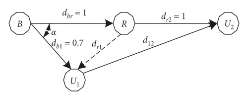
The system model is conducted as Figure 2. The distances between nodes x and y are denoted dxy with (x, y) ∈ {(b, r), (r, 2), (b, 1), (r, 1), (1,2)}. We normalize dbr = dr2 = 1 and db1 = 0.7. The angle between B⟶ℛ link and B⟶U1 link is α. Hence, the space form relay to U1 is and distance between U1 and U2 is . In order to invoke large-scale fading, the channel power mean parameters are set as the following function of distance, such as , , , and . . The power mean of self-interference links at relay and U1 after precancellation is set , where κ is the imperfect CSI level, n is the exponential loss factor, and ε represents the interference mitigation level. Unless other stated, we set α = π/4, n = 3, and ε = 0.01.
Figures 3 and 4 plot the impact of the fading parameter m on the outage performance with varying total transmitted power. It is experimentally illustrated that the fading parameters of the transmission links have a great influence on the outage performance. The outage performance with a higher m outperforms the ones with the lower m. This is because a higher m implies a stronger received SNR at destination. Furthermore, the main reason is that a larger fading parameter leads to a higher diversity order for the user, resulting in a lower outage probability [18]. As shown in Figures 3 and 4, analysis results match very well with the Monte Carlo simulation curves.
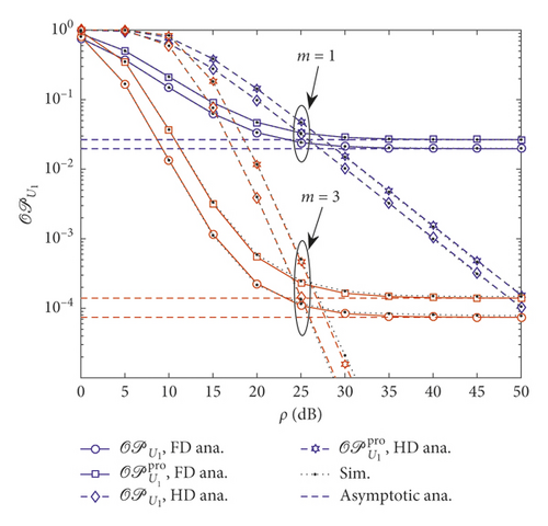
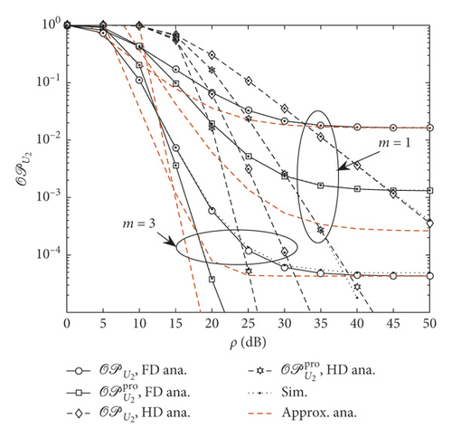
Performance gap can be seen among three cases of outage probability related to users U1 and U2. Furthermore, there exists a saturation for the outage probability in the higher transmit power region. One can also observe from Figure 4 that the fading parameters of all links (m = 5) have crucial impact on the outage performance.
Figures 5 and 6 investigate the impact of imperfect CSI level on the outage performance of the system.
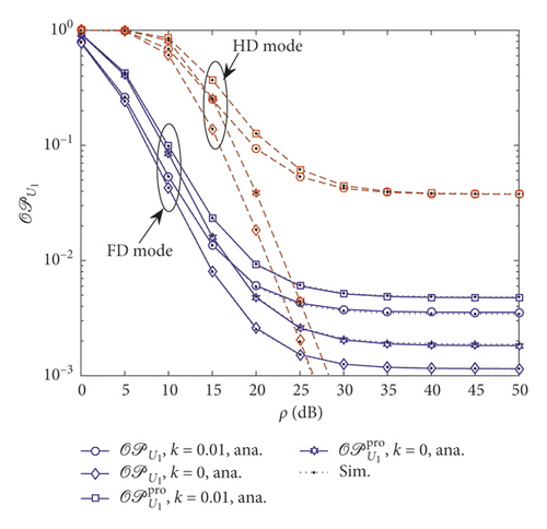
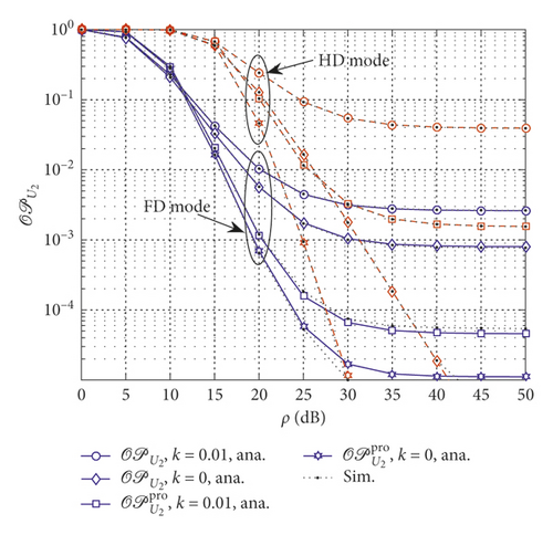
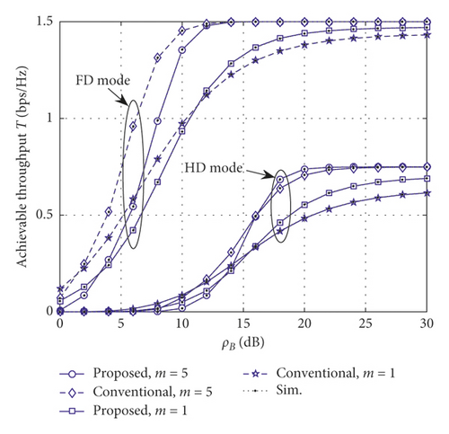
Figure 7 provides a comparison of the achievable throughput by considering two concerned modes at relay. Note that the considered system also gains benefit of the FD scheme and achieves a higher throughput as increasing the fading parameters. However, performance gap as varying fading parameters can be seen clearly in transmitting power ranging from 10 dB to 20 dB for the FD scheme and ranging from 15 dB to 25 dB for the HD scheme. It is worth noting that throughput performance of the HD scheme for the one time slot is lower than the remaining schemes. To sum up, the better channel condition leads to higher throughput can be obtained and such throughput reaches the limited value at a high level of transmitting power at B. Such observations verify the accuracy of our derived expressions.
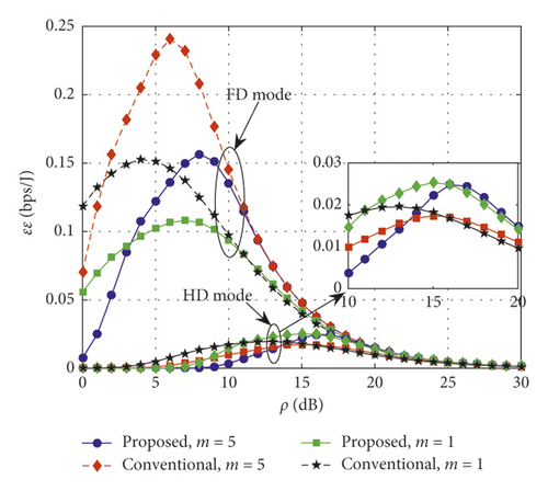
From Figure 8, we can see that the NOMA using the FD mode always outperforms the NOMA using the HD mode in terms of the optimal energy efficiency. Interestingly, optimal energy efficiency can be achieved at the FD mode and HD mode during the first time slot, but such values can only be found by using the numerical method. Moreover, the low energy efficiency can be seen at high transmitting power of B. The reason is that putting more power at B reduces energy efficiency of the considered system.
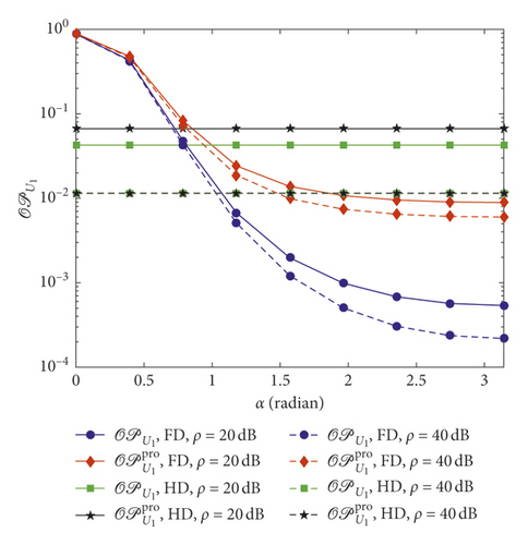
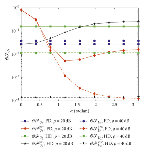
Figures 9 and 10 show the variation of outage performance of U1 and U2 under impact of angle α with κ = 0.01, m = 3, and ε = 0.1. As can be seen from Figure 9, the outage probability of FD network decreases when α increases from 0 to π. This is due to the decline of interference from relay to U1 since the distance between these nodes grow. However, performance of the HD scheme does not suffer from this variation. From Figure 10, there are some fluctuations of U2 outage. Outage performance of the proposed user-aided relaying FD scheme outperforms than that of the conventional scheme when α ≥ π/4. This can be explained that since space between relay and user U1 is large enough, it leads to the small interference between nodes and improves the proposed user-aided relying.
6. Conclusion
In this paper, the system performance of cooperative NOMA networks over imperfect Nakagami-m fading environments has been studied. We have derived the closed-form expressions of the outage probability and delay-limited throughput and energy efficiency for both conventional relaying and near user-aided relaying for the cooperative NOMA system. The numerical simulations have been conduced to verify the exactness of analytical expressions. The results show that the system performance can further be enhanced by improving either severity parameter m or exactness of the channel as imperfect CSI is raised. In addition, the simulation results also reveal that the near user-based relaying for the cooperative NOMA scheme can improve far user performance; however, it degrades that of near user.
Conflicts of Interest
The authors declare that they have no conflicts of interest.
Appendix
Case 1. In the case ϑ ≤ 0, i.e., , the outage probability is always equal to one, i.e., .
Case 2. In the case ϑ > 0, i.e., , (A.1) can be computed as
According to (2) and (3), (A.2) can be solved as
Since and are independent to each other, in (29) can be further simplified as
The item can be revealed as the same as in (A.3) and given by
In addition, the second item, i.e., , can be calculated as follows:
Finally, substituting every computed equation into main formula, Proposition 3 is derived. This is the end of the proof.
Open Research
Data Availability
No data were used to support this study.


